
Interactive Environmental Sensor Station Page
An Environmental Sensor Station (ESS) is a fixed roadway location with one or more sensors measuring atmospheric, surface (i.e., pavement and soil), and/or hydrologic (i.e., water level) conditions. These stations are typically deployed as field components of RWIS. Data collected from environmental sensors in the field are stored onsite in a Remote Processing Unit (RPU) located in a cabinet. In addition to the RPU, cabinets typically house power supply and battery back-up devices.
The Figure below is an interactive diagram, select any of the sensors for more information.
Figure. Interactive Environmental Sensor Station
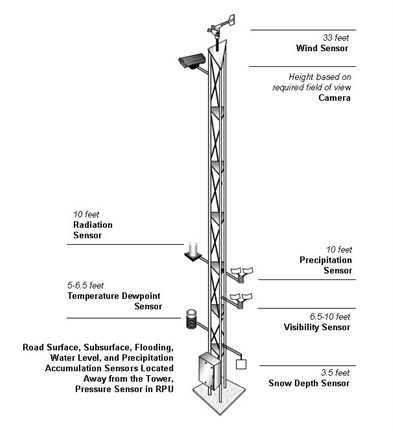
Wind Sensor
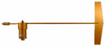 Wind Vane
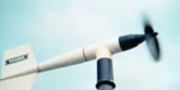 Propeller Anemometer
 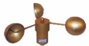 Cup Anemometer
 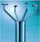 Sonic Anemometer
Wind vanes are employed to determine the direction from which wind is blowing. A conventional wind vane indicates wind direction with a tail fin mounted on a horizontal shaft that is attached to a vertical axis. The tail causes the wind vane to rotate in the horizontal plane. Wind speed is typically measured by anemometers with propellers or cups. A vane-oriented propeller anemometer uses two to four blades, which rotate about a horizontal shaft, and a vane attached to the shaft to indicate direction.
Rotating cup anemometers have three to six hemispherical cups that revolve around a vertical axis. Speed is calculated based upon the rotation rate of propeller blades or cups. Wind speed can also be determined with non-mechanical sensors, such as hot wire and sonic anemometers. Hot wire anemometers ascertain the degree of cooling of a heated metal wire, which is a function of air speed. A sonic anemometer gauges wind speeds based upon properties of wind-borne sound waves.
A wind speed and direction sensor, or anemometer, should be positioned 33 feet (10 meters) above ground level. The wind direction sensor should be set on true north, rather than magnetic north.
Camera
Visibility distance can be discerned by aiming a Closed Circuit Television (CCTV) camera at objects at known distances, such as roadside signs with flashing beacons. If cameras are used for visibility measurements, the camera should be installed as close as possible to the driver's level of view.
Radiation Sensor
Solar radiation sensors should be installed at least 10 feet (3 meters) from the surface to avoid radiation from reflective surfaces, debris contamination, and shading from obstructions. Both visible and infrared cameras should be installed where they are able to obtain a clear line-of-sight without interfering with the operation of other sensors.
Precipitation Sensor, Precipitation Accumulation Sensor
 Heated Tipping Bucket Rain Gauge with Wind Shield
  Hotplate Snow Gauge
Precipitation measurements are made with rain gauges that sense precipitation type, measure the amount and rate of rainfall (or the liquid equivalent of snow or sleet), as well as determine the start and end times of a precipitation event. Tipping bucket rain gauges and weighing rain gauges are commonly used in ESS. In tipping bucket gauges, a cylinder collects and funnels rainfall into a small bucket that holds 0.01 inches (0.30 mm) of water. In climates with frequent snowfall, the bucket is heated and equipped with a wind shield. When it is full, the bucket tips and empties the water while another bucket is lifted into position under the funnel. Every time a bucket tips an electrical contact is closed sending a signal to a recorder. Weighing rain gauges are capable of measuring all types of precipitation without heaters. Precipitation is funneled into a bucket that is weighted to assess amounts. These gauges require more maintenance than tipping bucket gauges. Float-type rain gauges use a float on the water surface to measure the amount liquid precipitation. Rain-intensity gauges or rate-of-rainfall gauges measure the instantaneous rate at which rain falls onto a surface.
A new snow gauge has been developed to provide a reliable, low maintenance method to measure snowfall rate without the use of a wind shield. The hotplate snow gauge consists of two heated plates that are used to estimate snowfall mass by measuring the power to melt and evaporate snow on the upward facing plate. The gauge compensates for wind effects by subtracting out the power on the downward facing plate. The hotplate snow gauge measures the liquid equivalent snowfall rate from 0.01 to 1.00 in/hr (0.25 to 25 mm/hr).
Optical precipitation sensors - which measure rate, type, and amount - should be installed at a height of 10 feet (3 meters) and located away from traffic, as they are susceptible to vibration. Exposure is the primary consideration for siting precipitation accumulation sensors. The tipping bucket and weighing rain gauge are the most common ESS precipitation accumulation sensors. Precipitation accumulation sensors should be placed in as open an area as possible, away from the roadway to prevent splashing, and away from areas of possible blowing or drifting snow. To increase measurement accuracy, a wind shield should be used. Snow depth sensors, which are based on ultrasonic or infrared emissions, should be installed perpendicular to the ground surface at a height of approximately 3.5 feet (1 meter) and should be mounted to avoid vibrations.
Visibility Sensor
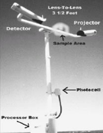 Forward-Scatter Visibility Sensor
 Visibility can be reduced by various weather phenomena including fog, heavy precipitation, drifting snow, and wind-blown dust. Visibility distance can be measured directly with sensors or remotely via Closed Circuit Television (CCTV) cameras. Objects suspended in the air - such as minute water droplets forming fog - scatter energy. Visibility sensors detect the amount of scattered light to compute visibility distances. A forward-scatter visibility sensor has a projector that emits a pulsed flash of light in a cone-shaped beam. A detector is positioned 33 to 70 degrees from the projector axis, such that the beam does not fall directly on the detector lens. Thus, the detector senses only the light scattered by fog or dust. Backward-scatter visibility sensors have aligned projectors and detectors and operate in a manner similar to forward-scatter sensors. Visibility sensors should be installed at a height of 6.5 to 10 feet (2 to 3 meters) to represent driver-level conditions. Optical sensors should be installed to prevent the sun and stray light sources from entering the receiver element.
Temperature/Dewpoint Sensor
Air temperature can be measured with liquid, gas or electrical thermometers. Electrical thermometers, which are normally used in automated sensor stations, contain metal wires that exhibit increased resistance to electrical current as the temperature rises. Platinum and copper are commonly utilized due to a nearly linear relationship between resistance of these materials and temperature. Electrical thermometers, also known as resistance thermometers and thermoelectric thermometers provide accurate readings over a wide range of temperatures.
Relative humidity - a measure of air's water vapor content - can be measured by three types of hygrometers. Dew-point, capacitor, and electrical hygrometers detect humidity by sensing changes in a substance caused by moisture. A dew-point hygrometer ascertains humidity by cooling a mirror until condensation forms. The temperature at which condensation forms can be used to calculate humidity, given the prevailing temperature and pressure. Capacitor hygrometers measure the capacitance of a material, such as polymer film, which varies as humidity changes. Electrical hygrometers accurately detect resistance to electrical current in a material, which changes with humidity. These devices typically contain a carbon-coated plastic strip that absorbs moisture from the air. As humidity rises or falls, changes in the resistance of the carbon coating can be ascertained.
An air temperature/dew point sensor should be housed in a radiation shield and mounted 5 to 6.5 feet (1.5 to 2 meters) above the ground. The sensor should be on a boom extended at least 3 feet (1 meter) from the tower in the predominant wind direction.
Snow Depth Sensor
A snow depth sensor emits an ultrasonic or infrared pulse and measures the time it takes to travel to the snow surface and return to the sensor. An internal algorithm adjusts the time, based on the air temperature, and converts it into a distance. A study by the National Weather Service found that this technology shows promise as an objective tool for measuring snow accumulation where human observations are not possible. A snow depth sensor should be installed perpendicular to the surface at a height of approximately 3.5 feet (1 meter). The sensor should have an unobstructed view of the target and should be mounted to avoid vibrations.
Road Surface Sensor
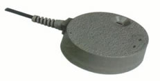 Pavement Sensor
 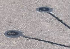 Embedded Pavement Sensors
 Surface sensors measure pavement conditions (e.g., temperature, dry, wet, ice, freeze point, chemical concentration). There are two basic types of surface sensors; active and passive. Active sensors generate and emit a signal and measure the radiation reflected by a targeted surface. Passive sensors detect energy radiating from an external source. Passive pavement temperature sensors are normally buried in the road surface. These sensors are designed with thermal properties similar to pavement so that they are heated and cooled at the same rate.
Pavement condition can be monitored with sensors embedded in road surfaces, friction measuring devices, cameras, and microphones. As shown in the figure, embedded sensors typically distinguish between two or three pavement states (e.g., dry or wet). The surface of an active pavement condition sensor is cooled below ambient air temperature. If pavement moisture is present, dew or frost will form on the cooled surface. This type of sensor can also be used to assess the effectiveness of road treatment chemicals and determine the temperature at which pavement moisture will freeze. Another type of pavement condition sensor emits microwaves from an overhead transmitter. If moisture is present on the pavement, microwaves reflect off of the water surface and the road surface. A receiver detects the pattern created by the reflections to compute the thickness and salinity of a film of water. Pavement sensors can be installed where pavement conditions are representative of general road conditions or where specific road weather problems (e.g., black ice, flooding) are likely to occur.
Subsurface Sensor
Subsurface conditions (e.g., soil temperature, soil moisture, freeze/thaw cycles) may be detected with a soil thermometer or geothermometer, which measures values at various depths. These conditions characterize the transfer of heat between the soil and the pavement. Subsurface temperature and moisture sensors should be installed at a depth of 12 or 18 inches (30.5 or 45.5 centimeters). The installation location should be representative of sub-grades in the area to include the presence or absence of water, similar soil types, and pockets of foreign materials.
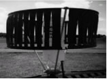
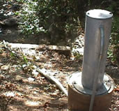 Stilling Well
 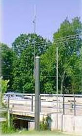 Standpipe on Bridge
Water Level Sensor
Various hydrologic sensors detect water levels in streams and rivers, and tide levels to assess flood and storm surge hazards. Ultrasonic water level sensors make use of acoustics or sound waves to measure the distance from a transducer to the water surface. Stilling wells contain float sensors to measure water levels. The float is typically enclosed in a pipe or cylinder, which protects the sensor and allows the free movement of water.
Tide gauges may be used to measure storm surge caused by a tropical storm. These gauges operate in a manner similar to stilling wells to measure the height of tide. Standpipe masts are vertical pipes ranging from 3 to 12 inches (7.6 to 30.4 centimeters) in diameter and up to 10 feet (3 meters) tall. Wind, air temperature, or other sensors should be mounted high enough on masts to eliminate the environmental effect caused by the standpipe. For water-level sensors, standpipes should be located adjacent to the low point of the flood-prone road segment in a portion of a stream or river with low turbulence (i.e., steady flowing). If installed on or adjacent to a bridge, the sensors should be sited on the downstream side to minimize damage from floating debris.
Pressure Sensor
Mercury and aneroid barometers are employed to detect atmospheric pressure or the pressure due to the force of gravity on air molecules in a column of air. Because they are more accurate than mercury barometers, aneroid barometers are typically used in meteorological applications. An aneroid barometer contains an aneroid cell - a sealed, flexible metal box or pair of thin circular disks - that expands or contracts as atmospheric pressure changes.
