| |
Microsimulation can provide a wealth of information; however, it can also be a very time-consuming and resource-intensive effort. It is critical that the manager effectively coordinate the microsimulation effort to ensure a cost-effective outcome to the study. The primary component of an effective management plan is the study scope, which defines the objectives, breadth, approach, tools, resources, and time schedule for the study. This chapter presents the key components of an overall management plan for achieving a cost-effective microsimulation analysis.
Before embarking on any major analytical effort, it is wise to assess exactly what it is the analyst, manager, and decision-makers hope to accomplish. One should identify the study objectives, the breadth of the study, and the appropriate tools and analytical approach to accomplish those objectives.
Study objectives should answer the following questions:
Try to avoid broad, all-encompassing study objectives. They are difficult to achieve with the limited resources normally available and they do not help focus the analysis on the top-priority needs. A great deal of study resources can be saved if the manager and the analyst can identify upfront what WILL NOT be achieved by the analysis. The objectives for the analysis should be realistic, recognizing the resources and time that may be available for their achievement.
Once the study objectives have been identified, the next step is to identify the scope or breadth of the analysis -- the geographic and temporal boundaries. Several questions related to the required breadth of the analysis should be answered at this time:
Development of a logical terminus of an improvement project versus a model has been debated since the early days of microsimulation; in the end, it is a matter of balancing study objectives and study resources. Therefore, the modeler needs to understand the operation of the improvement project to develop logical termini.
The study termini will be dependent on the "zone of influence," and the project manager will probably make that determination in consultation with the project stakeholders. Once that has been completed, the modeler then needs to look at the operation of the proposed facility. When determining the zone of influence, the modeler needs to understand the operational characteristics of the facility in the proposed project. This could be one intersection beyond the project terminus at one end of the project or a major generator 3.2 kilometers (km) (2 miles (mi)) away from the other end of the project. Therefore, there is no geographical guidance that can be given. However, some general guidelines can be summarized as follows:
Interstate Projects: The model network should extend up to 2.4 km (1.5 mi) from both termini of the improvement being evaluated and up to 1.6 km (1 mi) on either side of the interstate route. This will allow sufficient time and distance for the model to better develop the traffic-stream characteristics reflected in the real world.
Arterial Projects: The model network should extend at least one intersection beyond those within the boundaries of the improvement and should consider the potential impact on arterial coordination as warranted. This will capture influences such as the upstream metering of traffic and the downstream queuing of traffic.
The model study area should include areas that might be impacted by the proposed improvement strategies. For example, if an analysis is to be conducted of incident management strategies, the model study area should include the area impacted by the diverted traffic. All potential problem areas should be included in the model network. For example, if queues are identified in the network boundary areas, the analyst might need to extend the network further upstream.
A study scope that has a tight geographic focus, little tolerance for error, and little difference in the performance of the alternatives will tend to point to microsimulation as the most cost-effective approach.2 A scope with a moderately greater geographic focus and with a timeframe 20 years in the future will tend to require a blended travel demand model and microsimulation approach. A scope that covers large geographic areas and long timeframes in the future will tend to rule out microsimulation and will instead require a combination of travel demand models and HCM analytical techniques.
Traffic Analysis Toolbox, Volume II: Decision Support Methodology for Selecting Traffic Analysis Tools 3 (a separate document) provides detailed guidance on the selection of an appropriate analytical approach. This section provides a brief summary of the key points.
Microsimulation takes more effort than macroscopic simulation, and macroscopic simulation takes more effort than HCM-type analyses. The analyst should employ only the level of effort required by the problem being studied.
The following are several situations where microsimulation is the best technical approach for performing a traffic analysis:
For example, most of the HCM procedures assume that the operation of one intersection or road segment is not adversely affected by conditions on the adjacent roadway.4 Long queues from one location interfering with another location would violate this assumption. Microsimulation would be the superior analytical tool for this situation.
Because they are sensitive to different vehicle performance characteristics and differing driver behavior characteristics, microsimulation models are useful for testing intelligent transportation system (ITS) strategies designed to modify these characteristics. Traveler information systems, automated vehicle guidance, triple- or quadruple-trailer options, new weight limits, new propulsion technologies, etc., are all excellent candidates for testing with microsimulation models. The HCM procedures, for example, are not designed to be sensitive to new technology options, while microsimulation allows prediction of what the effect of new technology might be on capacity before the new technology is actually in place.
The selection of the appropriate analytical tool is a key part of the study scope and is tied into the selection of the analytical approach. Some of the key criteria for software selection are technical capabilities, input/output/interfaces, user training/support, and ongoing software enhancements.5
Generally, it is a good idea to separate the selection of the appropriate analytical tool from the actual implementation of the tool. This can be accomplished through a selection process that is independent from any project-level analytical activities. Traffic Analysis Toolbox, Volume II: Decision Support Methodology for Selecting Traffic Analysis Tools, identifies several criteria that should be considered in the selection of an appropriate traffic analysis tool and helps identify the circumstances when a particular type of tool should be used. A methodology also is presented to guide the users in the selection of the appropriate tool category. This report includes worksheets that transportation professionals can use to select the appropriate tool category and assistance in identifying the most appropriate tool within the selected category. An automated tool that implements this methodology can be found at the FHWA Traffic Analysis Tools Web site at: https://ops.fhwa.dot.gov/Travel/Traffic_Analysis_Tools/traffic_analysis_toolbox.htm
The technical capabilities of the software are related to its ability to accurately forecast the traffic performance of the alternatives being considered in the analysis. The manager must decide if the software is capable of handling the size of problems being evaluated in the study. Are the technical analytical procedures that are incorporated into the software sensitive to the variables of concern in the study? The following is a general list of technical capabilities to be considered in the selection of software:
Input, output, and the ability of the software to interface with other software that will be used in the study (such as traffic forecasting models) are other key considerations. The manager should review the ability of the software to produce reports on the MOEs needed for the study. The ability to customize output reports can also be very useful to the analyst.
It is essential that the manager or analyst understand the definitions of the MOEs as defined by the software. This is because a given MOE may be calculated or defined differently by the software in comparison to how it is defined or calculated by the HCM.
User training and support requirements are another key consideration. What kind of training and support is available? Are there other users in the area that can provide informal advice?
Finally, the commitment of the software developer to ongoing enhancements ensures that the agency's investment in staff training and model development for a particular software tool will continue to pay off over the long term. Unsupported software can become unusable if improvements are made to operating systems and hardware.
The resource requirements for the development, calibration, and application of microsimulation models will vary according to the complexity of the project, its geographic scope, temporal scope, number of alternatives, and the availability and quality of the data.6
In terms of training, the person responsible for the initial round of coding can be a beginner or on an intermediate level in terms of knowledge of the software. They should have supervision from an individual with more experience with the software. Error checking and calibration are best done by a person with advanced knowledge of microsimulation software and the underlying algorithms. Model documentation and public presentations can be done by a person with an intermediate level of knowledge of microsimulation software.
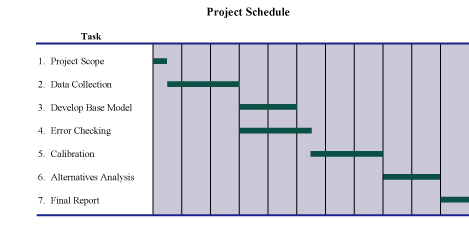
A prototype time schedule for the various model development, calibration, and application tasks is presented in Figure 2, which shows the sequential nature of the tasks and their relative durations. Data collection, coding, error checking, and calibration are the critical tasks for completing a calibrated model. The alternatives analysis cannot be started until the calibrated model has been reviewed and accepted.
Much of the management of a microsimulation study is the same as managing any other highway design project: establish clear objectives, define a solid scope of work and schedule, monitor milestones, and review deliverables. The key milestones and deliverables for a microsimulation study are shown in Table 1:
Milestone |
Deliverable |
Contents |
|---|---|---|
1. Study scope |
1. Study scope and schedule |
Study objectives, geographic and temporal scope, alternatives, data collection plan, coding error-checking procedures, calibration plan and targets |
2. Data collection |
5. Data collection results report |
Data collection procedures, quality assurance, summary of results |
3. Model development |
6. 50% coded model |
Software input files |
4. Error checking |
7. 100% coded model |
Software input files |
5. Calibration |
8. Calibration test results report |
Calibration procedures, adjusted parameters and rationale, achievement of calibration targets |
6. Alternatives analysis |
9. Alternatives analysis report |
Description of alternatives, analytical procedures, results |
7. Final report |
10. Final report 11. Technical documentation |
Summary tables and graphics highlighting key results Compilation of prior reports documenting model development and calibration, software input files |
Two problems are often encountered when managing microsimulation models developed by others:
The study manager may choose to bring more expertise to the review of the model by forming a technical advisory panel. Furthermore, use of a panel may support a project of regional importance and detail, or address stakeholder interests regarding the acceptance of new technology. The panel may be drawn from experts at other public agencies, consultants, or from a nearby university. The experts should have had prior experience developing simulation models with the specific software being used for the particular model.
The manager (and the technical advisory panel) must have access to the input files and the software for the microsimulation model. There are several hundred parameters involved in the development and calibration of a simulation model. Consequently, it is impossible to assess the technical validity of a model based solely on its printed output and visual animation of the results. The manager must have access to the model input files so that he or she can assess the veracity of the model by reviewing the parameter values that go into the model and looking at its output.
Finally, good documentation of the model calibration process and the rationale for parameter adjustments is required so that the technical validity of the calibrated model can be assessed. A standardized format for the calibration report can expedite the review process.
The example problem is a study of the impact of freeway ramp metering on freeway and surface-street operations. Ramp metering will be operational during the afternoon peak period on the eastbound on-ramps at two interchanges.7
Study Objectives: To quantify the traffic operation benefits and the impact of the proposed afternoon peak-period ramp metering project on both the freeway and nearby surface streets. The information will be provided to technical people at both the State department of transportation (DOT) and the city public works department.
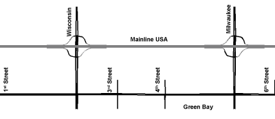
Study Breadth (Geographic): The ramp metering project is expected to impact freeway and surface-street operations several miles upstream and downstream of the two metered on-ramps. However, the most significant impact is expected in the immediate vicinity of the meters (the two interchanges, the closest parallel arterial streets, and the cross-connector streets between the interchanges and the parallel arterial). If the negative impact of the ramp meters is acceptable in the immediate vicinity of the project, then the impact farther away should be of a lower magnitude and, therefore, also acceptable.8
There is no parallel arterial street north of the freeway, so only the parallel arterial on the south side needs to be studied. Figure 3 illustrates the selected study area. There are six signalized intersections along the study section of the Green Bay Avenue parallel arterial. The signals are operating on a common 90-second (s) cycle length. The signals at the ramp junctions on Wisconsin and Milwaukee Avenues also operate on a 90-s cycle length.
The freeway and the adjacent arterial are currently not congested during the afternoon peak period and, consequently, the study area only needs to be enlarged to encompass projected future congestion. The freeway and the arterial are modeled 1.6 km (1 mi) east and west of the two interchanges to include possible future congestion under the "no meter" and "meter" alternatives.
Study Breadth (Temporal): Since there is no existing congestion on the freeway and surface streets, and the ramp metering will occur only in the afternoon peak hour, the afternoon peak hour is selected as the temporal boundaries for the analysis.9
Analytical Approach: There are concerns that: (1) freeway traffic may be diverted to city streets causing unacceptable congestion, and (2) traffic at metered on-ramps may backup and adversely impact surface-street operations. A regional travel demand model would probably not be adequate to estimate traffic diversion caused by a regional ramp metering system because it could not model site- and time-specific traffic queues accurately and would not be able to predict the impact of the meters on surface-street operations. HCM methods could estimate the capacity impact of ramp metering; however, because these methods are not well adapted to estimating the impact of downstream congestion on upstream traffic operations, they are not sufficient by themselves for the analysis of the impact of ramp meters on surface-street operations. Microsimulation would probably assist the analyst in predicting traffic diversions between the freeway and surface streets, and would be the appropriate analytical tool for this problem.
Analytical Tool: The analyst selects a microsimulation tool that either incorporates a procedure for the rerouting of freeway traffic in response to ramp metering, or the analyst supplements the microsimulation tool with a separate travel demand model analysis to predict the rerouting of traffic.10
Resource Requirements and Schedule: The resource requirements and schedule are estimated at this time to ensure that the project can be completed with the selected approach to the satisfaction of the decision-makers. The details of the resources and scheduling are not discussed here because they are specific to the resources available to the analyst and the time available for completion.
Table of Contents | List of Tables | List of Figures | Top of Section | Previous Section | Next Section | HOME