| Related: |
|
OBJECTIVES |
· Integrate and verify the system in accordance with the high-level design, requirements, and verification plans and procedures. · Confirm that all interfaces have been correctly implemented · Confirm that all requirements and constraints have been satisfied. |
|---|---|
|
Description |
The software and hardware components are individually verified and then integrated to produce higher level assemblies or subsystems. These higher-level assemblies are also individually verified before being integrated with others to produce yet larger assemblies, until the complete system has been integrated and verified. |
|
Context |
|
|
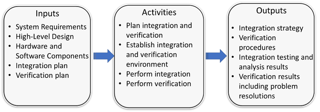
INPUT Sources of Information |
· System Requirements · High-Level Design · Hardware and Software Components · Integration plan · Verification plan |
|
PROCESS Key Activities |
· Plan integration and verification · Perform integration · Perform verification |
|
OUTPUT Process Results |
· Integration strategy · Verification procedures · Integration testing and analysis results · Verification results including problem resolutions |
In this step, we assemble the system components into a working system and verify that the system fulfills all of its requirements. Assembling a puzzle is a nice simple analogy for this step, but the challenge in an ITS project “puzzle” is that you may find that all of the pieces aren’t available at the same time, some of the pieces will not fit together particularly well at first, and there will be pressure to change some of the pieces after you have already assembled them. The systems engineering approach provides a systematic process for integration and verification that addresses the challenges and complexity of assembling an ITS system.
Integration and verification is an iterative process in which the software and hardware components that make up the system are progressively combined and verified against the requirements as shown in Figure 20. This process continues until the entire system is integrated and verified against all of its requirements. This is the opposite of the decomposition that was performed during the requirements and design steps, which is reflected in the symmetry between the left and right sides of the Vee. Components that are identified and defined on the left side of the Vee are integrated and verified on the right.
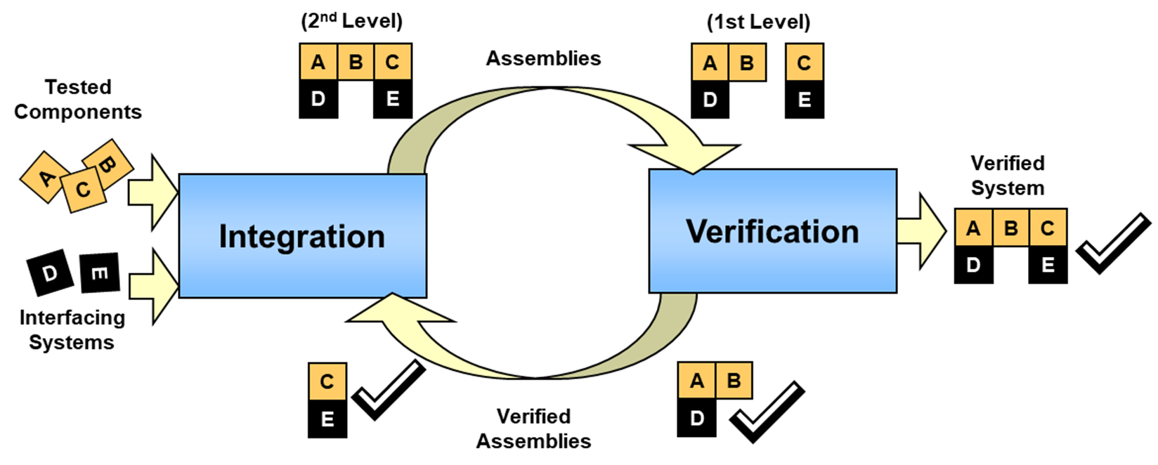
Figure 20: Iterative Integration and Verification
(Source: FHWA)
 In
systems engineering, we draw a distinction between “verification” and
“validation”. “Verification” confirms that a product meets its specified
requirements. “Validation” confirms that the product fulfills its intended use.
In other words, verification ensures that you “built the product right” while
validation ensures that you “built the right product”. This is an important
distinction because there are lots of examples of well-engineered products that
met all of their requirements, but ultimately failed to serve their intended
purpose. For example, a Bus Rapid Transit system might implement a signal
priority capability that satisfies all of its requirements. This system might
not serve its intended purpose if the traffic network is chronically congested and
the buses are never actually granted priority by the signal control system when
they need it most. Verification is discussed in this section. System validation
is described in Section 3.3.11.
In
systems engineering, we draw a distinction between “verification” and
“validation”. “Verification” confirms that a product meets its specified
requirements. “Validation” confirms that the product fulfills its intended use.
In other words, verification ensures that you “built the product right” while
validation ensures that you “built the right product”. This is an important
distinction because there are lots of examples of well-engineered products that
met all of their requirements, but ultimately failed to serve their intended
purpose. For example, a Bus Rapid Transit system might implement a signal
priority capability that satisfies all of its requirements. This system might
not serve its intended purpose if the traffic network is chronically congested and
the buses are never actually granted priority by the signal control system when
they need it most. Verification is discussed in this section. System validation
is described in Section 3.3.11.
System does not pass verification testing: The risk in this step, which is primarily technical, is that the system(s) developed for the project doesn’t function/perform as required in the expected environment.
Integrating and verifying the system is a key systems engineering activity that includes basic planning, preparation, and execution activities as described in the following paragraphs:
Plan integration and verification
Integration and verification planning actually began on the left side of the Vee. A technique for verifying every requirement was identified as the requirements were specified and a general plan for verifying all of the requirements was documented. As the overall structure of the system was defined as part of high-level design, the general strategy for integrating the system components was developed. Detail is added to these general plans based on the actual system implementation and the order in which project components and other required resources will be available is defined.
The integration strategy defines the order in which the project components are integrated with each other and with other systems that the project must interface to. Each integration step includes integration tests that verify the functionality of the integrated assembly with particular focus on the interfaces. For less complex projects, the integration strategy can be an informal plan. For complex projects, there will have to be careful planning so that the system is integrated in efficient, useful increments consistent with the master schedule.
The verification plan is expanded into verification procedures that define the step-by-step process that will be used to verify each component, subsystem, and system against its requirements. For efficiency, test cases are identified that each can be used to verify multiple requirements. Each test case includes a series of steps that will be performed, the expected outputs, and the requirements that will be verified by each step in the test case.
 The systems
engineering analysis requirements identified in FHWA 23 CFR 940.11 and FTA’s
National ITS Architecture Policy Section 6 require identification of testing
procedures, which are synonymous with the verification procedures that are
described here.
The systems
engineering analysis requirements identified in FHWA 23 CFR 940.11 and FTA’s
National ITS Architecture Policy Section 6 require identification of testing
procedures, which are synonymous with the verification procedures that are
described here.
· Establish integration and verification environment – The tools that will be used to support integration and verification are defined, procured, and/or developed. For complex systems, this could include simulators that are used to simulate operational interfaces, test equipment that is used to inject failures and monitor system responses, etc. The verification environment effectively simulates the operational environment as faithfully as possible and allows portions of the system to be tested before all interfacing components are completed.
 If test and
simulation tools are used to support system verification, then these tools
should be verified with the same care as the end product. Verifying a system
using a simulator that has not been verified could result in invalid
verification results or compensating errors where a defect in the end product
is masked by a defect in the verification tool.
If test and
simulation tools are used to support system verification, then these tools
should be verified with the same care as the end product. Verifying a system
using a simulator that has not been verified could result in invalid
verification results or compensating errors where a defect in the end product
is masked by a defect in the verification tool.
Perform integration
The system is progressively integrated based on the high-level design and the integration strategy. The system components are integrated with each other and with other interfacing systems. Integration tests are used to verify that the components and higher-level assemblies work together properly and do not interfere with one another. Integration tests are used to exercise the interfaces and verify the interface documentation in detail. The process confirms that all interfaces are implemented per the documentation. Proposed changes to the baseline high-level design, including any required changes to the interface documentation, are identified.
Perform verification
Every requirement is verified using the test cases defined in the verification procedures. System requirements and the related subsystem and component-level requirements may be verified several times as verification progresses bottoms-up from component verification to subsystem verification to system-level verification. For example, a requirement that the system “shall blank a selected dynamic message sign on user command” might be verified at several different levels. The capability of the sign to blank itself would be verified at the Dynamic Message Sign (DMS) component level. The capability of the user interface to accept and relay a “blank sign command” might be tested at the subsystem level, and finally, an end-to-end system test would be used to verify that the sign actually blanks on user command.
There are four basic techniques that are used to verify each requirement:
 Test:
Direct measurement of system operation. Defined inputs are provided and outputs
are measured to verify requirements have been met. Typically, a “test” includes
some level of instrumentation Tests are more prevalent in early verification
tests where component-level capabilities are being exercised and verified.
Test:
Direct measurement of system operation. Defined inputs are provided and outputs
are measured to verify requirements have been met. Typically, a “test” includes
some level of instrumentation Tests are more prevalent in early verification
tests where component-level capabilities are being exercised and verified.
Demonstration: Witness system operation in the expected or simulated environment without need for measurement data. For example, a requirement that an alarm is issued under certain conditions could be verified through demonstration. Demonstrations are more prevalent in system level verification where the complete system is available to demonstrate end-to-end operational capabilities.
Inspection: Direct observation of requirements that are easily observed such as construction features, workmanship, dimensions and other physical characteristics, software language used, etc.
Analysis: Verification using logical, mathematical, or graphical techniques. Analysis is frequently used where verification by test would not be feasible or would be prohibitively expensive. For example, a requirement that a web site support up to 1,000 simultaneous users would normally be verified through analysis.
As each verification test case is performed, all actions and system responses are recorded. All unexpected responses are documented and analyzed to determine the reason for the unexpected response and define a plan of action that might involve repeating the test, revising the test case, fixing the system, or even changing the requirement. Any changes to the test cases, the requirements, or the system are managed through the configuration management process.
 It is important to keep strict configuration
control over the system components and documentation as you proceed through
verification. The configuration of each component and the test case version
should be verified and duly noted as part of the verification results. It is
human nature to want to quickly find and fix a problem “on the spot”, but it is
very easy to lose configuration control when you jump in to make a quick fix.
In addition, such quick fixes can invalidate preceding verification tests since
a change may have unexpected effects on another part of the system.
It is important to keep strict configuration
control over the system components and documentation as you proceed through
verification. The configuration of each component and the test case version
should be verified and duly noted as part of the verification results. It is
human nature to want to quickly find and fix a problem “on the spot”, but it is
very easy to lose configuration control when you jump in to make a quick fix.
In addition, such quick fixes can invalidate preceding verification tests since
a change may have unexpected effects on another part of the system.
 Resist the temptation to scale back verification
activities due to budget or schedule constraints. This would be false economy
because defects that slip through will be even more expensive to fix later in
the system lifecycle. As previously noted, it is most efficient to identify
defects early in the verification process. This approach also minimizes the
number of issues that will be identified during system verification, which is
the most formal and most scrutinized verification step. Issues that occur
during a formal system verification that is witnessed by stakeholders can
undermine confidence in the system. Be sure to run the system verification test
cases beforehand to the extent possible to reduce the risk of unexpected issues
during a formal system verification.
Resist the temptation to scale back verification
activities due to budget or schedule constraints. This would be false economy
because defects that slip through will be even more expensive to fix later in
the system lifecycle. As previously noted, it is most efficient to identify
defects early in the verification process. This approach also minimizes the
number of issues that will be identified during system verification, which is
the most formal and most scrutinized verification step. Issues that occur
during a formal system verification that is witnessed by stakeholders can
undermine confidence in the system. Be sure to run the system verification test
cases beforehand to the extent possible to reduce the risk of unexpected issues
during a formal system verification.
Lessons Learned: As you approach the end of the effort, it is a good idea to consider documenting Lessons Learned on the project. It is always a good practice to maintain a “Lessons Learned” memo or report which may be used by future systems engineering staff that are developing new but similar systems. The lessons learned document captures for each stage of the SE process, which decisions or approaches were unexpectedly valuable (or useless). These lessons learned can be invaluable to future system owners and the systems engineers that work to develop, operate, and maintain their systems.
Integration and verification result in a documentation trail that shows the integration and verification activities that were performed and the results of those activities. The outputs include:
Integration strategy
The integration strategy defines the sequence of steps that were performed to incrementally integrate the system. It also defines the integration tests that were performed to test the interfaces in detail and generally test the functionality of the assembly. Typically, the integration tests are less formalized and step by step test procedures will not be documented for each test.
Verification plan and procedures
The verification plan documents the approach that was used for verifying each of the system and subsystem requirements. The plan identifies test cases that were used to verify each requirement and general processes that were used to conduct test cases and deal with verification issues. Verification procedures elaborate each test case and specify the step-by-step actions and expected responses.
Integration test and analysis results
This is a record of the integration tests that were actually conducted, including analysis and disposition of any identified anomalies.
Verification results
This is a summary of the verification results. It should provide evidence that the system/subsystem/component meets the requirements and identify any corrective actions that were recommended or taken due to the verification process.
There are a number of factors which make a project complex. The same factors that influence other steps in the systems engineering process also influence the integration process.
Integration of sub-systems with external interfaces is nearly always required.
The major impact on tailoring the integration process is the degree of formality needed to verify compliance with requirements to stakeholders. The simpler the system, the smaller the project team and the fewer the number of external stakeholders [stakeholders with systems that interface with the target system], the less formal the integration process needs to be.
Some level of verification is needed to accept the system. The formality with which verification is performed can be tailored to the budget, size, and complexity of the project. For a small simple project with few stakeholders, it only may be necessary to use the requirement document itself as a checklist and extemporize the procedures on the fly. Thus, no verification documents are needed. The system’s owner determines what level for verification formality and documentation is needed to satisfy the complexity of the project.
The FHWA Regulation does not specifically mention integration as one of the required systems engineering analysis activities. EIA 731 and the INCOSE SE Handbook have identified best practices for integration.
The FHWA Regulation does not specifically mention general verification of requirements. It does require inter-operability tests relating to use of ITS standards. IEEE std. 1012 talks about independent verification and validation. The INCOSE SE Handbook identifies best practices.
Table 9 illustrates that the test results of integration and verification should support the system requirements for the project.
Table 9: Integration and Verification traceability
|
Traceable Artifacts |
Backward Traceability To: |
Forward Traceability To: |
|---|---|---|
|
Verification Test Results |
Functional, Performance, and Environmental Requirements |
N/A |
The following checklist can help answer the question “Are all the bases covered?” once the activities above have been planned or performed. The checklist is not sufficient by itself.
R Are integration activities included in the master project schedule?
R Does the plan for integration and verification support the strategy for deployment?
R Based on project complexity, is a written Integration Plan required?
R Are the external systems needed to support integration available, or does the interface need to be simulated?
R Have the components to be integrated been placed under configuration control?
R Are the development teams available to promptly fix problems uncovered during integration?
R Was a Verification Plan developed and approved?
R Were all requirements traced to a Verification Plan test case?
R Were Verification Procedures developed and approved?
R Were the key participants identified and trained?
R Were all resources needed for testing in-place?
R Were all participants notified of the testing schedule?
R Was a Verification Report prepared?
| Related: |