| Related: |
|
· Produce a high-level design that selects specific technologies which satisfy the system requirements · Define the major interfaces (especially interfaces crossing institutional and system boundaries), and that facilitates development, integration, future maintenance, and upgrades. · Develop detailed design specifications for the selected technologies which supports hardware and software development and where possible procurement of off-the-shelf equipment. |
|
|
Description |
The design step encompasses two topics, high-level design and detailed design. High-level design is the transitional step between WHAT [requirements for sub-systems] the system does, and HOW [architecture and interfaces] the system will be implemented to meet the system requirements. This process includes the decomposition of system requirements into alternative project architectures and then the evaluation of these project architectures for optimum performance, functionality, cost, and other issues [technical and non-technical]. Stakeholder involvement is critical for this activity. In this step, internal and external interfaces are identified along with the needed industry standards. These interfaces are then managed throughout the development process. Detailed design for software, hardware, communications, and databases describes HOW the components will be developed to meet the required functions of the system in great detail. For computer programs, this will describe the software in enough detail so the software coding team can write the individual software modules. For hardware, this step will describe the hardware elements in enough detail to be fabricated or purchased. This level of detail is best performed by the development team who writes the software code, designing the hardware and communications, then manages the design and development process starting in this phase to the end of the development of the software and hardware. Systems engineering supports this activity by monitoring and reviewing the detailed design process and clarifies the requirements when needed. Systems engineering is involved in the periodic technical reviews during the component design process. At the completion of this step, the system’s owner and stakeholders will have a Critical Design Review to review and approve the “build-to” design. |
|
Context |
|
|
INPUT Sources of Information |
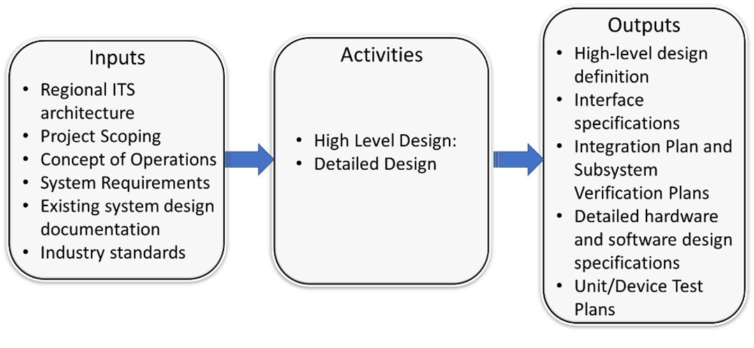
· Portion of the regional ITS architecture for the project · Project Scoping · Concept of Operations · System Requirements · Existing system design documentation · Industry standards |
|
PROCESS Key Activities |
· High Level Design: o Develop and evaluate high-level design alternative o Evaluate off-the-shelf components o Analyze and allocate requirements o Define interfaces and identify standards o Document high level design o Define integration plan and subsystem verification plans · Detailed Design o Prototype user interface o Develop detailed hardware and software design specifications o Select off-the-shelf (OTS) products o Create Unit/Device Test Plans |
|
OUTPUT Process Results |
· High-level design definition · Interface specifications · Integration Plan and Subsystem Verification Plans · Detailed hardware and software design specifications · Unit/Device Test Plans |
In the systems engineering approach, we define the problem before we define the solution. The previous processes have all focused primarily on defining the problem to be solved. The system design step is the first step where we focus on the solution. This is an important transitional step that links the system requirements that were defined in the previous process with system implementation that will be performed in the next process as shown in Figure 15.
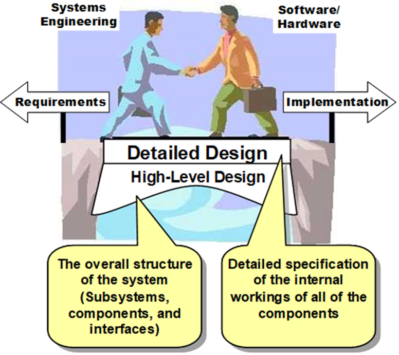
Figure 15: System Design is the Bridge from Requirements to Implementation
There are two levels of design that should be included in your project design activities:
High-level design is sometimes referred to as architecture definition in systems engineering handbooks and process standards. Architecture definition is used because an overall structure for the project is defined in this step. ISO/IEC/IEEE 15288 defines the purpose of architecture design as “the process … to generate system architecture alternatives, to select one or more alternative(s) that frame stakeholder concerns and meet system requirements, and to express this in a set of consistent views.” The alternative architectures often also represent different technologies, so that high-level design is sometimes also associated with technology selection.
System requirements from the prior section should be allocated to the architecture elements (or in some cases to multiple architecture elements working together as a subassembly. In some cases, if a requirement spans multiple elements, it may be useful to decompose the requirement into more primitive sub-requirements that can be allocated to specific architecture elements or modules. Since requirements are used to verify that the system components or modules are correct, the requirements allocated to a module should be completely satisfied by that correctly built module. Some requirements may require multiple modules working together to implement, and these requirements may be allocated to the multiple modules or subassemblies for testing during the later phases of integration.
Detailed design is the complete specification of the software, hardware, and communications components (and their various technology variants), defining how the components will be developed to meet the system requirements allocated to them. The software specifications are described in enough detail that the software team can code the individual software modules. The hardware specifications are detailed enough that the hardware components can be fabricated or purchased.
Design addresses all the requirements: The key risk being managed is that the system design does in fact address all of the requirements defined for the system. In other words, that all project requirements are satisfied by one or more project design technology specifications. A second risk to be managed is that the system design does not go beyond the requirements, which would likely entail additional cost and schedule for the system, which (along with scope and quality) systems engineering is seeking to control. This relationship between each system requirement and one or more design specifications is documented in a traceability matrix.
System design is a cooperative effort that is performed by systems engineers and the implementation experts who will actually build the system. The process works best when there is a close working relationship among the customer, the systems engineers (e.g., a consultant or in-house systems engineering staff), and the implementation team (e.g., a contractor or in-house team).
High-level design is normally led by systems engineers with participation from the implementation experts to ensure that the design is implementable. Typical activities of high-level design are shown in Figure 16. Each of the activities can be performed iteratively as high-level design alternatives are defined and evaluated.
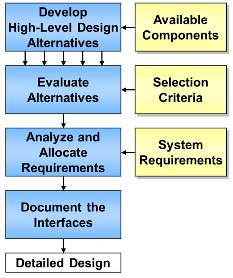
Figure 16: High Level Design Activities
(Source: FHWA)
Develop and evaluate high-level design alternatives
The system is partitioned into subsystems, and the subsystems are in turn partitioned into smaller assemblies. The process continues until system components – the elemental hardware and software configuration items – are identified. Figure 17 shows a partial decomposition of an electronic toll collection system that identifies all of the major subsystems and the components for the Video Enforcement subsystem.
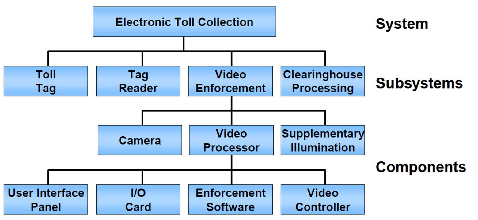
Figure 17: Electronic Toll Collection Subsystems and Components (Excerpt)
(Source: FHWA)
There are many alternative ways that a system can be partitioned into subsystems and components. In this Electronic Toll Collection example, we might consider whether the Clearinghouse Processing subsystem should be handled by a single centralized facility or distributed to several regional facilities. As another example, vehicle detectors could be included in the Video Enforcement subsystem or in the Tag Reader subsystem, or both.
Even a relatively simple traffic signal system has high-level design choices. For example, a traffic signal system high-level design can be two-level (central computer and local controllers), three-level (central computer, field masters, and local controllers), or a hybrid design that could support either two or three levels. High-level design alternatives like these can have a significant impact on the performance, reliability, and life-cycle costs of the system. Alternative high-level designs should be developed and compared with respect to defined selection criteria to identify the superior design choice.
One effective way to compare high level designs is to create a project architecture that highlights the subsystems and interfaces for each design. A regional ITS architecture may have project architectures defined that can serve as a starting point for the project architecture. In addition, the project definition from the regional ITS architecture can be imported into the Systems Engineering Tool for Intelligent Transportation (SET-IT), to create a more detailed representation of the projects systems and interfaces that are provided by the regional ITS architecture definition.
The selection criteria that are used to compare the
high-level design alternatives include consistency with existing physical and
institutional boundaries; ease of development, integration, and upgrading; and
management visibility and oversight requirements. One of the most important
factors is to keep the interfaces as simple, standard, and foolproof as
possible. The selection criteria should be documented along with the analysis
that identifies the superior high-level design alternative that will be used. If
there are several viable alternatives, they should be reviewed by the project
sponsor and other  stakeholders.
The USDOT regulation CFR 940.11 requires the systems engineering analysis for ITS projects to include an analysis of alternative system configurations.
Evaluate available components
One key aspect of high-level design is the identification of components that will be purchased, reused, or developed from scratch. The project may be required to use commerically-available hardware or software, or this may simply be the preferred solution. Specific design constraints may also require that a particular product be used. For example, a municipality that is expanding a signal control system that already includes 300 Type 170 controllers may constrain the design of the expansion to use the same controllers to facilitate operation and maintenance of the overall system. State DOTs and other large agencies often publish preapproved product lists that identify ITS-related products that meet agency requirements and/or specifications.
When commercially-available components will be used, the high-level design must be consistent with the capabilities of the target products. The designer should have an eye on the available products as the high-level design is produced to avoid requiring a design that can be supported only by a custom solution. A particular product should not be specified in the high-level design unless it is truly required. When possible, the high-level design should be vendor and technology independent so that new products and technologies can be inserted over time.
You should give commercially-available hardware and software serious consideration and use it where it makes sense. The potential benefits of off-the-shelf solutions – reduced acquisition time and cost, and increased reliability – should be weighed against the requirements that may not be satisfied by the off-the-shelf solution and potential loss of flexibility. If you have important requirements that preclude off-the-shelf solutions, determine how important they really are and what their real cost will be. This make/buy evaluation should be documented in a summary report that considers the costs and benefits of off-the-shelf and custom solution alternatives over the system life cycle. This report should be a key deliverable of the project design.
Also recognize that there is a large grey area between off-the-shelf and custom software for ITS applications. Every qualified software developer starts with an established code base when creating the next “custom solution”, accruing some of the benefits of off-the-shelf solutions. Many vendors of off-the-shelf solutions offer customization services, further blurring the distinction between off-the-shelf and custom software.
Analyze and allocate requirements
The requirements analysis described in Section 3.3.6 continues as the requirements are decomposed until there is enough granularity to allocate requirements to the system components identified in the high-level design.
The detailed functional requirements and associated performance requirements are allocated to the system components. To support allocation, the dependencies between the required system functions are analyzed in detail. Once you understand the dependencies between functions, you can make sure that functions that have a lot of complex and/or time-constrained interactions are allocated to the same component as much as possible. Through this process, each component is made as independent of the other components as possible.
Define interfaces and identify standards
Interfaces should be identified early, fully documented, and then managed throughout the project development. Interface specifications should be developed for external interfaces (i.e., interfaces between the current project and external systems) and internal interfaces (i.e., interfaces between project components). Interfaces between systems that are owned and operated by different agencies may require additional lead time to negotiate interface agreements.
This is the place to identify ITS standards and any other industry standards that will be used in detail. There are a variety of standards that should be considered at this point. Take a look at all interfaces, both external and internal. Since your regional ITS architecture and/or project ITS architecture was based on the Architecture Reference for Cooperative and Intelligent Transportation (ARC-IT), most interfaces should already have communications solutions--groups of standards that together satisfy the interfaces defined in your architecture. These solutions are defined to provide the most complete satisfaction of interface requirements, but might still have issues: mostly these will be gaps--areas where the solutions are incomplete, not fully tested or vetted. These are areas that researches and standards bodies might be working on, but point out areas where, if you are to implement, you will have additional work to do, particularly to ensure interoperability, a key issue for any interface to vehicles or handheld devices.
 Agencies are encouraged to incorporate the
ITS standards into new systems and upgrades of existing systems. The Regulation/Policy
requires the systems engineering analysis for ITS projects to include an
identification of ITS standards. Consult the ITS Standards Program website at https://www.standards.its.dot.gov/
for more information and available resources supporting standards implementation.
Agencies are encouraged to incorporate the
ITS standards into new systems and upgrades of existing systems. The Regulation/Policy
requires the systems engineering analysis for ITS projects to include an
identification of ITS standards. Consult the ITS Standards Program website at https://www.standards.its.dot.gov/
for more information and available resources supporting standards implementation.
Document High Level Design
The results of the previous activities will be collected into a key output of this step- the Project Design Document. There isn’t a single “best way” to present the high-level design to stakeholders and developers since different users will have different needs and different viewpoints. Over the years, high-level designs have evolved to include several different interconnected “views” of the system. Each view focuses on a single aspect of the system, which makes the system easier to analyze and understand. The specific views that are presented will vary, but they will typically include a physical view that identifies the system components and their relationships; a functional view that describes the system’s behavior; an information view that describes the information that will be managed by the system, and a communications view that defines the communications solutions (a related group of communications standards and specifications) that support each interface. As shown in Figure 18, these views are just different ways of looking at the same system.
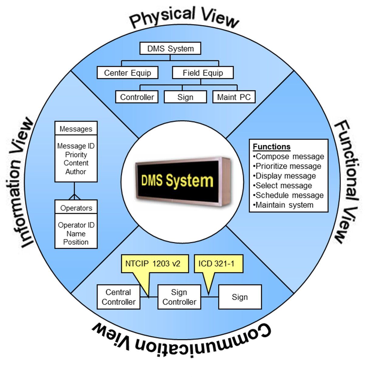
Figure 18: High-Level Design May Include Several Views
(Source: FHWA)
Create Integration Plan and Subsystem Verification Plans
An Integration Plan and Subsystem Verification Plans should be completed parallel with the high-level design. (See Section 3.3.9 for more information on integration and verification planning.)
Hardware and software specialists create the detailed design specifications for each component and software module identified in the high-level design. Systems engineers play a supporting role, providing technical oversight on an ongoing basis. As you might expect, the detailed design activity will vary for off-the-shelf and custom components, as shown in Figure 19.
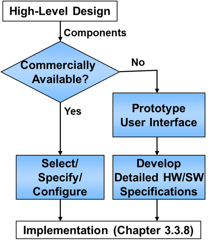
Figure 19: Detailed Design Activities
(Source: FHWA)
Prototype user interface
If a user interface is to be developed, a simple user interface prototype is an efficient way to design it. A prototype is a quick, easy-to-build approximation of a system or part of a system. A software prototype can be used to quickly implement almost any part of a system that you want to explore, but it is used most often to make a quick approximation of a user interface for a new system.
A user interface prototype should be employed to help the user and developer visualize the interface before significant resources are invested in software development. This is one area in particular where you can expect multiple iterations as the developers incrementally create and refine the user interface design based on user feedback. (You will find that it is often easier to get users to provide feedback on a prototype than on system requirements and design specifications, which can be tedious to review.)
While the user interface prototype is included here because it is an effective way to design the user interface, prototypes may actually be generated much earlier in the process, during system requirements development. The prototype can turn the requirements statements into something tangible that users can react to and comment on.
Develop detailed hardware component and software module design specifications
Detailed design specifications are created for each hardware component and software module to be developed. In the high-level design, each component is defined in terms of its allocated functional and performance requirements, with particular focus on its interfaces to external systems and other components.
The detailed design specifies exactly how the component will be implemented so that it meets the requirements. For hardware, mechanical and schematic drawings and parts lists are defined. For software, this includes specification of algorithms, data structures, and third-party software packages that will be used. For open ITS standards, this may include selection of optional standardized objects that together completely specify an interface MIB (Management Information Base).
The detailed design of each component should be reviewed to verify that it meets the allocated requirements and is fit for the intended purpose. Each specification of the detailed design specifications should be traced to higher-level requirements. This implies an expansion of the traceability matrix described under the Requirements process. Periodic or as-needed reviews can be held to monitor progress and resolve any design issues. For larger projects, coordination meetings should be held to ensure that concurrent design activities are coordinated to mitigate future integration risks. At the completion of the detailed design step, a broader stakeholder meeting is held to review and approve the detailed design before the implementation team begins to build the solution. A record of the technical reviews that were conducted should also be included in the project documentation.
Select off-the-shelf (OTS) products
One of the fundamental principles of systems engineering is to delay technology selection until you have a solid foundation for making the right choice. By waiting until this point in the process, the latest technologies and products can be considered, and these selections can be based on a thorough understanding of the requirements and the overall architecture of the system. The selections can also be made by specialists who are closest to the implementation and are therefore best equipped to make them. There are two fundamental ways that a product can be selected, depending on your procurement requirements and selected procurement strategy:
Specifications can be either performance-based or prescriptive. In a performance-based specification, you specify the functionality and the performance that are required rather than what equipment to use. In a prescriptive specification, you specify exactly the equipment that you want. A performance-based specification for a dynamic message sign would include statements like “The sign shall provide a display of 3 lines of 25 characters per line.” A prescriptive specification would be “The Trantastic LED Model XYZ sign shall be used.” Performance-based specifications tend to provide the best value because they allow the contractor or vendor maximum flexibility to propose the best solution that meets your specifications.
If a trade study is performed, then the functional, performance, and environmental requirements that are allocated to the component or module should be used to define product selection criteria. An alternatives analysis document captures the alternatives that were considered and the selection criteria that were used to select the superior product. Existing trade studies, approved product lists, and other resources can be used to facilitate product selection. The evaluation of off-the-shelf products should be reviewed to verify that the evaluation criteria were properly defined and applied fairly and that an appropriate range of products was considered.
Create Unit/Device Test Plans
Test plans should be created for each hardware component and software module to test all requirements identified in the HW/SW design specifications. The test plans will show how each design specification will be verified.
The level of each activity should be appropriately scaled to the size and budget of the project. For example, a small project may have an analysis of alternatives that is only a page or two long, based upon qualitative comparisons. Constraining the number of sub-systems will also reduce the effort here and in the subsequent steps, such as integration and verification.
This activity is driven by the amount of custom development needed for the project. The more customized the development, the more effort there is at this step. For small systems that contain nearly all products previously used by the agency to address similar requirements, the primary activity is the evaluation of these products.
The FHWA Regulation requires requirements to be developed for ITS projects funded with the Highway Trust Fund, including the Mass Transit Account. It also requires the analysis of alternative system configurations to meet requirements.
The IEEE 1233 Guide for developing system requirements specifications provides a standard for developing requirements.
The FHWA Regulation does not specifically mention component level detailed design practices to be followed. For software, IEEE/ISO 12207 Software Life cycle process provides specific process guidance.
Table 7 identifies that the high level and detailed design specifications trace back to the system functional, performance and environmental requirements, and forward to the component, module, and interface tests.
Table 7: Design traceability
|
Traceable Artifacts |
Backward Traceability To: |
Forward Traceability To: |
|---|---|---|
|
High-Level Design |
System Requirements |
· Detailed Design Specifications · Verification Tests |
|
Detailed Design Specifications |
· High Level Design · Allocated Requirements |
· HW/SW Implementation · Verification Tests |
The following checklist can help answer the question “Are all the bases covered?” once the activities above have been planned or performed. The checklist is not sufficient by itself.
High-Level Design
R Were alternative project architectures/high level designs considered?
R Is there documented rationale for the selected project architecture/high level design?
R Are all interfaces identified and documented?
R Have industry standards been identified for the high-level design?
R Is the design clearly documented?
R Is the high-level design traceable to the system requirements?
R Do any of the requirements need to be changed based on the high-level design development effort?
R Have the integration, verification, and deployment plans been updated in the SEMP?
Detailed Design
R Did each component have a technical review?
R Did each component design trace to a sub-system requirement?
R Were all sub-system requirements satisfied by the component design activity?
R Was a verification plan for each component defined?
R Was each component design checked for performance?
R Was the component design documentation complete, up to date, and accurate?
R Was a critical design review conducted?
R Was an alternatives analysis done on the products used in the system?
R Have all system and sub-system requirements been updated at the time of the critical design review?
| Related: |