| 10.1 Chapter Overview |
Chapter 10 provides guidance to practitioners who are ready to plan, design, and implement the systems and field elements within individual capital improvement projects that, wholly or in part, support the ramp management strategy selected in Chapter 6. This chapter supplements Chapter 7, which focused on the implementation of the overall ramp management strategy, by addressing specific issues and activities practitioners should consider when implementing smaller, individual capital projects that support the overall ramp management strategy discussed in Chapter 7. This information will help practitioners develop a comprehensive understanding of project planning and design, and it will help ensure that projects are implemented successfully.
Chapter 10 focuses on putting the capital improvement project into place. Once the internal decisions have been made about specific ramp management strategies, staffing within the organization, and system operation and maintenance, the agency can begin the planning and design process. One should understand that no agency can or should implement all of their ramp management activities at once – it takes an ongoing capital improvement process to install the equipment and make required geometric and roadway revisions that support and enable the implementation of ramp management strategies. The system is built in pieces, and many capital projects will be required to realize the agency’s overall vision for ramp management. Because this may occur over several funding cycles, the Traffic Manager must ensure that the decisions that were made early on (initial visioning and conceptualization) are periodically revisited. This will allow the capital improvement projects to be consistent with what has been agreed upon, and to be updated to reflect any policy or technology changes. It is important to verify that the ramp management system concept is up-to-date and correct.
The second step in this phase involves applying the best practice for designing and building these pieces of the overall vision. Because the individual capital projects are implemented over time, they must be designed and constructed according to the best practices at the time.
This chapter begins with the environmental review process and by identifying alternatives and key impacts. As part of the design process, a set of alternatives may be selected for evaluation. The alternative analysis process is often required in the environmental review, which helps to ensure that the design is the most appropriate in terms of costs (capital, operations, and maintenance) and impacts on traffic operations, air quality, equity, and surrounding neighborhoods. The next step of this process involves understanding the various operational considerations when implementing ramp management strategies. There are general design considerations, as well as considerations that pertain to the specific ramp management strategy, such as ramp closures or terminal treatments. Finally, the chapter ends with a discussion on planning high-level design for the Intelligent Transportation System (ITS) infrastructure needed to support ramp management strategies.
Chapter 10 Objectives:
- Objective 1: Understand that the decisions made during conceptualization need to be revisited at the beginning of the development of a capital improvement project and potentially updated.
- Objective 2: Be aware of issues that may be encountered during environmental or project review that are specific to ramp management strategies.
- Objective 3: Become familiar with the design considerations for implementing ramp management strategies.
- Objective 4: Identify and understand ramp management hardware and ITS infrastructure needs.
|
| 10.2 Environmental Review for Ramp Management Projects |
An environmental review is a public process for examining potential significant impacts of major development projects. State agencies are given an opportunity to comment and supply environmental resource information on projects at the earliest possible stage in project development. This process affords the Project Manager and Project Designer time to avoid or minimize potential impacts in the design process. The review examines the impact on the environment and includes consideration of traffic, air quality, noise and vibration, and other factors. It also typically identifies any needed environmental remediation for the site.
The majority of the smaller projects will likely be exempt from the environmental review process. In Oregon, ramp metering projects are categorically excluded from any sort of environmental process because they are deemed not to have a significant effect on the human environment. This may vary from state to state. Agency policies or public concern may require some type of less formal environmental review. Although perhaps not as comprehensive as an Environmental Impact Statement (EIS) or Environmental Assessment (EA), some type of environmental review may be conducted. [1], [2] Figure 10-1 shows a graphic representation of the National Environmental Policy Act (NEPA) process.
As an example of the EA process, Sound Transit in Seattle, Washington had a project that called for the implementation of 14 exclusive, direct-access High-Occupancy Vehicle (HOV) ramps in the region to improve regional and local bus service. These ramps were identified as the preferred investment for improving transit speed and reliability, by eliminating the need to weave across general-purpose lanes of traffic to reach HOV lanes. The master agreement with the Washington State Department of Transportation (WSDOT) divided the ramps into four Regional Express capital project groupings with three phases each. Phase 1 dealt with the preliminary engineering and environmental design component. Phase 2 encompassed plans, specifications, and estimates (PS&E) and right-of-way acquisition. Phase 3 handled bidding and construction management. Following the system-level alternatives analysis, the environmental review consisted of a NEPA EA for HOV Access and for Park-and-Ride facilities. The draft environmental document was reviewed by the Federal Highway Administration (FHWA), Federal Transit Administration (FTA), and WSDOT and then was circulated for public comment. After the EA was issued and approved, it was adopted for compliance with the State Environmental Policy Act (SEPA). Staff were then able to proceed with final design and right-of-way acquisition. [3]
Figure 10-1 : NEPA Process Overview [4]
|
| 10.2.1 Identifying Alternatives |
|
|
| |
| An alternatives analysis should be conducted as part of the environmental review process prior to the design of an individual capital project. The analysis should address project design alternatives, rather than review alternative programmatic solutions to the same problem. In other words, the decision on the ramp management strategy has been made and an analysis of the different possible design and operational approaches is the next step. The process used to select the preferred ramp management strategy was discussed in Chapter 6. The results from that decision-making process are valuable information that should be considered when reviewing the trade-offs among the various design alternatives.
In the environmental review stage, an alternatives analysis must occur at the project level. The programmatic-level decisions made in Chapter 6 should be reviewed to verify that conditions have not changed that would lead to revising the overall ramp management strategy. Alternative designs should address key impacts such as equity and traffic impacts. Depending on the level of environmental review and potential impacts, the agency may decide to bring forward new alternatives or potential solutions to the problem not considered or selected previously. |
| 10.2.2 Key Impacts of Ramp Management Strategies |
|
|
Traffic Impacts and Associated Effects
One component of an environmental analysis is the evaluation of traffic impacts. Once a number of design alternatives are developed that will address the need, a detailed analysis is conducted to evaluate the differences among them, as compared to the ”No Action” (or “Do Nothing”) alternative. Elements such as traffic volumes, level of service, traffic-related noise, and vehicle emissions are modeled in the various alternative scenarios along with the potential improvements to mitigate the traffic impacts.
For example, some of the factors that are generally evaluated in a traffic analysis are traffic volumes, vehicle-miles of travel (VMT), level of service (LOS), and vehicle-hours of travel (VHT). Other factors such as noise levels and vehicle emissions are also evaluated. For the issues that often come up with ramp management projects, there are additional analyses that should be included, such as:
- Ramp delays and queuing.
- Travel times on the freeway and adjacent arterial network.
- Traveler safety.
- Diversion or traffic pattern changes that affect neighborhoods or local businesses.
The analysis needs to address both the freeway facilities and the local streets and arterials that may be affected by the ramp management project. It is important to consider how ramp metering will affect travel patterns on facilities neighboring the freeway. Ramp delays and queuing may cause changes in overall travel patterns as some drivers will change their route or time of travel to avoid the worst queuing conditions. Estimates of change in volumes and overall traffic conditions for both freeways and arterials are important impacts to be assessed at this stage of the project.
The results of the traffic analysis will serve as inputs to other impact assessments as well, such as air quality, noise impacts, and additional impacts to the surrounding area.
The results of the environmental review are not meant to approve or deny a project, but rather to be used as a source of information to guide approval decisions. In other words, the analysis can point out the problems and potential solutions.
Impacts on Surrounding Areas
If drivers change their travel behavior due to a ramp management project, traffic patterns will change and there could be significant impacts on the surrounding area. Changes in travel behavior and traffic patterns may affect arterial operations and traffic on local or residential streets. If the changes in traffic patterns are significant, area businesses may be affected, especially if the businesses’ customers rely on on-street parking or pedestrian movements for access. Residential areas may experience increases in traffic that local residents find unacceptable.
During the environmental review phase of the project, impacts on streets adjacent to and affected by the freeway, neighborhood traffic patterns, and businesses in the affected area need to be analyzed. The traffic analysis discussed above should estimate the changes in traffic patterns that can be used to analyze the impacts on the surrounding areas.
Given existing traffic patterns and estimated changes to traffic patterns in the area, impacts on street operations can be analyzed using a variety of traffic analysis tools, such as those discussed in Chapter 9. As the traffic impact analyses are conducted, it is a good idea to coordinate with the local agencies that are responsible for the operation of the roadways in question. Coordination with the operating agencies was likely initiated during the initial outreach efforts described in Chapter 7. The agencies should be familiar with ramp management strategies, and the coordination needed to ensure accurate impact assessment of the surface street network.
Neighborhood and business impacts may be driven strongly by emotion and perceptions of the impacts on traffic speeds, volumes, or other operations. It may be difficult to convince neighborhood residents and business owners that impacts in their area will not be significant. It is important to provide these stakeholders with an opportunity to voice their concerns early in the analysis and for the analysis to be flexible enough to address these concerns. One effective strategy is to present system impact studies from similar areas to show stakeholders and neighborhood groups the types of impacts to expect.
Equity
Environmental justice is a doctrine in many existing laws and policies (e.g., the Title VI of the Civil Rights Act of 1964 and most recently the Safe, Accountable, Flexible, Efficient Transportation Equity Act: A Legacy for Users (SAFETEA-LU)). A 1994 Presidential Executive Order directed every federal agency to make environmental justice part of its mission by identifying and addressing the effects of all programs, policies, and activities on minority and low-income populations. [5 ] Environmental justice is based upon three fundamental principles:
- To avoid, minimize, or mitigate disproportionately high and adverse human health and environmental effects, including social and economic effects, on minority and low-income populations.
- To ensure full and fair participation by all potentially affected communities in the transportation decision-making process.
- To prevent the denial of, reduction in, or significant delay in the receipt of benefits by minority and low-income populations.
When properly implemented, these principles will improve all levels of transportation decision-making. They will allow better transportation decisions that meet the needs of all people; help design transportation facilities that fit more harmoniously into communities; and enhance the public involvement process and strengthen community-based partnerships. These principles will also improve data collection and analysis tools that assess the needs and impacts on minority and low-income populations; and avoid disproportionately high and adverse impacts on these groups.
When closing ramps, implementing ramp metering, or implementing special-use treatments on ramps, equity issues must be addressed. The agency must ask the following questions:
- Which geographic areas benefit the most?
- Which have the most impacts?
- Who gets the most from the strategy?
- Who may be negatively affected?
In an environmental justice review, the analysis must assess the impacts on disadvantaged groups. This includes drivers as well as surrounding residents and workers in a given area. For example, public outreach activities need to ensure that there is meaningful participation of minority and low-income populations. If barriers exist, they must be removed so these groups will become engaged to be a part of the transportation decision-making process. [5] Agencies must develop the technical ability to assess the benefits and adverse effects of transportation activities on different groups.
Of particular concern is the potential for a distribution of benefits to suburban groups at the expense of urban dwellers. For example, some believe that ramp metering is advantageous for longer trips on the system (at the expense of the shorter trips). Residents who live closer to urban centers are subject to the delays of ramp metering, and do not receive immediate access to the freeway. Suburban commuters who live outside of the metered zone can receive all of the benefits without any of the ramp delays. [5] This is an important issue to consider when implementing ramp metering.
Each agency can address the equity issue using a variety of techniques. The following are two examples using time-of-day restrictions and metering rate modifications. In Detroit, Michigan, the ramps were only metered in the outbound direction (away from the Central Business District (CBD)) to minimize the city-suburb equity issue. Once motorists understood how effective ramp metering was, the system was expanded with fewer objections. In Seattle, Washington, WSDOT used a different approach by implementing more restrictive metering rates further away from the CBD. Suburban motorists had the most to gain from improved freeway performance, so this minor additional delay more than offset the reduced mainline travel time.[5]
The equity issue also applies to other ramp management strategies. For example, with ramp closures, the agency must ensure that any affected low-income and minority populations are given a fair opportunity to provide input into the public process. Ramp closures can have extreme impacts, so other strategies should be examined before this strategy is selected. The public involvement activities need to be adapted to the characteristics of the particular stakeholder community. For example, to encourage more local participation and increase attendance, community meetings with hand-delivered notices and a local venue are sometimes needed.
Air Quality and Noise Impacts
The final key impacts that should be considered in the environmental review of a ramp management project involve air quality and noise issues. For air quality, the concerns will primarily be about creating air quality “hot spots” (an isolated location with a significant air quality problem) on ramps with queued vehicles. Corridor-level air quality is often improved with more stable traffic flows and fewer accelerations and decelerations. However, inherent in ramp metering is forcing vehicles to wait to get onto the freeway, creating acceleration and deceleration maneuvers on the ramps. It is important to take air quality hot spots into account in the environmental review process and in the air quality analysis for the ramp management project.
Noise impacts should be estimated for ramp management projects, especially for those that include ramp metering. The primary issue to be addressed with noise impacts is noise from vehicles quickly accelerating from a stopped condition. This situation may be worsened on an uphill ramp with high truck percentages located adjacent to a neighborhood, school, hospital, or other noise-sensitive area. |
| 10.3 General Operational and Design Considerations for Ramp Management Projects |
There are a variety of operational and design considerations that must be taken into account when developing and implementing a capital project. In addition to understanding the needs of a particular ramp, corridor, or freeway system, several other factors need to be addressed when planning for ramp management and control strategies. These considerations follow.
Corridor Objectives: This involves reviewing operational considerations and aspects that may influence the project design. The process for selecting ramp management strategies conducted in Chapter 6 must now be translated into design elements. In other words, each operational objective must be understood and incorporated into design criteria to ensure that a designer will understand how to properly address operational objectives in the design.
Operational objectives for the corridor(s) in question should be established. These objectives should be based on the regional goals for a facility, if they exist. Corridor objectives can include:
- Reducing delay for transit and HOV vehicles..
- Balancing ramp delay with freeway delay, or balancing freeway operations with the operations of arterials and other surface streets.
- Reducing crash rates.
These objectives should be reviewed prior to planning, design, and implementation to ensure that projects will be developed with the specific corridor objectives in mind.
Overall policies for ramp management should also be established. For ramp metering, these policies would address issues such as hours of operation, implementation thresholds, and performance policies.
Project Consistency: If the capital project being planned and designed includes more than implementation of ramp management strategies, it is important to make sure the various pieces of the project are consistent with one another:
- Review overall project objectives for consistency.
- Ensure that the project can be staged to keep all investments viable through construction. This involves making sure that construction mitigation elements of ramp management can be operated during construction. It also requires that construction activities that may disrupt critical ramp operational components, such as surveillance and ramp metering, have mitigation planned in the project. The mitigation may include keeping existing systems operational during construction or installing temporary systems for the construction period.
- Review all aspects of the capital project to make sure that physical and geometric revisions of the various components are consistent and support ramp management strategies.
Maintenance: As with virtually any new system, installing new equipment, pavement markings, or signing will have a maintenance impact. Maintenance staff should be consulted early on to determine if they have any input or concerns about the ability to maintain any elements installed as part of ramp management and control. For example, the maintenance staff may have comments regarding the ability to keep equipment manufacturers consistent. Typically, they want to reduce the number of different manufacturers’ equipment for the same type of item, because this reduces the required number of spare parts and training manuals, and reduces the time to train staff. They may also have insight as to the pros and cons of a specific type of manufacturer because they work with the field devices on a daily basis.
Other issues such as the location of equipment should also be discussed. Maintenance staff will want to give their recommendations so that they have adequate space to park their maintenance vehicles and can ensure their safety while servicing equipment. Equipment location also plays into ease of access. Depending on the level of maintenance required for a particular item, the ability to access and repair a piece of equipment can be critical. |
|
The design of ramp management elements should conform to the American Association of State Highway and Transportation Officials (AASHTO) [6] standards and the FHWA's Manual on Uniform Traffic Control (MUTCD) [7] recommendations for freeway facilities, unless deviations from these standards can be justified according to specific agency guidance and procedures. These guidelines include elements such as geometric design (horizontal and vertical curvature); cross-slopes and drainage design; signing and striping; traffic signal design and operations; and other aspects that must be addressed in the final design. Some projects may require ITS systems. State Departments of Transportation (DOT) generally have their own design standards that are provided in design manuals or other documents. Practitioners should conform to the agency-specific design guidance as well as the national standards.
Many agencies use the basic implementation guidelines that are outlined in the MUTCD, while others have developed specific design standards and guidance for ramp management. One example is the Ramp Meter Design Manual from Caltrans [8]. This document contains design criteria for storage requirements, acceleration lanes, stop bar location, and meter locations; hardware criteria for signal heads, detector loops and the controller cabinet; and information for signing and pavement markings. Another example is the WSDOT guidelines outlined in their WSDOT Design Manual, (Section 860).13 Additional information can also be found in WSDOT’s HOV Design Guide.14 Agencies should consider developing their own design standards if they intend to implement ramp management to any significant scale. Agencies developing their own design standards may benefit from reviewing those developed by other agencies. |
|
Effective ramp management and control strategies are dependent on motorist compliance. For example, in the case of ramp metering, it should be made clear that ramp meter signals are traffic control devices and should be obeyed just as any other intersection traffic signal. This should be clearly communicated as part of the public information effort. The laws and associated penalties must be explained. As such, a coordinated effort with local law enforcement must also be a part of the implementation. Effective enforcement requires a variety of elements, including; good enforcement access, a safe area to cite violators, adequate staff, support by the courts, and well-designed signs and signals that are enforceable. Motorist compliance is critical to the success of a ramp management system.[9]
Appropriate enforcement elements must be designed into the project, because police need safe and effective locations in order to monitor and enforce compliance. Specifically, this means eliminating the potential for officers to get struck by a motorist when making enforcement contacts or in any other aspect of their duties. Law enforcement agencies that have enforcement jurisdiction in the project area should be consulted in the project development and design stages in order to gain their input and buy-in. Working jointly, agency staff can determine the appropriate design elements, such as the number and design of enforcement areas.
Coordination efforts with state and local law enforcement agencies should also involve developing an enforcement strategy. For example, enforcement considerations for an HOV bypass lane include:
- How will enforcement be used to prevent Single-Occupant Vehicles (SOVs) from using the HOV bypass lane?
- What are the goals of enforcement (i.e., safety or equity)?
- How do the goals relate to or affect the frequency and approach to enforcement?
For law enforcement, this can mean an increased caseload from HOV violations in traffic court and should be balanced with their other duties. Agency staff should work jointly with law enforcement to develop an enforcement strategy. More information on HOV enforcement can be found in the HOV Systems Manual [10] |
| 10.3.3 Performance Monitoring |
|
|
During the development and design of a ramp management project, it is important for project planners and designers to be familiar with the measures used to monitor the performance of ramp management strategies. Chapter 9 covers performance monitoring in detail and suggests that a performance monitoring and reporting system be in place for ramp management strategies. Systems and processes must be implemented to ensure that ongoing performance measurement can be easily and efficiently conducted. Project planners and designers can facilitate performance measurement and monitoring by incorporating data collection equipment into the design of projects that implement ramp management strategies.
Various types of equipment can be used to conduct performance monitoring. These include data stations, video or radar detection, loop detection, or Global Positioning System (GPS)-equipped travel time runs. With these devices, measurements of travel times, vehicle speeds, traffic counts, or vehicle conflicts can be easily obtained. |
| 10.4 Specific Design Considerations for Ramp Metering |
This section discusses specific design considerations for ramp metering. The information included was taken from a variety of ramp metering design manuals or design guides. Several are referenced at the end of this chapter, including those from Caltrans, WSDOT, and the Minnesota DOT (Mn/DOT). Other states also have design guides or manuals for ramp metering. If the agency developing a ramp metering project does not have design guides or manuals that are relevant, the documents from other agencies should be reviewed to see which ones provide the best fit. In the following sections, the Caltrans Ramp Meter Design Manual is most often cited because it has very comprehensive coverage of ramp metering elements in a single document and because Caltrans has extensive experience in designing and operating ramp meters. |
|
Ramp meters can be installed on existing or newly constructed ramps. Each design element identified in this section should be considered, whether for new ramp construction or an existing ramp being retrofitted with a ramp meter. Figure 10-2 shows basic ramp meter elements. This graphic shows the ramp meter location in relation to the stop bar and the general layout of loop detectors needed to support ramp metering.
Figure 10-2 : Ramp Meter Elements [11]
Location of Ramp Meter
The location of the ramp meter, and therefore the stop line, needs to be located to achieve a balance between queue storage space and acceleration distance to the freeway. In other words, locate the ramp meter so that it maximizes the available storage but also allows sufficient acceleration distance for a vehicle to safely merge onto the freeway from a stopped condition at the ramp meter. Queue storage requirements can be calculated using a range of simple to complex traffic analysis tools (refer to Chapter 9 for more information). Queue lengths can also be roughly estimated by subtracting the metering rate from the ramp volume over a specific time period. Acceleration distance can be calculated using AASHTO standards.
Number of Lanes
The number of needed ramp lanes should be based on the ramp volume, required queue storage, meter release rate (either one or two vehicles allowed per green), and available ramp width. Available ramp width may be based on the existing ramp pavement or the pavement width feasible based on geometrics and topography. Shoulders may also be utilized when ramp meters are operating, to increase the number of effective lanes and thereby increase the queue storage capacity. The estimated queue and available storage distance to the upstream intersection will have an influence on the number of lanes needed.
In general, the maximum discharge rate of a single metered lane is 900 vehicles per hour (veh/h). This is calculated using a minimum cycle time of four seconds (2.5 seconds of red plus 1.5 seconds of green). The lowest practical discharge rate is 240 veh/h, which is based on a 15-second cycle time.[12] Refer to Table 10-1 for general guidelines on the appropriate number of metered lanes and release rate based on the ramp volume.
Table 10-1 : Appropriate Number of Metered Lanes and Release Rate Based on Ramp Volume*
| If ramp volume is… |
…then consider this number of metered lanes |
…with this release rate. [N] |
<1000 veh/h |
One lane |
Single |
900 – 1,200 veh/h |
One lane |
Dual |
1,200 – 1,600 veh/h |
Two lanes |
Single |
1,600 – 1,800 veh/h |
Two lanes |
Dual |
|
Note. Single release rate allows one vehicle per green cycle, and dual release rate allows two vehicles per green cycle.
Single-Lane Metered Design
Single-lane ramp designs should accommodate a minimum width and distance between the stop line and freeway entrance. Caltrans recommends a single-lane metered ramp to have a 3.6-meter (11.8-foot) pavement width for the traveled way, 1.2-meter (3.9-foot) inside shoulder width, and 2.4-meter (7.9-foot) outside shoulder width.8 The operation can allow for one vehicle per green or multiple vehicles per green depending on the desired flow rate.
Multi-Lane Metered Design
Multi-lane ramp designs can be used to increase the overall vehicle storage within the available ramp length or to accommodate demands that exceed the capacity of a single metered lane. This design requires not only adequate acceleration distance from the stop bar to the freeway entrance, but also adequate distance for the multiple lanes to merge prior to the freeway entrance.
Multi-lane metered designs can release vehicles simultaneously (alternating between the lanes), or they can operate independently of one another. With multiple lanes, it is possible for each lane to operate with a different metering rate.
Ramp Design Speed
The design speed for a ramp is based on the design speed for the freeway mainline. For example, WSDOT follows the guidelines shown in Table 10-2.
Table 10-2 : Sample Ramp Design Speed[13]
| Freeway Mainline Design Speed km/h (mi/h) |
64.4 (40) |
80.5 (50) |
96.6 (60) |
112.7 (70) |
128.8 (80) |
Ramp Design Speed km/h (mi/h) |
56.4 (35) |
72.5 (45) |
80.5 (50) |
96.6 (60) |
112.7 (70) |
|
Queue Management
Required queue storage is based on the ramp volume, metering rate, release rate, and vehicle length. As an example, Mn/DOT uses a general rule of 10 percent of the pre-metered peak hour volume.12 Thus, if the peak hour volume is 500 veh/h, storage for 50 vehicles should be sufficient. This storage requirement can then be converted from vehicles to distance by multiplying the vehicles required by the average vehicle length (this can be estimated at 25 feet or calculated through field measurements). It is desirable to contain the ramp meter queue within the limits of the ramp. However, there are times when the queue may extend beyond the available ramp storage. In these situations, there are several methods for handling the additional overflow queues:
- Provide additional storage on surface streets. In San Diego, storage is not limited to the ramp. A portion of the surface street is used to store vehicles from the ramp queue. This requires traffic signal retiming at nearby intersections to reduce the impact of the ramp queue on non-freeway-bound traffic.
- Adjust the metering rate to reduce the queue. This will have a negative impact on the freeway operation, but it will prevent the queues from disrupting local arterial operations. When reducing the queue, it is important not to “dump” the entire queue onto the freeway in order to relieve the backup.
There are various locations where detection can be used to assist with queue management (i.e., mid-ramp and end-ramp detection). Ramp queue detection is used to monitor the queue length and adjust the metering rate prior to the queues becoming excessive. It is beneficial to install this additional detection because it allows the agency to monitor and reduce the queues before they cause operational problems.
- Allow platooning. Platooning permits two or three vehicles per green (two vehicles per green is also referred to as a dual release rate). Allowing two vehicles per green can increase the practical limit of a single-lane on-ramp from 900 to approximately 1,200 veh/h (see Table 10-1).
- Provide driver information. Some traffic will naturally divert because of ramp metering and seek routes without queues or meters. There are some ways to inform drivers of the delays so that they can make an informed choice. Where queuing is more severe, an active management approach can be taken to address the queuing with signs upstream of the ramp that inform motorists of the traffic delay. For example, a Dynamic Message Sign (DMS), with the specific delay time or a simple blank-out sign, could be activated when the queues are unacceptable.
HOV Bypass Lanes
HOV bypass lanes are a special-use ramp treatment, as previously discussed in Section 5.5. Adding an HOV bypass lane not only encourages HOV use, but also proportionately reduces the ramp meter queues (HOVs typically make up anywhere from 10 to 25 percent of the traffic volume12). This separate lane is typically designed to allow HOVs to bypass the general purpose lane(s) and the ramp meter. Figure 10-3 shows a two-lane metered ramp with an HOV bypass lane. The bypass lane can be used for transit vehicles only or all HOVs. This design element should only be considered if there are policies in place to support HOV and is part of a broader HOV plan.
If dual left-turn lanes from an arterial feed an on-ramp with a single metered lane and an HOV lane, the agency must consider the most appropriate lane allocation for the left-turn lanes. If there are a considerable number of HOVs in the left-turning traffic stream, the left-turn lane directly feeding into the HOV lane could be designated for HOVs only during times when the ramp is metered. This lane assignment would provide easier access to the HOV bypass lane and reduce weaving on the ramp. If the ramp has sufficient length and the left turns have a lower HOV volume, another option would be to keep both arterial dual left-turn lanes open to all vehicles and provide for sufficient merging to the HOV lane on the ramp itself.

Figure 10-3 : Example HOV Bypass Lane [14]
Consideration should also be given to right-turn movements from the arterials to the ramp, especially in deciding which of the two ramp lanes should be designated as the HOV lane. If there is a large volume of right-turning traffic with significant HOV volumes, the agency should select the configuration that will minimize HOV delay and weaving in general. If the right lane from the arterial is a drop lane to the ramp, then the HOV lane should be located on the right side to prevent the high volumes of HOVs from weaving. On the other hand, if there are minimal HOV volumes, then the rightmost through lane could be designated as a through lane and right-turn lane for HOVs only. In this case, the left lane on the ramp should be designated as the HOV lane.
For more information on HOV and other special-use treatments, see Section 10.6.
Enforcement Areas
As discussed in Section 10.3, enforcement should be coordinated with the local and state enforcement agencies during the planning and design phase. Design features such as the number of enforcement areas and their locations and dimensions should be discussed and agreed upon. Enforcement areas may be on the ramp itself or in a nearby area with line-of-sight to the ramp meter. Figure 10-3 shows the general location of an enforcement area on a ramp.
On single-lane ramps, a paved enforcement area is not necessary, but the area should be graded to facilitate future ramp widening. The enforcement area should be located on the right side for queue bypasses and downstream from the stop bar so that the officer can be an effective deterrent. The overall length of the enforcement area may be adjusted to fit the specific conditions on the ramp.[15]
Freeway-to-Freeway Metering
Freeway-to-freeway metering consists of metering a ramp that connects one freeway to another. It is critical in this high-speed environment that adequate sight distance and sufficient advance warning be provided to motorists, as they will likely not be expecting to stop. Figure 10-4 shows an example of freeway-to-freeway metering in Portland, Oregon.
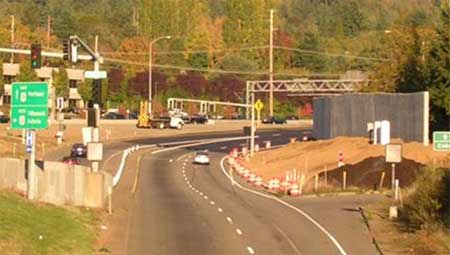
Figure 10-4 : Example of Freeway-to-Freeway Metering
Another example of this application is in San Diego, California, where its first use was in 1971. Since then, three more installations have been constructed. One application was implemented in 1978 to relieve congestion and queuing through the interchange. The meter uses an automated, traffic-responsive algorithm that turns the meter “on” during periods of heavy congestion, which is typically only during the peak periods. All three lanes on the ramp are metered (two general-purpose lanes plus an HOV lane). At start-up, the ramp carried 1,900 veh/h during the peak hour with a maximum delay of about three minutes. Currently, the ramp accommodates 2,900 veh/h with a maximum delay of approximately 10 minutes.[16] Despite the relatively high ramp delay, there have been very few complaints. Caltrans believes that this is due to the high level of service provided on the freeway and, in particular, the high speeds that are maintained beyond the meters. Travel time savings are estimated to be up to 20 minutes for certain home-to-work commute trips.[16]
Some suggested policies for the use of freeway-to-freeway ramp metering, as outlined by WSDOT, include: [16]
- Implement at locations where recurring congestion is a problem or where route diversion (to suitable alternative routes) should be encouraged. For example, install meters on freeway-to-freeway ramps where more than one ramp merges together before feeding onto the mainline, and where congestion on the ramps occurs regularly (i.e., four or more times a week).
- Install to improve the freeway mainline flow and on-ramp merge or to help multiple ramps merge into one ramp. Verify with analysis prior to installation.
- Avoid metering vehicles twice within a short distance (i.e., three miles).
- Avoid metering single-lane, freeway-to-freeway ramps that feed traffic into an add-lane, because this underutilizes the 2,000 veh/h capacity of the add-lane by metering at the typical rate of 900 veh/h.
- Monitor and control all freeway-to-freeway ramp meters from a central location, such as a Traffic Management Center (TMC).
- Install meters at locations on roadways that are level or have a slight downgrade so heavy vehicles can easily accelerate. Also, install meters where the sight distance is adequate for drivers approaching the meter to see the queue in time to safely stop.
|
|
Ramp meter hardware consists of a ramp controller, signal heads, signal pole(s), and detection devices.
Ramp Controller
The controller assembly consists of a cabinet, controller, load switches, input files, loop amplifiers, and other devices similar to a traffic signal at an intersection. The ramp controller typically acts as a data station as well as a signal controller. The most common ramp controllers are type 170s or type 2070s. The 170s are microprocessor-based devices that control the ramp meter signals using information from the loop detectors. The 2070s provide similar functions to the type 170s and are more powerful VME-based (Versa Module Eurocard) controllers with 16-bit microprocessors that provide additional functionality to the older 170s. Figure 10-5 shows the back-top view of a 2070V unit with an additional 7a card installed and the top cover of chassis removed.
Other necessary features include the ability to provide accessible power source and communication with the TMC. Communication can be provided via telephone lines, fiberoptics, microwave, or radio frequencies (RF).
The controller cabinet must be placed where it is easy to access for maintenance, allows a technician to see the signal heads, does not block a vehicle’s sight distance, and is protected from errant vehicles.

Figure 10-5 : Type 2070V Controller [17]
Signals
For single-lane ramps, a Type I signal pole (vertical pole only) with two signal heads should be located on the left side of the ramp, adjacent to the stop line. For two-lane ramps, a Type I signal pole can be located on each side of the ramp or a mast arm-style signal pole with overhead signal heads can be used. For three-lane ramp meters, a mast arm signal pole should be used. All signal poles should be located in a clear zone to reduce the potential for “knock-down.”
The FHWA’s Manual on Uniform Traffic Control Devices (MUTCD) provides standards for placement and location of all traffic signal devices.7 Practitioners should refer to Sections 4D and 4H of the latest edition for updated guidelines. An FHWA official interpretation of this section of the manual dated September 30, 2005 recommends that for multi-lane metering where staggered or independent release is used, two signal heads per lane should be used.[18]
Mast Arm Signal Pole Requirements:
- The distance from the stop line to the signal faces shall not be less than 12 meters (40 feet) or more than 55 meters (180 feet), unless a supplemental near-side signal face is provided.
- The height of the signal housing over the roadway shall not exceed 7.8 meters (25.6 feet).
Signal Head Placement:
- Mast arm signal poles: one signal head shall be located over each metered lane (unless it is a multi-lane staggered or independent release).
- Signal heads are not needed for unmetered lanes, such as an HOV bypass lane.
Figure 10-6 shows a typical signal standard used by Caltrans.
Figure 10-6 : Typical Signal Standard (NTS)[8]
Signal Heads:
- Either two-section heads (red and green) or three-section heads (red, yellow, and green). The practitioner should check with state laws and regulations to see if the two-section head is permitted.
- A minimum of two signal heads are required, regardless of the number of lanes.
- Signal faces need not be illuminated when not in use.
The yellow phase is the transition between green and red (and at signal start-up). For operational efficiency, it works best to cycle from red to green during the operational cycle, with no yellow phase. However, practitioners should verify that a yellow phase is not required by local or state law. A yellow phase should be used at start-up to alert motorists that the ramp meter will be activated and begin to meter traffic.
Figure 10-7 shows an example of where the signal heads should be mounted for a three-lane ramp where the HOV lane is metered. If the HOV is not metered, then only two signal heads should be used.
Figure 10-7 : Signals Mounted on a Mast Arm (NTS) (simultaneous release only) [8]
Detectors
Several detectors are required to operate ramp signals. Detection has traditionally been implemented in the form of induction loops. However, other detection devices could be used if more suitable to the agency and the environment. For example, Atlanta installed video detection (VIDS) on freeway mainlines to avoid closures and hazards related to installing loops on an operating freeway.
The detector locations are related to the detector functions. The functions include: demand, passage, ramp queue, mainline, exit ramp, and entrance ramp without metering.12 If no state standards are available, then the detector placement must be reviewed by the operations staff. Figure 10-8 through Figure 10-12 show typical ramp metering detector loop layouts used by Caltrans.
Demand Detectors
Demand detectors are installed in each metered ramp lane, just in advance of the stop bar. The demand detection zone provides coverage in the area just upstream of the stop bar, and operates as a typical traffic signal stop-bar detection zone. Demand detectors sense the vehicle’s presence at the stop bar and initiate the green traffic signal display for that specific lane. Figure 10-8 shows a typical layout for passage and demand detectors on a single-lane ramp while Figure 10-9 shows a typical layout for a two-lane ramp.
Figure 10-8 : Typical Passage and Demand Detector Layout (One Lane Ramp) [8]
Figure 10-9 : Typical Passage and Demand Detector Layout (Two Lane Ramp) [8]
Passage Detectors
Passage detectors are installed immediately downstream of the stop bar. The passage detection zone provides coverage downstream of the stop bar in each metered lane. Passage loops are used to count the number of vehicles that enter the freeway. This information can be used to determine the duration of the green signal display. Figure 10-10 shows a typical layout of passage and demand detectors for a three-lane configuration with a non-metered HOV lane.
Figure 10-10 : Typical Passage and Demand Detector Loop Layout (Three Lane Ramp with a non-metered HOV lane) [8]
Ramp Queue Detectors
Ramp queue detectors are installed near the intersection of the ramp with the adjacent surface street. Intermediate queue detectors may be added to the ramp as well. These intermediate detectors help identify when the queues are beginning to fill the ramp capacity. Ramp queue detectors monitor excessive queues that cannot be contained within the queue storage area, and they provide input to maximize the metering discharge rate to clear excessive queues. This helps prevent queues from spilling onto the local streets and disrupting arterial operations.
Mainline Detectors
Several mainline detection zones are required for ramp meter operations. In isolated operations, the mainline detection zone is located upstream of the entrance ramp gore point (see Figure 10-2). Mainline detectors provide freeway occupancy, speed and/or volume information that is used to select the local, traffic-responsive metering rate. These detectors can also provide data for centralized ramp metering and incident detection algorithms. Figure 10-11 shows a typical layout for mainline detectors as used by Caltrans.
Exit Ramp Detectors
Exit ramp (or off-ramp) detector loops may be installed for traffic count information. For many system-wide, traffic-responsive meter algorithms, exit ramp detection is either highly desirable or required. Figure 10-12 shows a typical layout for exit ramp detectors as used by Caltrans.
Figure 10-11 : Typical Mainline Detector Loop Layout [8]

Figure 10-12 : Typical Queue/Exit/Count Loop [8]
Entrance Ramp Detectors for Ramps without Meters
For system-wide, traffic-responsive ramp meters, detection is important on entrance ramps that are not metered. Accurate corridor count data ensures that the proper metering rates are implemented at the metered ramps. Data from these detectors can also be used for a variety of other applications, including performance monitoring and planning. |
| 10.4.3 Signing and Pavement Markings |
|
|
The potential for motorist confusion increases as the metering layout becomes more complex (i.e., more lanes, bypass lanes, signal heads, etc.). In addition, not all motorists are familiar with ramp metering operations. Thus, the signing and pavement markings for ramp metering must be as clear as possible.
Standard Ramp Metering Signs
As mentioned in Section 5.3.7, a variety of signs are used for ramp metering. Table 10-3 provides a description of where each sign is typically located and its specific application.
Table 10-3 : Ramp Meter Signing Locations and Applications
| Sign |
Location |
Application |

|
Placed on the arterial approximately 61 meters (200 feet) upstream of the ramp entrance point. The sign should generally be placed on the right side of the arterial. |
This warning sign is accompanied by a yellow flashing beacon that is activated during metered periods to alert motorists of the upcoming controlled ramp. |

|
Positioned near the beginning of the dual-lane queue storage reservoir on the right side of the on-ramp (or positioned on both sides of the ramp). |
This regulatory sign is used to convert the single lane on-ramp into a dual-lane queue storage reservoir during ramp meter operations. |

|
Placed on both sides of the on-ramp at the signal stop bar. This sign is placed on the signal pole under the post-mounted configuration. |
This regulatory sign identifies the signal stop bar location and is used to align drivers over the demand detectors placed upstream of the stop bar. |

|
Can be optionally placed either on the signal pole or with the “Stop Here on Red” regulatory sign under a mast arm configuration. There are also signs that state “Two vehicles per green” for dual release. |
This regulatory sign is used to inform motorists of the intended traffic control method under ramp metering operations. |

|
Can be placed on the signal pole. |
This regulatory sign is used when converting a non-metered HOV bypass lane to a metered operation. Also may be used on new installations where potential for confusion exists. |

|
Placed upstream of the ramp meter and 120 to 180 meters downstream of the “Meter On” sign. |
This advance warning sign informs the motorist that the ramp meter is turned on. |

|
Placed upstream of the ramp meter. |
This warning sign is used to inform motorists that a traffic signal is ahead and to be prepared for the potential to stop. |

|
Placed approximately 30.5 meters (100 feet) downstream of the stop bar on the right side of the ramp when there are two ramp lanes that merge prior to entering the freeway. |
This warning sign is used to inform motorists of the need to merge with another ramp lane prior to entering the freeway mainline. |
|
Freeway-to-Freeway Metering Signs
Warning motorists of the metered operation is important because motorists do not expect to stop on ramps. This is especially true for freeway-to-freeway metering applications. Advance warning signs are recommended in advance of all metered ramps. There are different types of warning signs that can be used. These signs may be internally illuminated or accompanied by flashing beacons to draw attention.
Figure 10-13 shows an example of an extinguishable message sign for a freeway-to-freeway ramp metering application. High visibility is a crucial requirement for these signs because motorists do not expect to stop on the freeway. The “Meter On” sign should be installed downstream from the point of the exit gore area. Caltrans recommends installing these signs at least 30 meters (98.4 feet) downstream of the point at which the exit gore is 7 meters (23 feet) wide. The “Prepare to Stop” sign should be installed downstream of the “Meter On” sign. Caltrans recommends installing these signs at least 120 to 180 meters (393.7 to 590.6 feet) downstream of the “Meter On” sign and at least 300 meters (984.3 feet) upstream of the stop line. See Figure 10-14 for a typical layout.
Figure 10-13 : Extinguishable Message Signs [8]
Figure 10-14 : Typical Advance Warning Signing Layout [8]
Pavement Markings
Pavement markings usually consist of either paint, plastic, or raised pavement markers. Stop lines should be placed at a location that balances the acceleration and taper length needed downstream of the meter with the queue storage needed upstream of the meter. It is not advised to provide staggered stop lines. Lane lines are needed to separate the metered lanes. There also may be HOV lane markings, which are discussed in the following subsection. When use of the shoulder is permitted during ramp metering, the shoulder should be marked with a stop bar. All the pavement markings should conform to the guidelines set in in Chapter 3B (Pavement and Curb Markings) of FHWA’s Manual on Uniform Traffic Control Devices (MUTCD).
HOV Markings and Signing
HOV lane signing and striping should be used for metered HOV lanes and HOV bypass lanes to clearly designate the preferential lane usage. The standard HOV lane pavement marking is the elongated diamond symbol shown in Figure 10-15. Solid white lines (separating the HOV lane from the general-purpose lanes) and dashed extension lines are applied to prevent turning vehicles from entering the HOV lane.
HOV designation signs are required to establish the definition of HOV along the facility (e.g., two- or three-person carpools, transit only, etc.). Signing that provides HOV information signs may also be installed. Figure 10-16 shows a sample HOV sign.
Depending on the agency, the pavement legend “HOV LANE” may be painted between the diamond symbols to supplement the standard HOV marking. Figure 10-17 shows another sample of an HOV sign that can be used to designate the preferential treatment. If the designation “when metered” is added to the sign, this allows SOVs to use the lane during non-metering periods.
Figure 10-15 : HOV Symbol (NTS) [8]
Figure 10-16 : Sample HOV Sign [7]
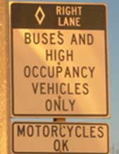
Figure 10-17 : Metered HOV Lane Sign
|
| 10.5 Design Considerations for Ramp Closures |
There are several design considerations to address when providing for ramp closures. Equipment, as well as signing and pavement markings, is required for ramp closures. As discussed in Chapter 5, there are three general types or classifications of ramp closures: permanent, temporary, and time-of-day. This section discusses the design considerations for each of these types of closures, provides some sample ramp closure layouts, and explains the various types of devices that can be used for ramp closures. |
| 10.5.1 Preliminary Design Considerations |
|
|
The decision to close a ramp permanently can be a very lengthy process. The many requirements include a detailed traffic analysis to show impacts associated with the closure; an extensive public outreach process to make sure that citizens are informed of the potential change and have an opportunity to provide input; and perhaps a temporary closure to observe and experience the actual impacts before a final decision is made. For example, in Seattle, Washington, for the I-5 Tukwila to Lucile HOV Lanes Project, the I-5 southbound Corgiat on-ramp was permanently closed. Extensive traffic analysis was required, and an open house was held to present the findings to the public and obtain their comments and concerns. The WSDOT Project Manager met with several community groups in the area and conducted a trial closure to evaluate the impacts. Since the impacts were not significant, the decision was made to permanently close the on-ramp.[19]
Temporary closures may be implemented due to construction activities, special events or weather-related events. Mitigation needed for a temporary closure is usually not as extensive as for a permanent closure, but the public outreach effort may be just as extensive. Although the disruption may only be temporary, it still has the potential to have severe impacts for users of the ramp. Ramp closures that occur only at times of low traffic demand like night-time hours will have less impact on travelers and may have less severe impacts overall, so the outreach effort will not need to be as extensive as for closures that affect peak traffic hours.
Construction impacts in work zones are also a design consideration for temporary closures. An example of a temporary ramp closure is the 6th Street ramp of I-64 in St. Louis, Missouri, which was closed for a two-year period.[20] This closure was brought about from a request to reconfigure 8th Street to accommodate a proposed stadium in the Central Business District (CBD). The Missouri DOT enlisted a consultant to perform numerous traffic studies, an access justification report for FHWA, and to coordinate with the St. Louis Cardinals baseball team.[21]
In addition to advance information for motorists who intend to use the ramp, information on the alternative route needs to be provided. Alternative route information may be posted on Changeable Message Signs (CMSs) on arterial streets near the ramp entrances. An example of a special event temporary closure is the Tacoma Dome in Washington State, which has required ramp closures in the past. During any major Dome event, Exit 133 (the exit nearest the Dome) used to back up onto the freeway. Since these queues were quite extensive and the ramp lacked the capacity to store the vehicles, this exit was closed using barricades and DMS to warn motorists. Information was also sent to the Dome patrons along with their tickets as a reminder of the freeway ramp closure. Closing the ramp during major special events was successful in eliminating queuing back to the mainline.
The Minnesota Department of Transportation (Mn/DOT) has been using gates since 1996 to prohibit freeway access during unsafe driving conditions such as severe snowstorms and major incidents. Gates on the mainline direct traffic off the Interstate and gates at entrance ramps prohibit access. Additional information about Mn/DOT’s program can be found in the Documentation and Assessment of Mn/DOT Gate Operations Report (October 1999).[22]
Like temporary closures, time-of-day closures also have the same design considerations with respect to traffic analysis, public outreach and trial closures, except that these types of closures are typically focused on the morning or afternoon peak periods. These types of closures can be used to help to facilitate mainline flow or reduce the occurrence of accidents. As an example, in Milwaukee, Wisconsin, I-43 southbound at State Street is closed daily from 2 to 6 PM. The reason for this recurring peak period closure was the high crash rates on the freeway at this location. The peak period closure was successful at improving safety in the area. The Wisconsin Department of Transportation (WisDOT) conducted a detailed accident analysis at this location because it has an extremely high crash rate (in the range of ten times higher than all other locations in southeastern Wisconsin). The analysis indicated that approximately 80 to 90 percent of the crashes were occurring during the afternoon peak period. The daily peak period closure began in the late 1980s/early 1990s. The ramp was equipped with a gate that automatically closed during the times of closure and opened immediately after. It should also be noted that this gate required extensive maintenance. The gate was often broken (by traffic determined to use the ramp anyway) and would again be broken within weeks of repair. This ramp will be closed permanently with the reconstruction of the Marquette Interchange.[23] |
| 10.5.2 Ramp Closure Layout |
|
|
There are various ways to provide a ramp closure, and the design or configuration depends on the type of closure and other factors. Figure 10-18 shows an example of how the Hawaii DOT used traffic cones to temporarily close the Lunalilo Street on-ramp and the Vineyard Boulevard off-ramp along the westbound H-1 freeway. More detailed information about this closure can be found in Chapter 11.
When construction occurs on or adjacent to a ramp, the construction may include single lane closures. Figure 10-19 shows a sample layout of a single ramp lane closure according to MUTCD standards.
Figure 10-18 : Lunalilo Ramp Closure Experiment Layout [24]
Figure 10-19 : Partial Exit Ramp Closure [7]
|
| 10.5.3 Ramp Closure Equipment |
|
|
There are a variety of design considerations in selecting the type of closure device, based on its application. A full ramp closure can be accomplished by using any of several types of barricades or barriers or completely removing the ramp. Some types of devices offer a more permanent type of closure, while others have the flexibility to allow the ramp to be opened at a later date or at other times. Each type of device varies with the level of maintenance required. And, of course, the installation process varies by device as well.
Barricades
Figure 10-20 and Figure 10-21 show barricades used by the Wisconsin DOT for ramp closure. The particular gate type used is dependent upon the part of the freeway where it is to be installed. As an example, Type III barricades are used at locations where closures are infrequent. They can be difficult and labor-intensive to use. Because of their design, an open, flat space is required for storing the posts. However, they are a low-cost installation with high visibility to motorists.
Semi-Permanent Barriers
A variety of types of semi-permanent barriers can be used for full ramp closures on a temporary basis, as done for special events or construction purposes. Examples of semi-permanent barriers include water-filled barrels or flexible pylons. Movable barriers are also an option and include barrels or wooden barricades.
The Long Island Expressway in New York utilizes mainline/ramp closures for construction at night. They have installed “drag net” devices (chain link fence with run-out cables) at the on-ramps to keep traffic off of the freeway mainline.[25]
Gates
Semi-permanent barriers can also be used for ramp closure. In some cases, automatic ramp gates can be used to close the ramp and prevent access to the facility. These gates can be controlled manually by staff or remotely from a Traffic Management Center (TMC) using 170 controllers (as done by WSDOT) or 2070 controllers (as done by Caltrans). This works well for peak-period ramp closures, special events or closures due to poor visibility (e.g., fog). As mentioned previously, automatic gates can require extensive maintenance depending on the motorists’ behavior. Gates that are frequently broken must be repaired in a timely manner.
As an example of a weather-dependent closure, the Tennessee DOT installed an automated gate system at ramp entrances to I-75 in conjunction with a fog warning system in 1992.[26] When the visibility decreases, the variable speed limit on the DMS is adjusted accordingly. If the visibility drops below a certain level (i.e., less than 73.2 meters (240 feet)), the on-ramps are closed on a 30.6-kilometer (19-mile) stretch of fog-prone freeway. The freeway has been closed due to fog, but also due to smoke from a nearby fire.[27]
Figure 10-22 is a sample gate closure detail that the Colorado Department of Transportation uses at ramp locations.
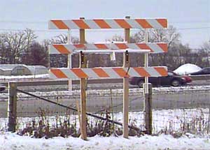
Figure 10-20 : Type III Barricade (Stored Position) [28]
Figure 10-21 : Type III Barricade (Deployed) [28]
Figure 10-22 : Sample Gate Closure Detail [29]
Figure 10-23 shows a traffic gate that the Wisconsin Department of Transportation uses for their ramp closures. The horizontal swing arms are used where closures are anticipated to be more frequent. Like the Type III barricade, they have high visibility to motorists but they require significant clear space to swing, are expensive to install, and need to have two large areas free of underground utilities for the footings. Vertical swing arms are easy to use and also have high visibility to motorists. However, they are difficult and expensive to install and are aesthetically unpleasant.

Figure 10-23 : Vertical Swing Arm Traffic Gate (Closed Position) []
Ramp Removal
Full removal is a more labor-intensive method and would require the demolition of the ramp and rehabilitation of the right-of-way with landscaping. This can be quite expensive, but allows for some redevelopment near the interchange. An example of this type of permanent ramp closure occurred in 2003 on the SR-91 Freeway in Orange County, California. Caltrans closed an underutilized interchange at Coal Canyon Road (in the Santa Ana Canyon). The interchange ramps have been removed and the right-of-way rehabilitated in order to provide a wildlife under crossing between the Cleveland National Forest to the south and the Santa Ana River to the north. Fences have been erected along either side of the freeway to guide the wildlife.[30] |
| 10.5.4 Signing and Pavement Markings |
|
|
Advance warning must be given to motorists to alert them of an upcoming ramp closure. This can take place in the form of electronic and print media, postings on the agency’s website, as well as signs and flags along the facility.
Signing and pavement markings may also be required at the ramp terminus. For example, if a left-turn lane on an arterial feeds into an on-ramp that is going to be closed, then the left-turn lane should also be closed to prevent access onto the ramp and the facility. The use of signs such as “Left Lane Closed Ahead” and pavement markings can be used to close such lanes. Figure 10-21 shows some examples of signing on the barrier devices at the ramp itself. With regard to pavement markings, for permanent or long-term closures continuing the yellow center line to close off the turn pocket or potentially hatching it may help to avoid confusion for the motorist. |
| 10.6 Design Considerations for Special-Use Ramps |
This section discusses design considerations for the various types of special-use ramps that were described in Chapter 6 - HOV/transit ramps and bypass lanes, construction ramps, emergency vehicle access ramps, and freight-only ramps. The following subsections provide additional detail on the types of equipment, signing and pavement markings that are required to implement these alternatives. |
| 10.6.1 Special-Use Ramp Layout |
|
|
One of the most common special-use ramp treatments is the HOV bypass lane, used in conjunction with ramp metering. This special-use treatment is described in detail in Section 10.4 and a typical layout is shown in Figure 10-2. Other special-use treatments that include a dedicated lane on a ramp should use a similar layout with appropriate signing and pavement marking to clearly indicate what types of vehicles are allowed to use the lane.
Another common special-use ramp treatment is an entire ramp dedicated to a specific type or class of vehicle. Common vehicle types that may have dedicated ramps include transit, HOV, emergency vehicles, or trucks (freight). Generally speaking, these ramps must meet all the standards of a general-purpose ramp. They should be designed to meet the acceleration and other characteristics of the vehicles they are intended to serve.
Freight-only ramps also conform to the concept discussed above. The ramp should be designed according to standard ramp design practices, with a truck as the design vehicle. An important design consideration for freight-only ramps is the distance of the merge and diverge points from the interchange, in order to avoid excessive grades to and from an elevated structure. |
|
HOV/Transit Ramps
HOV-only ramps (not HOV bypass lanes) as well as transit-only ramps do not require any special equipment beyond signing and pavement markings, which are discussed later in this section.
Construction Vehicle-Only Ramps
Barricades, barrels, or concrete barriers can be used to limit access on existing ramps that are temporarily designated for construction access only. Flexible pylons may also be used, but are not recommended due to heavy wear and tear they would experience during heavy construction use. Generally, a narrow gap in the barricades is left open with signing to depict that only construction vehicles are allowed to enter.
Emergency Vehicle and Maintenance Access Ramps
Emergency vehicle and maintenance access ramps do not require full design standards because they are not heavily used. Gates or other types of temporary blocking devices like flexible pylons may be used to prevent access of unauthorized vehicles. In some cases, surveillance is also used to monitor these access points.
For example, the I-90 floating bridge (between Seattle and Mercer Island) has special ramps on either side of the bridge dedicated for WSDOT maintenance vehicles and emergency vehicles. These ramps can provide direct access to the bridge during an incident. To avoid any confusion as to the intended users, these ramps are “camouflaged” to the motoring public by use of flexible pylons in one location and a movable barrier/gate in the other.
Emergency or maintenance vehicle access can also be provided similarly to construction vehicles. A small gap in the barricades can be left open with clear signing that only emergency vehicles or maintenance vehicles can enter.
If emergency and/or maintenance vehicles are also provided access to other special-purpose ramps (e.g., HOV or freight ramps), no equipment other than signing is generally required.
Freight-Only Ramps
Signing is used to designate ramps as freight-only ramps. In some cases, surveillance may be used to ensure that these special-use ramps are being utilized correctly. |
| 10.6.3 Signing and Pavement Markings |
|
|
HOV/Transit Ramps
HOV lanes are typically marked with diamonds every 152.4 meters (500 feet). The diamond size varies according to its application. For example, a diamond used for a freeway application would be larger than one used for an arterial or ramp application. This is directly related to the speed of the vehicles traveling on the given facility.
The HOV/transit ramp must be denoted with signing and pavement markings to indicate the allowable ramp users. Signs will designate the ramp as a “buses and carpool” lane or “transit only”. The sign should also indicate the HOV occupancy rate (2 or 3+ people). Where appropriate, the signs should also denote if motorcycles are allowed to use the HOV ramp. Figure 10-17 shows an example of an HOV/transit-only sign in Portland, Oregon on the HOV bypass lane. Signs should be placed so they are visible prior to entering the ramp, to prevent those who are restricted from using the ramp. The AASHTO Guide for the Design of HOV Facilities [7] and the MUTCD7 provide more detail on the signing needed for an HOV or transit ramp.
Construction Ramps
Construction ramps do not usually have traditional signing or pavement markings. By use of barrels or barricading equipment, it is usually apparent that the ramp is not intended for general motorists. Signs may be installed that display the words “Construction Entrance” or similar wording.
Emergency Vehicle and Maintenance Access Ramps
Since many emergency vehicle or maintenance vehicle access ramps are actually “hidden” from the public view, signing and pavement markings may not be necessary. A “Do Not Enter” or “Authorized Vehicles Only” sign may be used as regulatory signs to designate the restricted use of the ramp at the point of restriction. The pavement markings may consist of hatching the lane to alert motorists of the restricted access.
Freight-Only Ramps
Freight-only ramps require advance warning signing to indicate the specific use of the ramp. Typically, no special pavement markings are required. |
| 10.7 Design Considerations for Terminal Treatments |
Ramp terminal treatments consist of signal timing and phasing adjustments, ramp widening, and adding or extending turning movements and storage lanes. Terminal treatments are implemented along the arterial street network at the ramp location or on the ramps near the intersection with the arterial. Many different alternatives are possible. One key consideration in the design of terminal treatments is to maintain good flow on the arterial and manage the queues that may result from a traffic signal or ramp meter. The MUTCD7 and AASHTO6 guidelines offer information on various design considerations for any ramp or arterial intersection. Each agency may also have its own design manual and guidelines to follow.
Signal timing can be modified in various ways. At entrance ramps, the timing should be adjusted such that the traffic does not block the intersection when queues form from the ramp meter. At exit ramps, care should be taken to ensure that queues do not form and back up onto the freeway facility. As discussed in Section 6.6.3, the agencies operating ramp meters should coordinate the meter timing with the signal timing on arterials in order to optimize intersection flow.
Ramp widening may need to occur if the existing storage capacity of the ramp is deemed insufficient or if an HOV bypass lane is to be provided. There must be sufficient right-of-way to accommodate widening, otherwise use of the shoulder may be investigated. Sufficient space for maintenance personnel and their vehicles also needs to be a design consideration when widening ramps.
Access to the HOV bypass lane can be an issue when there is a dual left-turn lane onto the ramp. Weaving and safety issues may arise if the vehicles must merge into one lane a short distance after two lanes of traffic turn left. This may be a case where advance signing can help direct motorists to the proper lane to avoid or minimize last-minute merging or lane changing. |
| 10.7.1 Terminal Treatment Layouts |
|
|
Most ramp terminal treatments require no changes to ramp or arterial geometrics. If a storage lane is needed, the agency should refer to their design manual for guidance. Some ramp terminal treatments will require new pavement markings or new signing. These situations are covered in section 10.7.3. |
|
Many of the terminal treatment alternatives do not require implementing specific pieces of equipment. Much of their application involves signing or pavement markings. For example, ramp widening would involve restriping the ramp to add a lane, either with or without adding additional pavement. Channelization can involve adding a new turn lane or extending the storage lane onto the arterial street or further upstream on an exit ramp. Signal timing modifications are made at the controller or from a central traffic control system, but no additional equipment is required. With turn restrictions, there can be permanent or time-of-day solutions. The signing and pavement marking requirements are discussed in the following subsection. |
| 10.7.3 Signing and Pavement Markings |
|
|
If turning movement restrictions are to be imposed, signing is required to inform motorists. Figure 10-24 and Figure 10-25 are two example signs that may be used. These regulatory signs are placed on the local streets with concurrence from the local agency, or on the exit ramp approaching the ramp terminal intersection. In some cases, the hours or days of restriction may be added if the turn restriction occurs only during a peak period or specific time of day. The signing can also consist of other information, such as whether the ramp meter is turned on or off or the state of the freeway congestion.
Figure 10-24 : Right Turn on Red Restriction Sign [7]

Figure 10-25 : Left-Turn Restriction Sign [7]
Pavement marking generally consist of striping either solid or skip lines, depending on the application, and pavement arrows to reinforce the messages on signs. For example, if different lane utilization is required at an exit ramp intersection, signs should be placed overhead or on the shoulder to inform the driver of the movements allowed from each lane. Pavement arrows generally will reinforce the signs. If a lane is a right-turn only lane, then a sign should designate the turning requirement and a right-turn arrow should be placed on the pavement.
Specifics of signing and pavement marking can be found in the agency’s design manual or in the MUTCD. [8] |
| 10.8 Planning and High-Level Design for ITS Technology and electronic Infrastructure |
ITS elements are typically required when implementing many of the ramp control strategies. For ramp closure systems, ITS elements include gate controls, monitoring/surveillance, and electronic signage for driver information. Ramp metering includes extensive field devices (e.g., signals, detection, advanced warning signs), communications, and control software (including controlled firmware and central software). ITS planning follows a systems engineering process, whereby agency staff can guide their ITS projects to success by taking their solutions step-by-step from concept through implementation, operations, and assessment.[32] This process is covered in greater detail in the FHWA Freeway Management and Operations Handbook [11] and the National Highway Institute’s course “Introduction to Systems Engineering”. The key steps are outlined below.
Concept of Operations – The Concept of Operation (Con Ops) includes the vision, goals, and objectives for the strategy to be implemented. It should include detailed information on how the operating agency wishes to operate the system. The Con Ops should be based on a set of clearly defined user needs.
High-Level and Detailed Requirements – Requirements are derived from the Con Ops and the user needs it identifies. These include functional and technical requirements. The system being implemented and the required interfaces need to be outlined. A systems architecture will help illustrate the systems and define the interfaces.
Various technology options exist for the components of the ramp management strategies. Each should be assess for cost, maintenance, and operational capabilities. These components may include central computer systems, field controllers, gate systems, dynamic message signs, detection, or surveillance.
High-Level and Detailed Design – High-level designs begin to translate the requirements into system components. Detailed design furthers this process to a point that the system can be developed and implemented so that it will meet the requirements established earlier. A traceability matrix should be developed to illustrate which design elements address specific requirements.
Implementation – This segment of the process outlines the overall plan for the ITS system. It identifies project cost and schedule as well as integration with existing components or capabilities.11 Implementation actually “builds” and installs the system and its components.
Integration and Testing – Integration and testing puts the components of the system together and tests to make sure the components meet the requirements that apply.
System Acceptance – This step ensures that all of the criteria set forth in the requirements phase have been met in the final system.
Operations and Maintenance – This step includes putting the system to work to fulfill its intended functions. During the operations and maintenance phase, agencies should verify the life cycle costs of the system including training, operations and maintenance. The operating agency should also identify how to upgrade or enhance the system in the future. For many ramp management strategies, this involves getting the maintenance staff on-board during the planning stages, to ensure that they will be able to effectively maintain any new ITS devices. |
| References |
1. US Department of Transportation, Federal Highway Administration. Environmental Impact Statement (EIS) Documentation. Available: http://environment.fhwa.dot.gov/projdev/docueis.htm
2. Parsons Brinckerhoff – Angela Findley, Environmental Manager. NEPA Process. April 18, 2005 discussion.
3. Sound Transit. Sound Transit Motion No. M20001-20. Available: http://www.soundtransit.org/about/board/motions/html/MotionM2001-20.html.
4. Versar, Inc. Environmental Compliance, National Environmental Policy Act, Versar’s Approach to the NEPA. Available: http://www.esm.versar.com/esm/eis.htm
5. US Department of Transportation, Federal Highway Administration Website. An Overview of Transportation and Environmental Justice. Publication No. FHWA-EP-00-013. https://www.fhwa.dot.gov/environment/ej2000.htm
6. American Association of State Highway and Transportation Officials. AASHTO Green Book: A Policy on Geometric Design of Highways and Streets. Fifth Edition. 2004.
7. US Department of Transportation, Federal Highway Administration. Manual on Uniform Traffic Control Devices for Streets and Highways. 2003 Edition. Available: http://mutcd.fhwa.dot.gov/pdfs/2003/pdf-index.htm.
8. Caltrans Traffic Operations Program in cooperation with Design and Local Programs and the Department of California Highway Patrol. Ramp Meter Design Manual. January 2000.
9. Piotrowicz, Gary and James Robinson. Ramp Metering Status in North America, 1995 Update. Final Report. June 1995.
10. Transportation Research Board, National Cooperative Highway Research Program. HOV Systems Manual. Report 414, National Academy Press, Washington, D.C. 1998.
11. FHWA, U.S. Department of Transportation. Freeway Management and Operations Handbook. Publication FHWA-OP-04-003. September 2003. Available: http://ops.fhwa.dot.gov/freewaymgmt/freeway_mgmt_handbook/index.htm
12. PB Farradyne. ITS Program Management Tools and Processes, Recommendations for FDOT District 6. 2002.
13. Washington State Department of Transportation. Design Manual, Traffic Interchanges, Section 940. May 2000.
14. Washington State Department of Transportation. High Occupancy Vehicle Facilities Design Manual, M 22-01, Chapter 1050. January 2005.
15. Caltrans Traffic Operations Program in cooperation with Design and Local Programs and the Department of California Highway Patrol. Ramp Meter Design Manual. January 2000.
16. Jacobson, Eldon L., and Jackie Landsman. Case Studies of Freeway-to-Freeway Ramp and Mainline Metering in the U.S., and Suggested Policies for Washington State. October 1994.
17. Caltrans, Materials Engineering and Testing Services. 2070 Controller – Introduction to the Controller. Available: http://www.dot.ca.gov/hq/esc/ttsb/electrical/pdf%20files/Into%20to%202070.pdf
18. Letter to Mr. Keith Golden, Georgia Department of Transportation from Ms. Regina McElroy, Office of Transportation. Reference HOTO-1. September 30, 2005.
19. Parsons Brinckerhoff - Stan Ching. April 2, 2004 email.
20. Parsons Brinckerhoff - Dan DeArmond. April 5, 2004 email
21. Parsons Brinckerhoff, “I-64 at 6th Street Access Justification Report”, January 2003.
22. BRW, Inc. Documentation and Assessment of Mn/DOT Gate Operations Report. October 1999. Available: http://www.dot.state.mn.us/guidestar/pdf/gatereport.pdf
23. Wisconsin Department of Transportation - Nancy Huisman. June 14, 2004 email.
24. Prevedouros, Panos D. H-1 Freeway Ramp Closure: Simulation and Real-world Experiment. July 24, 1998.
25. Parsons Brinckerhoff - Steve Fleming. April 5, 2004 email.
26. PB Farradyne - Cary Vick. April 1, 2004 email.
27. Mitretek Systems. Best Practices for Road Weather Management, version 2.0. 2003.
28. Wisconsin Department of Transportation. ITS Design Manual, Chapter 10 – Traffic Gates. December 2000.
29. Colorado Department of Transportation. Standard Plan M-607-15, Road Closure Gate Drop Detail.
30. Parsons Brinckerhoff - Darren Henderson. ,April 2, 2004 email.
31. American Association of State Highway and Transportation Officials. Guide for High Occupancy Vehicle (HOV) Facilities. Ballot Draft. January 2004.
32. Professional Capacity Building Program and the ITS Joint Program Office. The ITS Systems Engineering Series, A Subset of the ITS Curriculum. Available: http://www.pcb.its.dot.gov/brochures/ITS_SE.htm#toc2
Continue to Chapter 11 |
|
|