
Freeway Management and Operations Handbook
Chapter 14 – Transportation
Management Centers
Page 2 of 5
14.2.8 Other Information Displays
In addition to workstations and the associated user interface, other methods may be used to display information to operators in a TMC, including video monitors, individual large-screen displays, and video walls. A dominant feature in nearly every TMC is an information display board or screen. These display walls are used to provide a broad overview of the status of the system (e.g., traffic flow conditions on roadways, status of equipment, locations of vehicles, video images) to operators, managers, and visitors in the TMC. They are typically used to display graphic information and video. Two different kinds of information displays are generally used in TMCs – individual large screens and video walls.
14.2.8.1 Individual Large Screen
These display walls are comprised of a single or multiple screens, ranging in size from approximately 45" to 120" in diagonal. The difference between this type of display wall and a video wall is that a screen is large enough to display a suitable amount of information legibly to persons in the TMC. Besides showing status information on computer-generated maps, operators can also display live video from CCTV cameras and television images on the screen. Because the images are usually generated by computer, the operator can zoom to various levels of detail on the display. The primary disadvantage of projection television, however, is that the resolution can sometimes make the image become blurry. Furthermore, because of its sensitive optics, it frequently requires realignment and adjustments. Figure 14-6 shows an example of a TMC with a projection television map display.
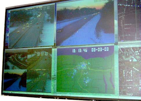
Figure 14-6: Projection Television Display Wall in
a TMC
(Source: NYS Department of Transportation & Monroe County Department of Transportation)
14.2.8.2 Video Walls
Video walls are used in most new freeway management TMCs. A video wall is a matrix of television monitors used as a single display. Each individual monitor can be used to display a single image or can be used to compose part of a larger display. In effect, it allows the display wall to be widowed or tiled much like a personal computer. By using a video wall, the operators in the TMC have the flexibility of customizing the presentation of the information as conditions warrant. Figure 14-7 shows an example of a TMC with a video display wall.
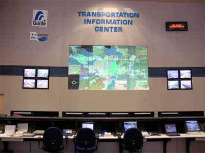
Figure 14-7: Video Display Wall in a TMC (Source: Missouri DOT)
14.2.8.3 Design Guidelines and Recommendations
The following guidelines and recommendations are provided to help in designing visual displays in TMCs:
- Avoid too much detail on large maps or status boards.
- Limit the number of colors for maps, target symbols, alphanumeric headings, etc.
- If moving objects are displayed on a map, keep the number at a minimum and display only those that move slowly.
- If color-coded object information is to be used on a large map display, use only a neutral color, such as gray, for the map background; this allows the color targets to have maximum effect (contrast).
- When front projectors are to be used to project information on a large map display, ensure that the projectors are positioned so that they are not readily visible (i.e., causing obstructions and glare) to the operating personnel.
- Determine and provide the properly sized alphanumeric characters and/or symbols on the large-screen displays for the maximum viewing distances at which each set of characters and symbols must be read.
- Use unambiguous coding techniques to help operators in discriminating between old and new data. Color codes should agree with commonly accepted practices.
- Orient maps with north to the top.
14.2.9 Automation
The role of the operator in a system can be defined in terms of whether a human or a machine makes the decisions (i.e., closes the loop) in a task or process. The role of the operator in the decision-making process can be placed into four categories:
- Direct performer – the operator performs all the functions of the system.
- Manual controller – the machine components are heavily involved in the decision-making process as sensors and effectors, but the actual loop-closing aspect of the function is solely the responsibility of the human.
- Supervisory controller – a machine component is allowed to close the loop under supervision of a human operator who may intervene and adjust or override the machine's decision.
- Executive controller – the machine is totally responsible for performing all functions of the system; the operator is only there to keep the machine operating.
The acceptable level of automation varies from site to site. In some locations, the long-term system goal is to be fully automated while, at other locations, the goal is for the operator to continue to be a critical element in the operation of the system. Each philosophy has significant implications with regard to the overall design of the TMC, the workstations and the user interface.
A continuum of operator roles exists that defines how much automation is needed to accomplish a function. At one end of the continuum, a function is allocated solely to the human, and at the other end, solely to the machine. In between, performance of the function is shared by human and machine components. As shown in Figure 14-8, the continuum can be divided into four major regions; each region defines a generic operator role in relation to automation. Because it is a continuum, how much automation occurs varies within each region.
Figure 14-8: Machine and Human Sharing of Functions D
How much automation is acceptable in a TMC varies from center to center, depending upon the experience of the operators, the operational goals and philosophy of the agency, and the sophistication of the system. In many locations, routine functions in the TMC can be automated. For example, different TMCs use different methods for generating messages for display on changeable message signs, including the following:
- Messages are entered manually.
- Messages are entered manually with computer assent.
- The operator chooses from selection of canned messages.
- The computer determines a response plan with the assistance of an operator, with the operator implementing the plan.
- The computer determines a response plan and implements the plan with no operator intervention.
Automation systems should be designed to help and support the operators. Operators should be fully aware of what information the system software has, what the automated systems is doing, why it is doing it, and what it is going to do next. At a minimum, the operator should be able to switch off the automated system to prevent future problems or to correct improper decisions. If automated systems are to be used, the level of automation should be gradually increased throughout implementation. Initially, an operator should be present in the control room to review and approve all automated system actions. A detailed log of automation failures should be kept. As failures are eliminated, the role of the operator in the decision-making process can be reduced.
14.2.10 Communications Systems
In general, system designers need to be concerned with four types of communications systems when designing a freeway management system:
- Communications system that links the field devices with the TMC and permits the transfer of data and commands. Data communications can generally be transferred with slow-speed, low-capacity media, which video generally requires high-speed, high-capacity media. (This is discussed in Chapter 17)
- Communications system that links the computer systems inside the TMC, which are responsible for processing information and commands, generating displays and reports, and interfacing with the TMC operators. Most freeway management systems in operation today use local area networks (LANs) to connect their computer and display equipment in the TMC.
- Communications system that permits operators in the TMC to converse with other personnel (and also the public) by voice.
- Communications system that links the systems inside the center with other centers (other traffic management centers, transit centers, emergency services centers, etc.) or the media. (This is discussed in Chapters 16 and 17)
14.2.10.1 Local Area Networks
The term Local Area Network (LAN) is commonly used to describe the type of communications system that links the digital computers internal to the TMC. By definition, an LAN is any telecommunications system that serves a limited geographic area (typically a single building or campus). The term "network" refers to the fact that multiple users are interconnected.
No single LAN design is ideal for use in a TMC. The design of the LAN needs to support the functions and the types of data exchanges in the TMC. The simplest type of LAN permits the exchange of information between computers and computer-like devices (such as word processors, operator workstations, database managers, etc.). More complex forms of LANs are required to support the transmission of video and audio information besides data.
While the complexity of the LAN varies depending on the type of data being transmitted, every LAN has the following basic components:
- User workstations (as discussed in a previous section of this chapter). In TMC applications, workstations may consist of conventional PC computers, intelligent workstations, or terminals.
- Supporting processing equipment. Supporting processors,
known as servers, are connected to the LAN to execute functions that
cannot be provided by individual workstations. Generally, servers are
used for the following applications:
- Execute large computer programs that exceed workstation capacities.
- Provide centralized data storage and retrieval functions (file servers).
- Interface with external communication facilities (communications servers).
- Interface with peripheral devices.
The capacity of the supporting processors can vary from that of a personal computer to that of a microcomputer computer.
- Peripheral devices. In most TMCs, a variety of peripheral
devices are supported on the LAN, including the following:
- Printers
- Modems
- Plotters
- Optical character readers
- Telex
- Scanners
- Fax machines
In some systems, the LAN is also used to support video and voice transmissions via connections to television equipment and the telephone system. In larger LANs, a special processor, known as the network control station, is often used to monitor the communications traffic on the LAN continuously, and to accumulate statistics on workstation usage, transmission quality, and network configuration.
When planning a LAN system, the first consideration should be the selection of the type of system or topology that is most appropriate for the application requirements. Generally, three types of topology (i.e., physical shape) are commonly used in designing LANs: a star topology, a bus topology, and a ring topology. Figure 14-9 illustrates each of these topologies. Advantages and disadvantages of each topology are summarized in Table 14-2.
Figure 14-9: Examples of Common LAN Topologies D
| Topology Type | Attributes | Advantages | Disadvantages |
|---|---|---|---|
|
|
|
|
|
|
|
|
|
|
|
|
Connections between LAN nodes can be established over twisted-pair cable, thin coaxial cable, standard coaxial cable, or optical fiber. Each of these alternatives has increasing capacities. Twisted-pair (telephone) cable is smaller and cheaper than other communications media, but is subject to electrical and radio interference. Coaxial can carry higher frequencies and data rates than twisted-pair but is more difficult to manipulate physically. Optical fiber is popular because of its small cable diameter, protection against electromagnetic or radio interference, low attenuation, and large bandwidth, but is generally more expensive to install than the other media. Factors that influence the selection and implementation of communications media used in the LAN include the following:
- The amount of data being transferred between devices (i.e., capacity levels).
- The potential for external interference.
- The physical distance between devices.
- The need for future expansion.
The ability to diagnose and predict its own failure is an important factor in designing an LAN. Simple layouts and well-established procedures should facilitate quick repair. In addition, system planners should anticipate expansion needs in the design of the system. The internal design of the building should incorporate adequate routing ducts and conduits to hold all future growth needs. In addition, access rooms should be provided to ease the job of adding and maintaining an LAN.
14.2.10.2 Voice Communications
Systems within the TMC are also needed that allow operators to talk with individuals outside the TMC. The types of voice communication systems needed within a TMC depend primarily upon the functions to be performed by the system, existing communications systems, local availability, and agency preference. Voice communications are commonly used in TMCs for the following purposes:
- Communications with incident response teams and emergency responders including fire, police, emergency medical service providers, hazardous material teams, etc.
- Communications with operations and maintenance field personnel.
- Communications with operations and dispatch staff in other centers or from outside agencies.
- Communications with motorist call boxes.
- Transmission of dispatch information, data, and calls.
- Communications with management and administrative staff, both internally and with outside agencies.
Common types of voice communications systems included in the TMCs include intercom, direct line telephone connects, switching telephone systems, radio, and cellular telephones.
14.2.11 Software Architectures
Software applications – residing on servers, workstations, and field device processors – provide the functionality (including the user interface) for a freeway management system. Software application architectures have evolved over the years, progressing from mainframe (host based) character cell terminal applications to some form of networked PC computing to some form of client server based application architecture. Throughout this evolution, many terms were invented to describe these architectures, often with multiple or confusing meanings. For the purpose of this section, the definitions are provided in Table 14-3.
| Term | Definition |
|---|---|
| Client / Server: | The off loading of database query analysis and other compute intensive functions from the client (user interface) computer to the server computer. |
| Internet: | (capital I) Worldwide network (of networks) primarily used for the sharing of information between two or more parties. Information distribution technologies. |
| internet / intranet: | (lowercase i) Network or network of networks not directly connected to the Internet or protected from the Internet by combinations of hardware and software, but utilizing communication protocols identical to those used on the Internet. |
| Networked PC computing: | A graphical user interface implemented at the end-user's desktop (primarily Microsoft Windows) where some or all of the computing, formally performed on the mainframe (host) is done in part or completely on the user's desktop computer. Ushered in the advent of powerful graphical user interface applications. |
| Thick Client: | Server based computing solutions where some of the "work" is moved from the desktop back to a centralized server while preserving the benefits provided by the powerful graphical desktop environments. |
| Thin Client: | A network dependent Web browser based user interface, responsible for gathering user input and the display of the application's results. Applications run on the server, not on the client (desktop). A PC, or a network computer can support this form of thin client. |
| Web Browser: | Software used to display text and graphic information encoded using protocols based on Internet standards. |
At the time of writing this Handbook, many system implementations have utilized a large distributed client-server / thin client / internet protocol based architecture, based on the technologies of the Internet. This approach has both advantages and disadvantages:
- Web browsers and environments supporting web browsers are multi-platform, allowing for the selection of hardware and software from many different providers. Because the technology is the technology of the Internet, companies both large and small continue to improve what is available, making it unlikely that the solution will become an unsupported technological dead end.
- Using a generic user interface device with a stable local configuration reduces downtime due to device failure. When a user interface device fails, it is easily swapped out and replaced because there is little or no customization in the environment. This differs from the PC environment where a user generally configures and expands what the device is used for, often requiring time consuming reconfiguration.
- When the server is down, all clients are affected (In this architecture, all of the work is done on the server, and a loss of the server prevents all clients from doing work.) This disadvantage can be addressed with redundant equipment supporting the server.
- Some ITS functions and applications may require performance in some areas that cannot be met using only HTML – for example, a full-featured GIS based display. Displaying equipment status change updates on a map by re-loading the entire map image will be slow (and possibly unusable by an operator) and wastes network bandwidth. Several approaches can address this issue. One is to build customized "plug-ins" to handle the display of specialized graphic display items; although this requires that a version of the plug-in be created (written) for each operating system platform supported. Alternatively, small programs can be written in the JAVA language and sent to the browser when they are needed. This approach work across platforms, but may not reach the display performance of a thick client GIS system.
- Unlike the thick client approach – where application access by users is through a piece of complex customized software residing on a computer of its own – anyone with a browser who is connected to the network potentially has access to the functions of the system. Thus, it is relatively easy to distribute any portion of the information contained in the system to users outside of the network, either within or outside of the organization. This is because the underlying environment is ubiquitous and almost all consumers of the information have the necessary components to access the system. Depending on what portion of the system is to be exposed to users outside of the core users, software in the server can be configured to accommodate almost any security scheme (to prevent unauthorized users from gaining access to the system.) Moreover, the thin client application architecture can yield a system where a center-to-center user interface is straightforward to implement and support. This can be accomplished by allowing users in one facility access to the systems at another facility simply by having them reference a user interface on the other facility through their web browser.
14.2.12 Security
Security surrounding TMCs largely depends on the nature of the center and its objectives. Because of the vast differences in the purposes and capabilities of these centers, the appropriate levels of security to protect them vary widely, as do the perceptions of security risk. Many original freeway management TMCs around the country were developed strictly as a traffic control measure and, as such, their operators did not see any particular threats to the facility. This stemmed from a perception that there would be little intrinsic value in attempting to attack or otherwise break into such a facility. In contrast, many facilities currently being brought on-line incorporate police, transit, emergency management, and traffic operations. These facilities are perceived to represent a much more likely target for computer hackers, theft of data, and, given the events of 9-11, potential terrorist activities.
Several generic security measures can be taken to limit physical access to facilities. Effective security is an interplay of three elements: natural and architectural barriers, including anything from landscaping strategies that discourage access, to the number, location, size, and type of doors and windows; human security, including the protection provided by guards and other personnel; and electronic security, provided by any one of the array of systems now available.
Obviously, location of the facility will play a central role in determining what security measures are appropriate. Here again, the needs of staff should be considered in selecting what countermeasures are employed. Communication systems, power supplies, access points, physical integrity of the building, and several other issues are all directly affected by security considerations. In addition, what countermeasures can be used is affected by building codes regarding access and egress during emergencies such as fires. Yet another layer of regulatory codes is associated with the Americans with Disabilities Act, which can affect aspects ranging from physical security barriers to systems that must accommodate both the blind and deaf. Security systems also must be designed so that they are not too obtrusive, intrusive, or otherwise intimidating to employees (Note: Additional information on infrastructure security, including TMCs, is provided in Chapter 12).
Computers in the TMC are also a source of security concern for many operating agencies. According to one source, the majority of all computer security losses have been attributed to errors or omissions. Major sources of other computer security losses include dishonest and disgruntled employees, and external threats such as disasters. Only a small percentage of security losses were credited to outside sources, such as hackers. Nevertheless, because of the publicity surrounding hackers and viruses, an undue amount of attention is often focused on protecting against external threats. The extent of the risk to computer systems will vary greatly from agency to agency. Risks include those against the data network and the data itself. The determination of how much security is necessary reverts to the need for risk assessment. Multiple layers of firewalls and other security measures may be warranted in some systems. Several publications are available that offer further detailed exploration of computer security measures that can be implemented.
14.2.13 Data Archiving
As discussed in Chapter 4, in order to monitor the long-term performance of the transportation network, the real time operations data collected by a freeway management system (FMS) must be systematically retained and reused – a process known as "data archiving" or data warehousing. It is commonly the TMC – which collects large amounts of data for use in real-time traffic management – where this data are archived for some future use.
ITS data archiving is defined as the systematic retention and re-use of transportation data that is typically collected to fulfill real-time transportation operation and management needs. It is also known as data warehousing or operations data archiving. Transportation operations and their respective sensors and detectors are a potentially rich and detailed source of data about freeway system performance and characteristics. Table 14-4 inventories data items that can potentially be collected by freeway management system applications and operations groups
| ITS Data Source | Primary Data Elements | Real-time Uses | Possible Multiple Uses of FMS-Generated Data |
|---|---|---|---|
| Freeway traffic flow surveillance data |
|
|
|
| Visual and video surveillance data |
|
|
|
| TMC-generated |
|
|
|
| Traffic flow metrics |
|
|
|
14.2.14 Emerging Trends
Much has happened in the development and operation of TMCs over recent years; and like most technology-based endeavors, such changes and advancements can be expected in the future. Some of the emerging trends are not necessarily new, but are the result of technologies becoming more mature, and therefore, more commonplace. Not all of these trends are technical in nature; some are institutional. Those emerging trends include:
- Automation of system functions is becoming more common today as advanced computing techniques and control theory, such as neural networks and fuzzy logic, become more understood in our industry. The use of knowledge-based "expert systems" to assist operators with decision making is another example
- Emerging standards, such as the National Transportation Communications for ITS Protocol (NTCIP), for communication between centers, and between TMC and field devices.
- Use of call center technology and computerized telephony for both call center functions (receiving calls from motorists) and distributing information to travelers (e.g., highway advisory telephone or 511 systems).
- Since the horrific events of 9/11, there is an emphasis throughout the country on assessing means to protect the physical roadway infrastructure, particularly bridges and tunnels that are potential targets. The TMC will most likely become the monitoring point where operators will respond to alarms of stopped vehicles on bridges or in tunnels. Moreover, the TMC may be considered a critical asset itself, thereby affecting the design of the facility and its access, as well as operational procedures.
- As previously discussed, the TMC is becoming a data mart / warehouse, where large amounts of data are gathered, archived, and stored for non-real-time uses such as evaluation and planning purposes.
TMCs are becoming coordination and communication hubs for maintenance activities. For example, the using the TMC to house maintenance managers and dispatchers during snow emergencies, when the emphasis is not necessarily on moving congested traffic, but on monitoring the roadway's physical condition in order to direct snow removal. Utilizing Roadway Weather Information Systems (RWIS) data brought into the TMC and monitoring weather forecasts, maintenance managers and dispatchers at the TMC have real-time information on roadway ice & snow conditions in order to manage the snow removal team.
A similar example is that of maintenance management systems linking the traffic management system with the maintenance work order development process within an agency to automatically issue maintenance work orders on field equipment. As noted in Reference 8 ("Freeway Management and Operations; State of the Practice"), the "state-of-the-art in management systems incorporates managing systems operations and system assets with managing maintenance activities. State-of-the-art management systems often utilize inter-agency archive data systems to store and retrieve information pertaining to the management activities. Examples of management systems include:
- Incorporating freeway management assets in asset management systems. Asset management is an emerging concept for public agencies. Asset management is geared toward optimizing resource allocation across transportation assets that are very broadly defined. It is generally viewed to provide improved decision making for investments in new capacity, improvements, preservation, and operations. Information is needed on a broad array of assets, but is usually focused on the roadway, structures, guardrail and barrier, signs, and other traditional roadway features. Asset management allows agencies to track the condition of their current system and the adequacy of their annual expenditures. Asset management systems are not specifically designed for electronic systems, but electronics can be entered into the system and tracked.
- Establishing network management systems for fiber optic and other telecommunication systems. Just as a system is needed to manage the maintenance of freeway management system components, a system is needed to manage the maintenance of the telecommunications network. These systems identify the devices that are attached to the telecommunication system, track the individual strands of fiber or pairs of twisted pair cable that are used by devices, and identify the specific telecommunications equipment included in the system.
- Utilizing configuration management systems to help freeway system managers locate and identify the current versions of software, documents, procedures and models of hardware and firmware in use in their system. These systems are focused on tracking components and documentation that are part of a central system, both those in the central location and those in remote locations. The systems track replacement and upgrades of equipment and the software resident in the equipment. The idea behind these systems is to know what may have changed if a systemic problem is uncovered. Very often, systems used to manage telecommunication networks are used for hardware configuration management. In fact, freeway management telecommunication systems should be included in the overall configuration management system. The network management systems mentioned above can facilitate this inclusion. System configuration management is a relatively new concept in transportation and is an outgrowth of the emphasis on software configuration management. (Note: Configuration Management is discussed in Section 14.3.)"