
Freeway Management and Operations Handbook
Chapter 14 – Transportation
Management Centers
Page 1 of 5
14.1 Introduction
Freeway management is performed through a combination of human (i.e., institutional), and physical (i.e., technical) elements. The human elements are the managers and operators who plan and perform control functions, while the technical elements are those tools, typically ITS, that assist the operators in performing their functions. These two elements are brought together at the transportation management center (TMC). The TMC is the hub or nerve center of most freeway management systems. (Figure 14-1) It is here data about the freeway system is collected and processed, fused with other operational and control data, synthesized to produce "information", and distributed to stakeholders such as the media, other agencies, and the traveling public. The information is used by TMC staff to monitor the operation of the freeway and to initiate control strategies that affect changes in the operation of the freeway network. It is also where agencies can coordinate their responses to traffic situations and incidents.
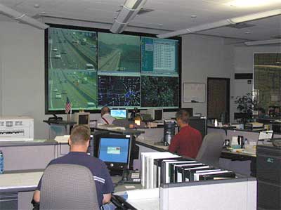
Figure 14-1: Transportation Management Center
The role of a TMC often goes beyond the freeway network and the particular responsible agency, functioning as the key technical and institutional hub to bring together the various jurisdictions, modal interests, and service providers to focus on the common goal of optimizing the performance of the entire surface transportation system. Because of its critical role in the successful operation of a freeway management system (and perhaps the broader surface transportation network), it is essential that the TMC be planned for, designed, commissioned and maintained to allow operators and other practitioners to control and manage the functional elements of the freeway management system, and possibly beyond.
14.1.1 Purpose of Chapter
This Chapter is a tool for freeway management practitioners of all levels involved with the planning, design, commissioning, operations and maintenance of a TMC. It is not intended to be an all-encompassing, "Everything You Ever Wanted To Know About TMCs..." desk reference, but instead, an overview of TMC's from planning to on-going management, including:
- The elements of a TMC,
- Its role in freeway management,
- Processes for planning, designing, commissioning and managing a TMC (and related ITS elements)
Several excellent references are available regarding the planning, design, implementation, and operation of TMCs. Many of these are referenced herein, including the following Internet sites:
- ITE TMC Committee (http://www.ite.org/tmc/index.htm). This web site is intended to serve as the "one-stop location, providing a forum to access and facilitate the electronic exchange of information among practitioners interested in TMCs." (Reference 1)
- The TMC Pooled Fund Study (PFS) (http://tmcpfs.ops.fhwa.dot.gov). The goal of the TMC PFS is to assemble regional, state, and local transportation management agencies and FHWA "to identify human centered and operational issues that are common among TMC operators and managers; suggest approaches to addressing identified issues; initiate and monitor projects intended to address identified issues; disseminate results; and assist in solution deployment." (Reference 2).
Each of these web sites provides information on resources, best practices, and TMC-related studies.
14.1.2 Relation to Other Freeway Management Activities
The TMC serves as a focal point of control and management of infrastructure and procedural functions. Accordingly, there are many freeway management activities that relate directly to TMCs; and to understand the role of TMC's within the freeway management spectrum, it is important to understand the relationships between these activities and the TMC. Table 14-1 itemizes those related activities and their relationship.
| Ramp Management and Control (Chapter 7) | The data collected from detection and surveillance components in the field is synthesized at the TMC, and systems and operators in the TMC monitor and manage the ramp management systems. Central software within the TMC often communicates with and controls the operation of the ramp controllers in the field. |
| Lane Management and Control (Chapter 8) | The data collected from detection and surveillance components in the field is synthesized at the TMC, and systems and operators in the TMC monitor and manage the lane management systems. |
| HOV Systems (Chapter 9) | For HOV systems using automated gates, overhead lane control signals or dynamic message signs (DMS), these central systems are typically located and maintained at the TMC and the monitored and managed by TMC software and operators. |
| Traffic Incident Management (Chapter 10) | The TMC is the nerve center for transportation agency management of traffic incidents. In some multi-agency centers that include emergency management dispatch, the TMC can act as the situation or war room for multi-agency response and coordination. |
| Planned Special Event Management and Control (Chapter 11) | The TMC is the nerve center for the transportation agency management of planned special events. In some multi-agency centers that include emergency management dispatch, the TMC can act as the situation or war room for multi-agency response and coordination. |
| Emergency & Evacuation Management (Chapter 12) | The TMC is the nerve center for the transportation agency management of emergency and evacuation events. In some multi-agency centers that include emergency management dispatch, the TMC can act as the situation or war room for multi-agency response and coordination. |
| Information Dissemination (Chapter 13) | Information dissemination is one of the primary roles of a TMC. The TMC is the gathering place for real time information and planned special event information, and it is from the TMC that the information, created from fused and synthesized data, is distributed to stakeholders via roadside infrastructure (DMS and Highway Advisory Radio). TMCs also distribute traveler information to independent service providers and the media for distribution to the public. In some systems, TMCs also provide traveler information directly to the web or telephone information systems (511). |
| Detection and Surveillance (Chapter 15) | The real time data (e.g., volume, speed and occupancy, location, etc.) from detection and surveillance infrastructure is collected, fused and synthesized at the TMC for use by agency management systems, performance monitoring, control systems, and in determining travel conditions. |
14.2 Current Practices, Methods, Strategies & Technologies
14.2.1 Overview
Reference 1 defines a Transportation Management Center as "a central facility that controls, monitors, and manages the surface street, highway, transit and bridge/tunnel control systems within its control area. To accomplish these tasks, a TMC aims to manage the operation of the transportation system by communicating travel condition information, making necessary modifications to traffic and transit control systems, and directing response activities. TMCs are a component of transportation management systems, a primary means that transportation agencies can use to manage traffic flow and make better use of the existing transportation system. Within the system, then, TMCs work with other elements (components) to accomplish the goals and objectives of transportation management. These components include field hardware (cameras, variable message signs, electronic toll tag readers, etc.), communications equipment, and the policies and procedures established to deal with various transportation-related events that impact the system. TMCs play a critical role in managing travel on the surface transportation system and support the many interests who provide a variety of services to the traveling public. TMCs can serve as the technical and institutional hub for bringing these interests together within a metropolitan area, entire state, or region."
TMCs can be either stand-alone facilities or, as is becoming much more the rule rather than the exception, networked with other TMCs to provide regional management (Note: Networked TMCs (center-to-center linkages) are discussed in Chapter 16). They can be owned or operated by a single agency, multiple transportation agencies, or multiple agencies with different charges like transportation, emergency service, or media agencies. They operate different days of the week and different times of the day, from weekdays only and only during peak periods to 24 hours a day seven days a week.
Often, when one thinks of a TMC they imagine a building or a room – a control room, two-way radios and police scanners blaring, multiple computer monitors at each work center, closed-circuit television monitors on the wall, people scurrying around – a beehive of activity (e.g., "Houston, Tranquility Base here, the service patrol has arrived"). Surely this is a TMC, but not every TMC. A Traffic Management Center is just that – a center or hub for gathering and sharing information, making operational and management decisions, and implementing control strategies to affect these decisions. Whether it is an exclusive building, a floor of a building, or a room in a maintenance shed, it is a place where multiple functions or activities are performed in coordination and perhaps with other stakeholders. It is the focal point that, without it, freeway management in large or complex networks could not be effectively performed.
A TMC doesn't even need to be a physical structure. In this "Virtual TMC" scenario, there is no centralized location where operations occur; but instead, everyone is "attached" to the system remotely. In effect, the system is decentralized. This virtual concept is based upon the premise that much of the effort in traffic management is one of communicating between agencies, and this can be done without the use of expensive TMCs. As noted in Reference 3: "Significant benefits can be realized through decentralized advanced traffic management system (ATMS) designs that enhance the ability for communication among participants in the transportation management process. This approach is compatible with current trends in ITS which eliminate single-agency single-function systems in favor of a more comprehensive approach that includes all participants in the traffic management process. Perhaps the most exciting result of the decentralized design is that it permits the development of a virtual system that provides improved traffic management capabilities while lowering the cost and disruption caused by a centralized system. This is accomplished by eliminating the need for an expensive control center and the requirement for changes in operational procedures and relocation of personnel."
The basic activities that define the purpose of a TMC are summarized below (from Reference 4):
- Perform Monitoring: One of the most common activities undertaken in a TMC is to monitor the transportation facilities that are part of TMC's domain. Monitoring is normally visual and can also be aural. It is common to monitor conditions through the use of a computer workstation graphic display environment. Operators use displays of video images and computer-generated graphics; radio broadcast information (i.e. a police band radio scanner) and operational data reports. Monitoring may be defined as "to watch, keep track of, or check usually for a special purpose or event".
- Manage Events: Events are a broad category that includes randomly occurring events (e.g., vehicle crashes, debris on the roadway), planned events (i.e., an expected event for which a schedule has been established, such as a sporting event, lane closure for construction, etc.), and recurring random events (e.g., recurring congestion). Management of these events can involve numerous operator activities (e.g., incident verification and management, coordination with emergency services, adjust ramp meter rates, activate lane signals, utilize CMS / HAR).
- Provide Services: Some TMC functions provide services to their constituency on the highways on such a regular basis that these services fall outside of the category of event management. The utilization of Advanced Traveler Information Systems (ATIS) (Note: Chapter 13 addresses traveler information) within a TMC may very likely include functions that are service oriented. Another example of this type of function is the provision of service patrols, to aid motorists with events such as breakdowns and "out of gas" events.
- TMC Support: The category of "TMC Support" is not included in the Figure because support activities that facilitate the operation of the TMC tend to be more "institutional" than operational. The activities of hiring, managing, training, record keeping, interpersonal and interagency communications, and the general upkeep and improvement of the TMC are essential to the operation, but generally are incidental to real time operation (4).
In essence, the TMC serves many purposes: as a real-time command and control center, a communications center receiving and disseminating information, a center where the appropriate response vehicles or equipment is dispatched in response to an incident or other event, a coordination center where multiple agencies gather to coordinate activities for large incidents or planned special events, a training center where operators or stakeholders are trained in the concepts of real-time freeway management, an interface with the media, a storage facility where data collected from field systems are archived for use at a later time for a number of purposes, some not related to traffic management .
14.2.2 Benefits of TMCs
TMCs afford numerous benefits, although studies to date have not separated the benefits of a transportation management system itself from the benefits of housing the system in a center. An NCHRP Synthesis Report on "Transportation Management Center Functions" (Reference 5) identifies the following in its conclusions:
- "A TMC can successfully integrate the primary functions of traffic management and can further optimize the operations of the transportation system"
- "The TMC is a useful centralized location for various agencies to convene and coordinate their involvement in traffic management for a region".
Other potential benefits specific to systems with a dedicated center are listed below:
- Since field devices and their operation can be monitored from a TMC, field maintenance costs can be reduced because maintenance personnel don't have to be dispatched until a problem is confirmed from the TMC.
- When collocated in the same TMC, interaction and cooperation between varying disciplines of an agency can be greatly enhanced. For instance, in snow and ice removal operations, TMC operators work with maintenance personnel by keeping them informed of weather and pavement conditions.
- A dedicated, multi-agency facility is often able to justify investment in assets that increase the overall system reliability (such as an uninterruptible power supply with diesel generator backup power) but would not be practical for distributed sites. This also applies to special skills, such as database or network administration or configuration management, which may only be justifiable for the larger facility.
- Agencies working closely together in a TMC typically produce a more consistent, unified response to a situation, increasing the overall effectiveness of the transportation resources.
- Freeway management systems collect a great deal of traffic data that are beneficial to transportation and enforcement agencies outside of real-time freeway management. It is at the TMC where the data are stored and archived.
14.2.3 Key Considerations During Freeway Management Program Development
The TMC for a freeway management system is such an integral part of a large or complex freeway management and operations program, that the TMC – its functionality, location, layout, staffing, operations, etc. – must be a key consideration in every aspect of developing the freeway management program (e.g., stakeholders, goals and objective, needs, concept of operations, requirements, etc., as shown in the funnel diagram in Figure 3-1). The vision, goals, objectives, operational concepts, and requirements for the overall freeway management program will impact decisions regarding the TMC; just as the TMC designs and operating procedures will impact the freeway management program. Moreover, given the complex technologies associated with a TMC (computers and processors, real-time software applications, communications networks), the development and implementation of the TMC (and associated ITS projects) should utilize a "systems engineering" process and incorporate "configuration management". These processes are summarized in Chapter 3, and addressed in greater detail in Section 14.3.
14.2.4 Relationship to National ITS Architecture
The TMC represents the physical representation of one or more of the 10 "center subsystems" identified in the National ITS Architecture (e.g., traffic management, emergency management, toll administration, commercial vehicle administration, maintenance and construction management, information service provider, emissions management, transit management, fleet and freight management, archived data management), as well as the location of many of the "terminators" (e.g., operators, managers). Further, the TMC "houses" collected data, thereby performing the functions of an "ITS Data Mart" and "ITS Data Warehouse", both National ITS Architecture market packages. Moreover, given that a TMC is such an integral part – the focus, if you will – of a freeway management system, its operation also impacts numerous other Market Packages and User Services.
14.2.5 Technologies and Strategies
The TMC can consist of several "technical" elements, including:
- The physical environment in which the operators and equipment will function.
- Hardware and software to synthesize significant amounts of information and roadway condition data, to determine how the system is operating, and to allow for the adjustment of system operating parameters to accommodate changing travel conditions.
- Operators' workstations and displays, including the interfaces through which the operators will be presented with information and initiate control decisions.
Many of these TMC elements are discussed in the following sections. Much of the information included herein was extracted from the Human Factors Handbook for Traffic Management Center Design (Reference 6).
14.2.6 Physical Design
The TMC's physical environment consists of design elements that allow the system – both human and machine components – to function effectively. The following lists some physical elements that designers must consider:
- Atmospheric (heating, ventilation, and air conditioning).
- Visual (primary and supplementary lighting).
- Acoustic (background noise and interior acoustical properties allowing operators to communicate).
- Physical design of the workspace (access, dimensions, and fixtures).
The requirements for some of these elements are mandated by public law (e.g., access for the disabled). The design of other features of the TMC should be based on established design practices (e.g., lighting standards for designated work areas). The Human Factors Handbook for Advanced Traffic Management Center Design (Reference 6) provides guidelines and requirements that can be used to design the physical environment of a TMC; and should be consulted for more detailed recommendations and specifications.
14.2.6.1 Space Planning
The size of TMCs can vary considerably, depending on the design objectives and functions performed by the system. Factors that affect the design of the center include the following:
- The number of agencies using the TMC and the degree of interagency staffing
- The hours and days of operation.
- The types of information displays that will be used in the center.
- The types of monitoring and control strategies used by the system.
- The extent of space security within and around the center.
- The need for media and public access to the TMC.
- Whether the TMC will function as a communications or dispatching center.
- Whether the TMC will also function as an emergency operations center.
The size of traffic TMCs varies widely throughout the United States. Some TMCs, such as TransGuide in San Antonio, Texas, and Transtar in Houston, Texas, occupy as much as 4,800 m2 (52,000 ft2); however, many successful TMCs occupy less space. For example, the TMC in Minneapolis, Minnesota occupies only approximately 950 m2 (10,000 ft2).
A typical TMC has the following work areas within the building:
- Operations Room
- Computer and peripheral area
- Communications area
- Reception area
- A gallery for viewing and training
- A conference room
- Support offices
- A break room
- A media room
Examples of typical floor plans for a TMC are shown in Figures 14-2 and 14-3.
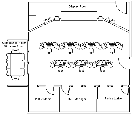
Figure 14-2: Example of a TMC Floor Plan
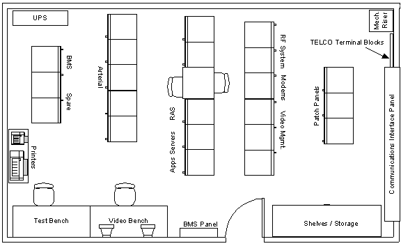
Figure 14-3: Example Layout of a TMC Computer / Peripheral Room
The operations room is the hub of the TMC. It houses the operators' workstations and display boards/video terminals used to display information about conditions in the network to the operators. The size of the operations room is dictated by the number of operator workstations that will ultimately be in the TMC, and the type and location of the information displays.
The computer/peripheral area houses the computers needed to run the freeway operations center. The size of the computer room depends upon system design decisions regarding how much computer capability will be based at the TMC as compared with that installed at hub locations in the field. Often these rooms require strict environmental controls (i.e., heating and air-conditioning). Many locations also have strict access control for this area.
The communications area can be a stand-alone area or can be combined with the computer/peripheral area. The communications area is the terminus for data entering and exiting the TMC from the field. It also serves as the distribution point for transmitting data to the rest of the system (i.e., the computer and video control systems).
Many locations like to provide a gallery or viewing area of the operations room. From this area, tours of the TMC can be conducted without interrupting the operations in the TMC. This area can also be used as a training center where trainees can monitor the operators without disturbing them.
Many TMCs also have an area set aside for the media. Some TMCs use the gallery area to service this function, but others have set aside a separate area as a media area. From this area, the media can watch what is going on in the operations center without interrupting the operations. Often, these areas have several telephones and video terminals that are available for use by the media during incidents or emergencies.
Besides these common areas, office space should be provided to those working in the TMC. The number of office spaces, again, depends upon what functions will be carried out in the TMC. Generally, office space is required for the operations supervisors, the system support staff, the maintenance supervisors, and the engineering and administrative staffs.
Some agencies have included space for their system maintenance personnel at their TMCs. If maintenance operations will be based at the TMC as well, the space provided at the TMC is based on the number of electrical maintenance personnel that will be stationed there. In addition, if the TMC is also expected to serve as an Emergency Operation Center (EOC), then additional space is needed for such items as dormitories, a large kitchen, and showers. Some locales may have mandated structural requirements for an EOC that are more stringent than for regular commercial office space. Finally, some centers house their emergency dispatch vehicles and equipment, and as such, include garage facilities.
14.2.6.2 Physical Attributes
Other notable design features related to the physical plant of the TMC are listed below:
- Raised flooring should be provided for, at minimum, the operations room, computer/peripheral room, and behind the projection display wall to allow for the ease of running communication cabling. It should be noted that good design practice calls for sealing the concrete subfloor in these rooms with a sealer to keep down dust that can be drawn up into equipment through openings in the raised floor for the equipment racks.
- The use of antistatic carpet should be utilized throughout the center. The carpet tiles that cover the raised flooring should be the same size as the raised floor tiles.
- The display wall (and the operator console surfaces) should have a flat, non-reflective finish. Control room walls should be finished in acoustic panels to reduce noise levels.
- No water pipes or tanks should be installed over critical areas such as control room or computer peripheral room. These rooms should, regardless of nearby water sources, have the sub floor graded for water run-off in the unlikely event of a flood.
- Sufficient cable raceways should be provided throughout the building to effectively manage the kilometers of cable necessary.
- Non-reflective glass should be used in the control room.
- Sufficient uninterrupted power supply and back-up diesel generator should be provided to ensure critical system stay available in the event of a power failure.
- Caution should be used in the provision of a truss or stand for the video display equipment so as not to cause electromagnetic interference with video equipment as a result of the accidental magnetism of the stand during welding. It is recommended that these stands be tested for magnetism prior to the installation of the video equipment. Should there be magnetism present, the stand should be de-magnetized prior to the video equipment being installed.
- Accommodation for fire/disaster proof storage for backup of code, documentation, and support software and tools should be provided. Although it is a good idea to archive back-ups off-site, to facilitate disaster recovery there should be some space on-site that will survive a fire and any disaster that the location may be susceptible to.
14.2.6.3 Lighting
Lighting is an important consideration in the design of a TMC. Viewing a large situation map with LED signals or a bank of CCTV monitors, for example, is not compatible with high levels of general illumination. On the other hand, many operators' tasks cannot be performed in low levels of illumination. The lighting scheme and choice of luminaries must be viewed as an integrated whole, and not designed piecemeal (6).
The greatest challenge in designing the lighting in the TMC revolves around the need to provide dim general illumination and higher levels of local illumination. Usually, a low level of illumination is provided in the operations room because of the nature of the tasks and displays used. Most centers provide supplemental lighting at each operator console. Some general recommendations related to lighting in TMCs are as follows (6):
- Indirect lighting should be employed to provide overall illumination for the control room.
- Canister fixtures should be employed to provide supplementary illumination over work areas.
- Adjustable fixtures should be used in work areas where more intense illumination is required.
14.2.6.4 Acoustics
Communications between operators can be critical, especially in emergencies. Common sources of noise in a TMC include alarms, radio/telephone communications, operator conversations, and data processing equipment. Overall, the noise level in a TMC should not so high as to interfere with normal speech between operators. The objective in designing for noise is to balance the different sound sources so that local speech is unaffected, but is sufficient to mask intrusive noise from adjacent spaces. Some general recommendations for reducing the impact of noise in the TMC include the following:
- Identify possible noise sources (including machines, telephones frequently in use, loudspeakers, and radios with speakers) during the design phase and eliminate them.
- If noise sources cannot be eliminated, consider strategies for reducing noise level, including textured or sound-deadening wall and ceiling materials.
- Consider placing noisy functions that are not tied to normal operator activity in a separate room or in an area enclosed by acoustic partitions.
14.2.6.5 Heating and Cooling
Operator comfort and performance can be affected by temperature and air quality. In designing a TMC, designers must be concerned about two issues related to the thermal environment of the TMC – the general heating, ventilating, and air conditioning (HVAC) standards for occupied buildings, and the effects of local thermal conditions related to special equipment such as computers and video display units. Sometimes, special rooms in the TMC, such as the computer/peripheral room or the communications area, may require separate heating and cooling standards. The Human Factors Handbook for Advanced Traffic Management Center Design (Reference 6) summarizes the heating and cooling standards applicable to TMCs. General standards that should be considered in the design of the heating and cooling system for TMCs include the following (6):
- Actual ventilation should be ensured by introducing fresh air into any personnel enclosure.
- Within permanent structures, effective temperature shall be maintained at not less than 18°C (65°F), and not greater than 29.5°C (85°F). The temperature of the air at floor level and at head level should not differ by more than 5.5°C (10°F). Heat build-up from equipment under the work surface (around the operator's knees and legs) greater than 3°C (5.5°F) above ambient should be avoided.
- Approximately 45 percent relative humidity should be provided at 21°C (70°F). The humidity should decrease with rising temperatures, but should remain above 15 percent to prevent irritation and drying of body tissues.
- The exhausting of air from instrumentation (video display units, system units, etc.) should be so accomplished as to avoid discomfort to users and others close to the equipment. Units should be designed so that forced-air exhausts are not directed toward the operating position, or toward other workers in their work positions.
- External surfaces that can be touched during operation should have a surface temperature that does not exceed 50°C (122°F). Surfaces intended to be touched during normal operation should not exceed 35°C (95°F).
14.2.7 Operator Workstations
Integral to any TMC are the means by which operators enter and retrieve information. Controls allow the operators to guide certain traffic parameters (e.g., traffic flow) within the limits of the center's mission. Displays provide information that operators need to monitor the status of the system and make control decisions. The operator workstation is often the primary means by which operators interact with the system. Examples of operator workstations are shown in Figure 14-4.
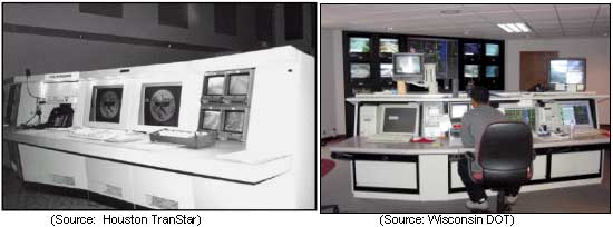
Figure 14-4: Examples of TMC Workstations
Workstation design is dependent on several issues – the layout and space availability within the TMC, the functions of the freeway management system and how those functions are allocated within the FMS software (including the level of automation), and the software itself. For example, if the decision is made that each workstation will have access to all functions in the center and there are multiple types of systems included – not all of which are able to be operated from the same platform, or some requiring larger displays or different types of interfaces – the design of the workstation will be very different than if all of the functions can be incorporated into the same software package or can be operated on the same platform. Similarly, if the control room is too small to hold separate workstations, customized fixtures designed specifically for the TMC under development may be required.
The layout of workstations and other furniture and fixtures should be specified as part of the overall work space design. In designing workstations, comfort and suitability should be considered as important issues, both of which are supported with many experience-based guidelines (Note: The Human Factors Handbook for Traffic Management Center Design (Reference 6) summarizes many of these guidelines).
Well-designed workstations and supplemental furnishings (e.g., chairs) can prevent discomfort and perhaps occupational injuries (e.g., back strain, cervical stress disorder, carpal tunnel syndrome, and repetitive stress disorders). A good design will contribute to productivity and employee health and morale, while a poor design can actually limit productivity. Designing the workplace to accommodate the characteristics and capabilities of human operators is often referred to as ergonomics. The strong movement toward ergonomic suitability has created many sources of information that support proper workstation design; however, an experienced ergonomist or human factors engineer should be consulted before a large investment is made in workstations. If possible, consultation with the TMC Operators should be employed in the design of the work centers.
Considerable changes in workstation design have occurred as freeway management systems have evolved over the last three decades. In the past, most TMCs were designed with multiple workstations, each with a specific function. For example, one workstation controlled the video surveillance system, another controlled the variable message signs, another controlled the ramp metering system, etc. This type of design required the operators to move between a series of workstations to implement a control strategy in a specific situation. Today, most control consoles are being designed so that a single operator can operate all of the subsystems from a single workstation. This generally results in better operational control over the system; however, in some situations, two or more operators may be competing for control of the same camera or monitor. Methods of setting priorities whereby multiple functions can be performed at a single workstation need to be established.
The design of individual workstations in a TMC varies depending upon the functions to be performed by the operators. All workstations should be designed to ergonomic standards. The placement of video display monitors and input devices (e.g., keyboards, mouse, trackballs, switches, etc.) should also conform to recognized standards and guidelines. Common ergonomic design problems include the following:
- Monitors placed above operators' seated line of sight.
- Operators having to look over consoles, monitors, and other equipment to view monitors on the wall.
- Inadequate or improper labeling of control features.
- Console heights not adjustable to extremely short or extremely tall operators.
Glare is one of the most common problems with video display units incorporated into workstations. Glare is generally caused by either lighting sources at the workstation or at other nearby video display units. Glare problems can be eliminated by several means, including providing glare shields between video display units and light sources; covering light sources, including windows; and using task lighting.
14.2.7.1 User Interfaces
The user interface is a software element of the system that connects the operator with machine functions in an easy-to-understand format. If the smooth execution of system functions is desired, interfaces between operators and computers must be designed properly. TMC controls and displays should be designed according to the type and quantity of information that the operators must process, and the capacities and demands of the operators who will use the information they provide.
Many troublesome human factors problems are the result of poor user interface design. Poorly designed controls and displays can affect the operations of the TMC and the operators themselves. Inadequate controls and displays can cause cognitive information processing deficiencies, faulty situation assessments and decisions, inaccurate data and command entry, occupational stress, and a general loss of operating efficiency.
The steps involved in designing acceptable user interfaces include the following:
- Develop an interface concept. This concept should be based upon knowledge of the types of interfaces available, and their strengths and weaknesses. The types of tasks to be performed through user interfaces should be considered and should be what drives the design process, rather than technology.
- Develop criteria to govern the design and evaluation of the interface. These criteria include design requirements, dialog strategies, and training requirements. The criteria should also be verified by experienced operators, traffic engineers, and others who have experience in interface design.
- Develop a "look and feel" of the user interface and conduct initial testing of the interface, using simulations of various levels of realism. (The level of realism associated with a given simulation is also called fidelity.) This type of simulation activity provides an excellent opportunity to incorporate rapid prototyping. Rapid prototyping involves using special software tools to develop and evaluate interface prototypes. Rapid prototyping techniques offer speed, flexibility, and realism to the design effort.
- Conduct user evaluation and acceptance testing of the interface. User expectations and perceptions do not always agree with those of the developers. Rigorous evaluation procedures must be employed from the very beginning of the interface design, during the prototyping activities, and as part of software / system acceptance testing. The design of user controls and displays is an iterative process. A given display, although acceptable when viewed on its own merits, may represent an inappropriate design solution when it is integrated into the TMC. Accordingly, an owner or agency should not buy off on the interface (i.e., "accept" it) until all of the software has been integrated and they can test all of the features of the final system through the interface.
- Develop the user interface for the full system implementation.
Examples of user interface screens are provided in Figure 14-5.
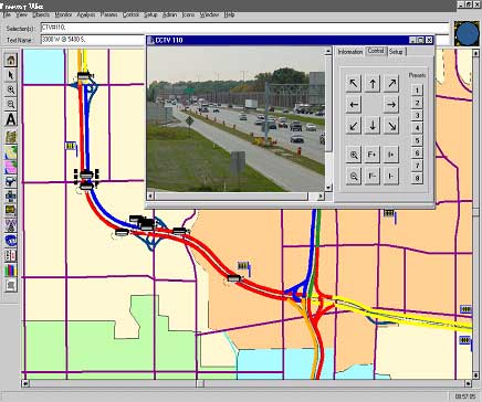
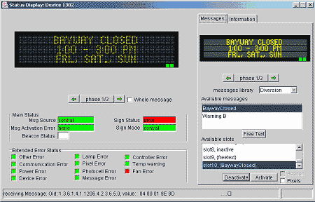
Figure 14-5: Examples of User Interface Control Screens