Virginia Demonstration Project: Rapid Removal and Replacement of U.S. 15/29 Bridge Over Broad Run Near Gainesville, VA
slide 1: Rt. 15/29 (SBL) Bridge Superstructure Replacement and Roadway Widening
March 5, 2009
Nicholas J. Roper
NOVA District Bridge Engineer
Robert F. Price
Resident Administrator of Loudoun/Prince William Construction
Virginia Department of Transportation
slide notes:
slide 2: Prior to Construction
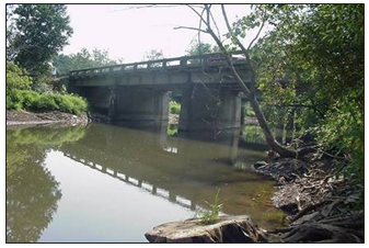 West side view of SBL bridge prior to construction |
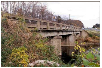 East side view of SBL bridge prior to construction |
slide notes:
None
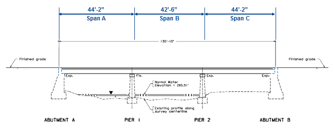
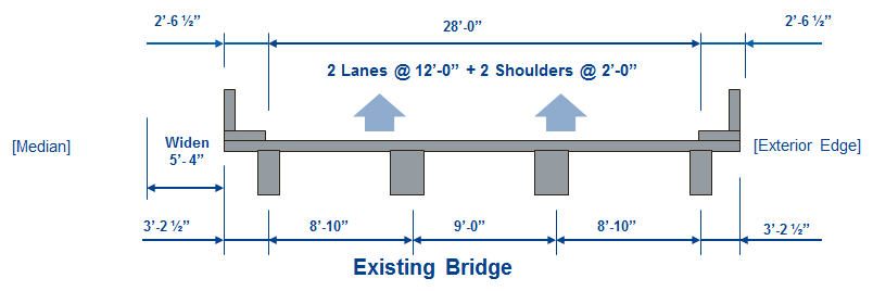
slide 3: Existing Bridge Elevation
slide notes:
None
slide 4: Project Information
- Location: The Route 15/29 (SBL) Bridge Superstructure Replacement and Roadway Widening Project over Broad Run is located in Prince William County, 0.55 Mile North of Route 215.
- Scope: Work includes replace and widen existing bridge superstructures with offsite-fabricated superstructure segments, substructure concrete widening and repairs, re-alignment and approach work.
- Superstructure: 3-Span, Concrete T beam, Simply Supported
- Substructure: Wall type piers and abutments
- Year Built: 1952
- ADT: 25,000
- Condition: Structurally deficient and functionally obsolete.
slide notes:
None
slide 5: Traffic Impacts Identification and Mitigation – Design Phase
- Analysis of Impacts
- Traffic analysis, to show the impact of closing a lane for 24 hours, was performed by Simulation Modeling . The data used was based on both published VDOT traffic data as well as the site-specific traffic counts obtained during the project.
- The results of the analysis showed that conventional bridge construction caused a significant daily traffic backup – 1.5 miles – for the duration of the construction (100 days), and resulted in at least $15M in user cost, due to traffic delays only
- Identification of traffic impact mitigation strategies
- Implement Accelerated Bridge Construction (ABC) method
- ABC during low volume traffic periods only – night construction
- Phase ABC if the construction time exceeds low volume traffic period
slide notes:
None
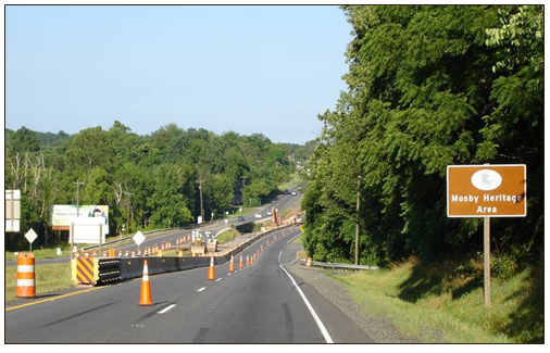
slide 6: Project Limits
Project limits within the Buckland Historical District and the Mosby Heritage Area
slide notes:
None
slide 7: Construction Concept
slide notes:
None
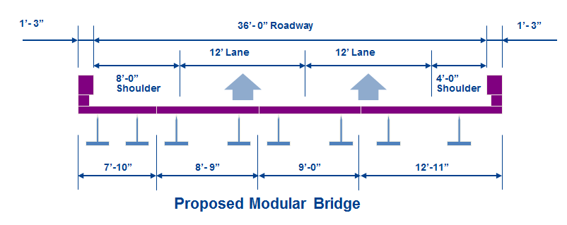
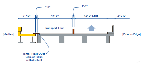
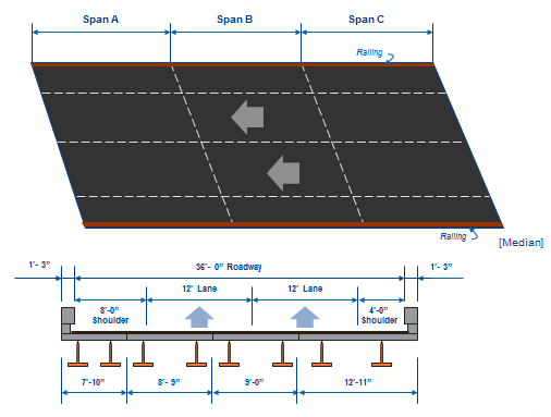
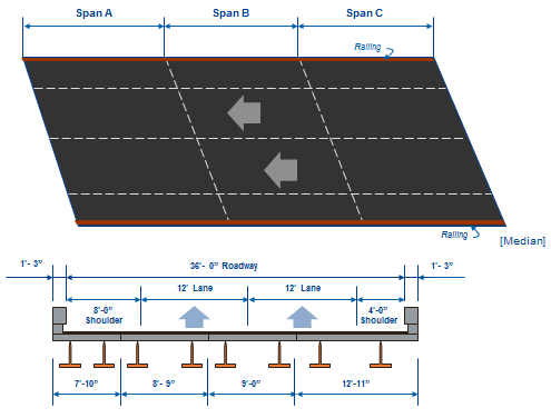
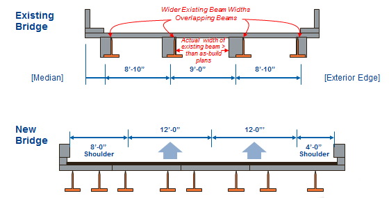
slide 8: Typical Sections
slide notes:
None
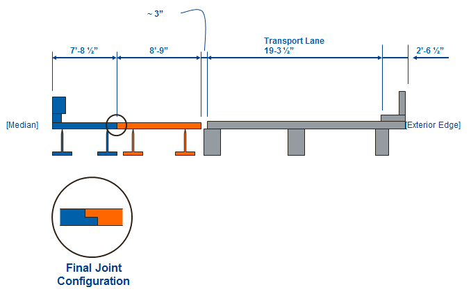
slide 9: Proposed Modular Structure
- Module Configuration:
- Each Module Consists of a Prefabricated Conc. Deck on Two Steel Beams
- Module Width Arrangement in Transverse Section: (7'-10") (8'- 9") (9'-0")(12'- 11")
- Module Length = Span Length (~ 44')
- Max. Module Weight = ~35 tons (~30 tons w/ Lightweight Concrete)
- Longitudinal Joints between Modules:
- Grouted/Waterproofed Keyways
- Diaphragms between Modules:
- Field Installed Steel Diaphragms
- Deck Parapets:
- Plant Cast Concrete
- Asphalt Overlay:
- 3" Thick with Waterproof Membrane
slide notes:
None
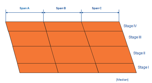
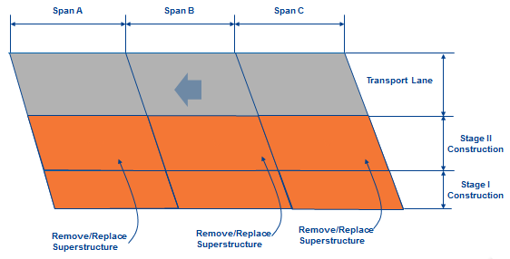
slide 10: Proposed Sequence of Construction
slide notes:
Reduced Scope of Work Plan: Replacing Bridge Deck and Use Existing Bridge substructure.
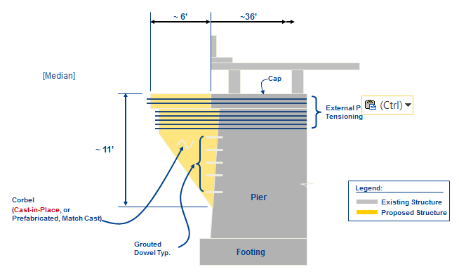
slide 11: Extending Pier with External PT
slide notes:
None
slide 12: Extending Abutment A (Typical)
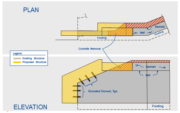
slide notes:
None
slide 13: Proposed Construction – Stage I at Night: 9 p.m. to 5 a.m.
slide notes:
Reduced Scope of Work Plan: Replacing Bridge Deck and Use Existing Bridge substructure
slide 14: Proposed Construction – Stage I Night
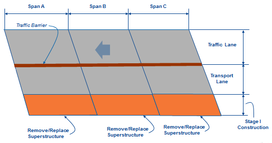
Note: Stages III and IV are similar.
slide notes:
Reduced Scope of Work Plan: Replacing Bridge Deck and Use Existing Bridge substructure.
slide 15: Stage II MOT for Nighttime Construction
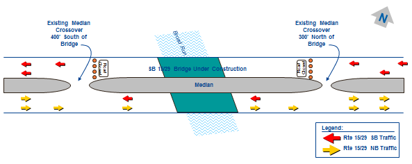
- Close the SB bridge to traffic from 9 p.m. to 5 a.m.
- Route the SB traffic on NB via the crossover 300' north of the bridge.
- Route the SB traffic back on SB via the crossover 400' south of the bridge
- Maintain both lanes of traffic on SB bridge from 5 a.m. to 9 p.m.
slide notes:
Reduced Scope of Work Plan: Replacing Bridge Deck and Use Existing Bridge substructure
slide 16: Proposed Construction – Stage II at Night: 9 p.m. to 5 a.m.
slide notes:
None
slide 17: Proposed Construction –Stage II at Night
slide notes:
Reduced Scope of Work Plan: Replacing Bridge Deck and Use Existing Bridge substructure.
slide 18: Completed Structure
slide notes:
Reduced Scope of Work Plan: Replacing Bridge Deck and Use Existing Bridge substructure.
slide 19: Construction Phase
slide notes:
None
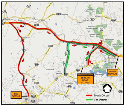
slide 20: Traffic Impacts Identification and Mitigation – Construction Phase
- Final TMP
- Use ABC during weekends: Begin Friday Mid-night; End Sunday PM.
- Detour Traffic during ABC
- Designate separate detour for trucks
- Repeat ABC/detour 3 weekends to complete construction
- Provide Complete MOT Plans with traffic signs, VMS, etc.
- Incident Management Plan during construction
slide notes:
None
slide 21: Revised Construction Sequence –Revised MOT Plan for Weekend Closures
slide notes:
None
slide 22: Revised Construction of Span A
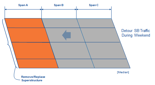
slide notes:
Reduced Scope of Work Plan: Replacing Bridge Deck and Use Existing Bridge substructure.
slide 23: Revised Construction of Span B
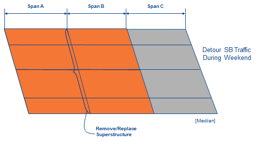
slide notes:
Reduced Scope of Work Plan: Replacing Bridge Deck and Use Existing Bridge substructure.
slide 24: Revised Construction of Span C
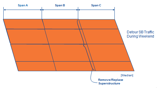
slide notes:
Reduced Scope of Work Plan: Replacing Bridge Deck and Use Existing Bridge substructure.
slide 25: Completed Structure
slide notes:
Reduced Scope of Work Plan: Replacing Bridge Deck and Use Existing Bridge substructure.
slide 26: Lessons Learned – Traffic Management with Accelerated Bridge Construction
- Achievement of Project Goals
- Project was completed with minimum disruption of traffic and inconvenience to public, and full satisfaction of the Buckland community.
- Superstructure construction reduced from 100 days to 6 days
- Lessons Learned
- Accelerated Bridge Construction is slightly more expensive than the conventional construction, but it could result in significant savings in User cost and eliminate inconvenience during construction
- Public communication essential to success of the TMP
- Future Directions on Traffic Operations Management for High Impact Projects
- Accelerated Bridge Construction as a valid construction option for projects in congested areas where full traffic capacity during peak hours must be maintained
slide notes:
None
slide 27: Lessons Learned – Conflicts With Beams
- Encourage full detailed survey/as-built investigation during Preliminary Engineering Phase.
- Design should use maximum tolerances to allow for field adjustments.
- Designers need to insure all specified materials are readily available (standard typical beam sizes).
slide notes:
None
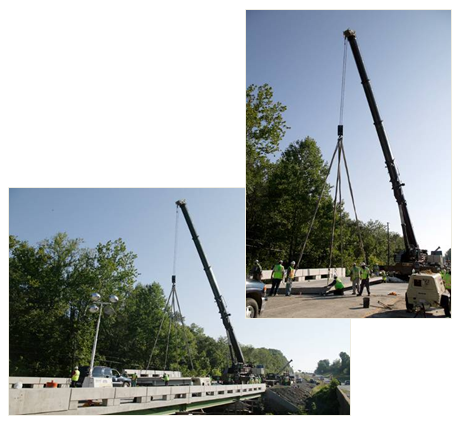
slide 28: Lessons Learned (Continued) – Crane Issues
- Larger crane required
- Limited work area
slide notes:
None
slide 29:
slide notes:
None
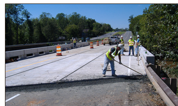
slide 30: Placing Asphalt at the Abutment and Sealing Deck Joints
slide notes:
None
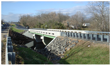
slide 31: Completed Structure with Asphalt Overlay
slide notes:
None
Return to List of Presentations