You may not be familiar with the term “life cycle model”. A life cycle model describes the distinct stages of a system’s “life”. Generally, a system moves through different stages: planning, concept, development, implementation, operations and support, and retirement. The role of the systems engineer encompasses the entire life cycle of the system with principal focus on development and implementation – the stages when the system is created. There are several approaches that can be used to develop a system:
Sequential Methods – Sequential methods are often called the “waterfall” approach since the work flows through sequential steps from initiation to completion. A sequential approach can be very efficient if you know exactly what you want and there is little risk of change over the course of the system development.
Incremental Methods - The most common incremental method is really a variation of a sequential method. It may have incremental aspects relating to design and development of the system, but a key aspect of this approach is that the complete system is initially planned and specified. In this case, you are making one pass through the first part of the development process to determine the needs addressed and the requirements of the system. Several projects then iterate through the latter part of the development process for each phased increment.
Iterative Methods - There are several development methods that employ iterative approaches throughout the development process. In these methods, developers plan, specify, and implement an initial system capability. Following the initial development, which may or may not be determined acceptable for operational use, this process leverages experience gained with the initial system to define the next iteration to fix problems and extend capabilities. Iterative methods have been widely adopted for software projects that use Agile development to respond effectively to change, risk, and uncertainty.
The best method depends on how much you know about the system that you want to implement, whether you have all the funds that you need to implement the system in one fell swoop, your agency and contractor capabilities, and your assessment of the risks.
Sequential methods are characterized by a series of defined processes with gates that are passed through between each process. These gates are usually deliverables such as a Concept of Operation or Requirements document. Traceability between the processes is another trait of a sequential method as applied to project development. This approach is frequently called the “waterfall” approach since the work flows in a single direction from initiation to completion, with limited opportunity to revise products from prior portions of a project. Such an approach works well if the vision is clear, the requirements are well understood and stable, and there is sufficient funding. The problem is that there isn’t a lot of flexibility or opportunity for recovery if your vision or the requirements change substantially.
The two most common sequential models in the transportation domain are the traditional transportation project development process and the Vee model.
Transportation projects are identified and funded through transportation planning and programming/budgeting phases. Funded projects are then implemented using a process similar to the traditional capital project development process shown in Figure 3, but the exact process used for ITS projects will vary with the type of project. For example, ITS projects that install only field equipment (e.g., dynamic message signs) would use a process that is very close to the traditional process shown in Figure 3. ITS projects that involve hardware and software development and integration would require additional systems engineering analyses that would be significant extensions to the traditional process.
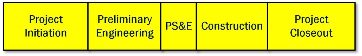
Figure 3: The Traditional Transportation Project Development Process
(Source: FHWA)
While project development processes vary from state to state and from organization to organization in each state, the transportation project development process tends to have the same major steps.
· Project Initiation – In this step, the project manager is identified, the project team is assembled, and the project development is planned. A high-level definition of the project is developed, costs are estimated, and the required forms and checklists are completed to garner approval for the project from the sponsoring and funding agency(ies). For FHWA and FTA, this is a critical point in the process where approval to proceed is given and federal funds are obligated.
· Preliminary Engineering – In the traditional capital project development process, environmental, right-of-way, and other studies are performed depending on the type of project. These studies result in better understanding of the project requirements and constraints. ITS projects that include a construction component will require these same studies as well as additional engineering analyses to fully specify the project requirements for the ITS portion of the project. Note that from a federal aid perspective, “preliminary engineering” also includes PS&E. PS&E is split out separately here to differentiate between requirements-oriented and design-oriented steps in the traditional project development process.
· Plans, Specifications, and Estimates (PS&E) – The detailed design for the project, complete with detailed project specifications, estimates of material needs, and associated costs are documented. In a traditional construction project, this process step provides companies with all the information they need to develop an accurate bid. Construction elements within an ITS project will also require traditional design documentation (i.e., layout sheets, plan and elevation views, cross-section details, etc.). Design documentation is also required for the hardware and software components in an ITS project, but it takes the form of high-level design, interface specification, and detailed hardware and software specifications.
· Construction – The project is built. For a traditional transportation project, this is construction of the actual physical improvement. For an ITS project, this includes the procurement and implementation of the actual hardware, software, and enabling products (e.g., manuals, operating procedures, and training). This step also includes inspection of the physical improvement(s) and integration and testing of the implemented system(s).
· Project Closeout – After final inspection/testing, the completed project is accepted, as-built plans are created, and a project history file is completed.
Another important example of a sequential method is the Vee model shown in Figure 4. Since it was first developed in the 1980s, the Vee model has been refined and applied in many different industries.
As shown in the Vee, the systems engineering approach defines project requirements before technology choices are made and the system is implemented. On the left side of the Vee, the system definition progresses from a general user view of the system to a detailed specification of the system design. The system is decomposed into subsystems, and the subsystems are decomposed into components – a large system may be broken into smaller and smaller pieces through many layers of decomposition. As the system is decomposed, the requirements are also decomposed into more specific requirements that are allocated to the system components.
As development progresses, a series of documented baselines are established that support the steps that follow. For example, a consensus Concept of Operations supports system requirements development. A baseline set of system requirements then supports system design. The hardware and software are implemented at the bottom of the Vee, and the components of the system are then integrated and verified in iterative fashion on the right. Ultimately, the completed system is validated to measure how well it meets the user’s needs. (Each of the steps in the Vee are defined in detail in Chapter 3.)
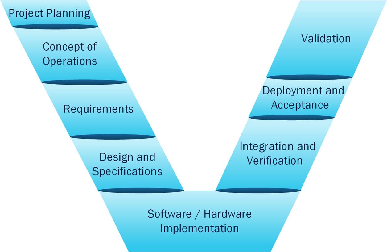
Figure 4: Sequential Method: Vee Model
(Source: FHWA)
While these two models may look quite different, you can easily relate the steps of the traditional transportation project development process to the Vee model. There is not quite a one-to-one relationship between the different stages or phases of the models, but since each are versions of sequential models, they line up fairly well.
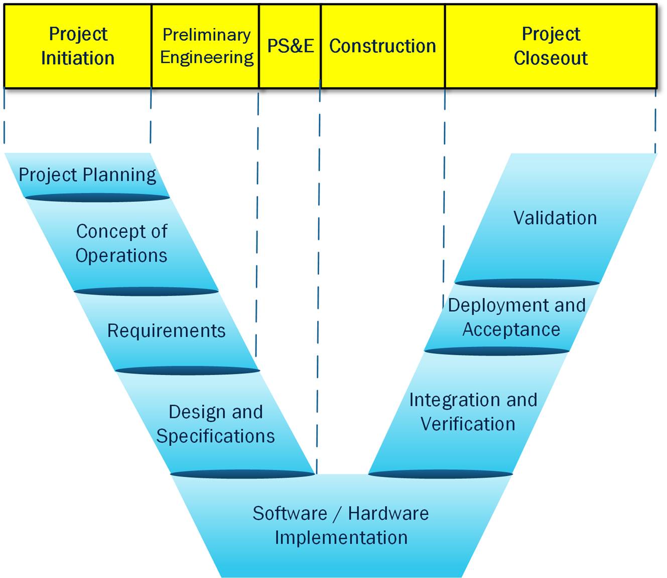
Figure 5: Comparison of Sequential Models
(Source: FHWA)
In the previous section, we were focused on the life of a single project from initiation to close out. As we noted in Section 2.4, there are important planning steps that occur before the project is initiated. The system life cycle also extends beyond project closure to include operations and maintenance and ultimate retirement of the system. This broader system context is reflected in “wings” that are added to the Vee model that we use for ITS, as shown in Figure 6. This figure also distinguishes between a system life cycle and a project life cycle. The project life cycle encompasses all the activities of a project, how a project is planned, designed, developed and tested and covers from inception to completion for a specific project.
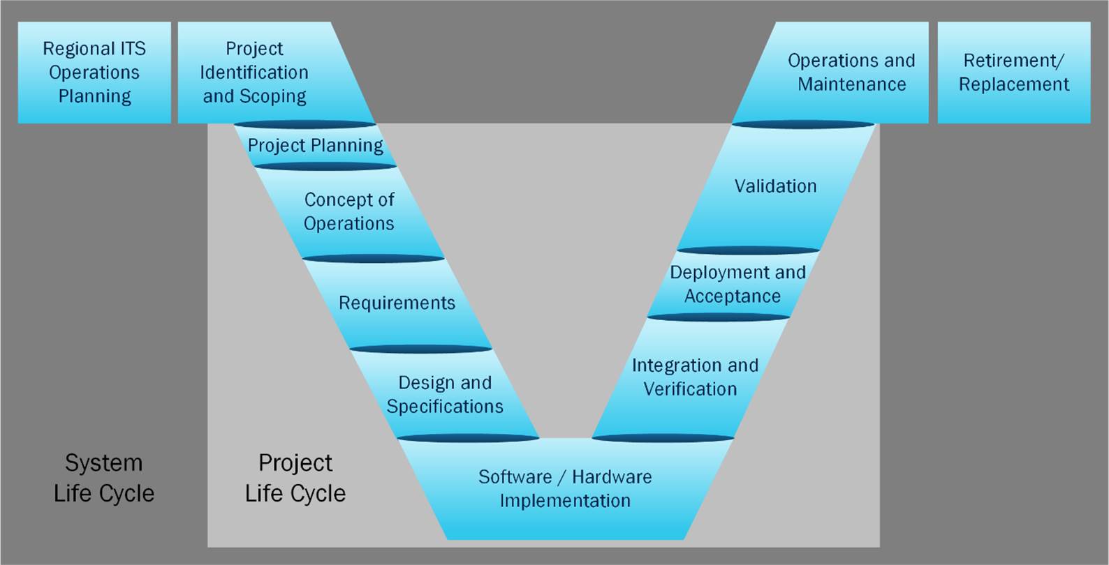
Figure 6: System vs Project Life Cycle
(Source: FHWA)
Most transportation systems are implemented incrementally through multiple projects, requiring multiple passes through the sequential project development process. A key aspect of the incremental method is that the complete system is initially planned and specified. In this case, you are making one pass through the first part of the development process to determine the needs addressed and the requirements of the system. One or several projects then iterate through the latter part of the development process for each phased increment. This is a common strategy for a phased deployment of a system with stable system requirements and design, such as for field equipment deployment where a core system can be deployed to provide initial capability and additional components can be incrementally implemented and deployed across a metropolitan area in several phases and several projects. An example of adding an incremental aspect to the Vee model is shown below.
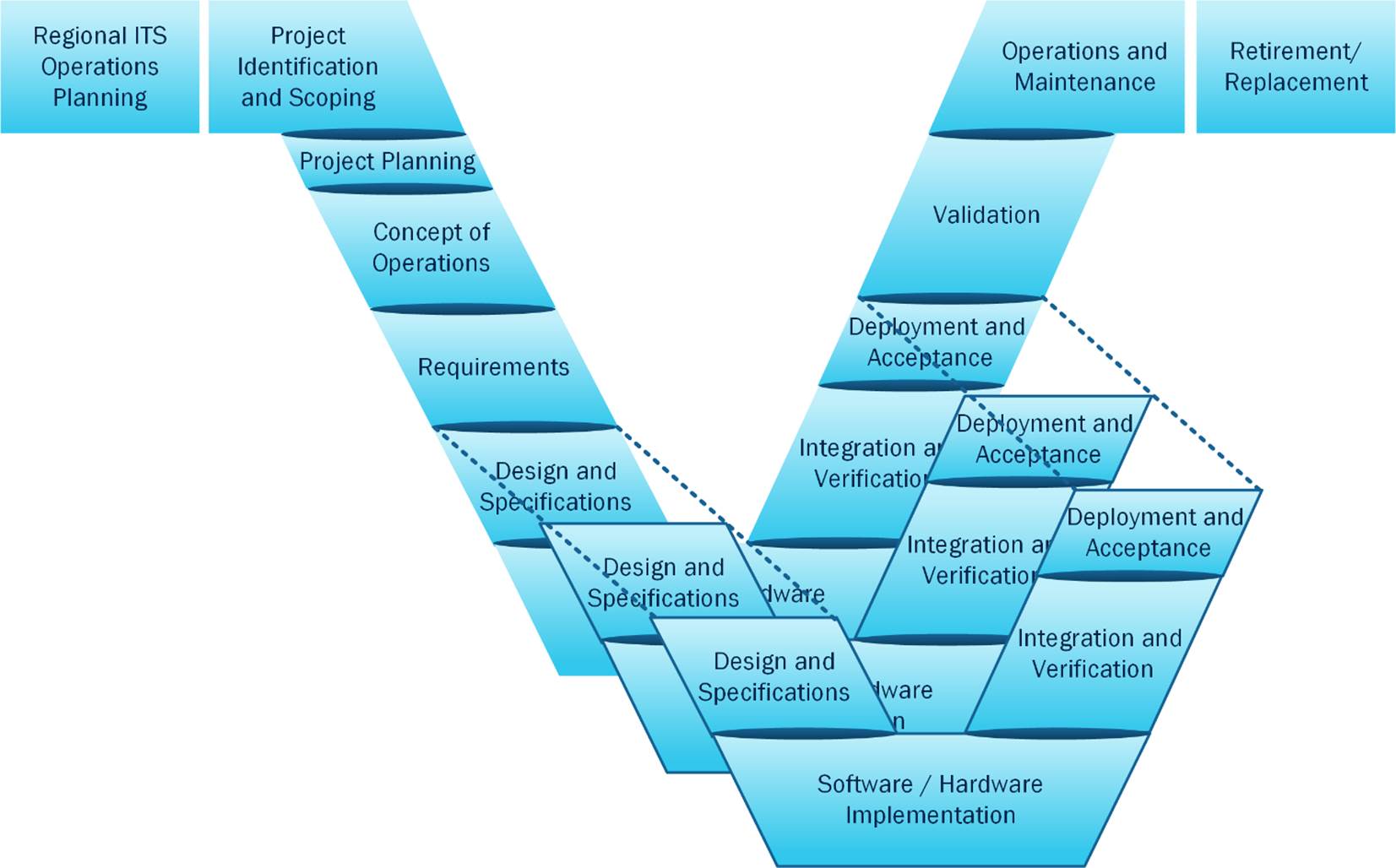
Figure 7: Systems Engineering Vee with Multiple Incremental Projects
(Source: FHWA)
There are several development methods that employ iterative approaches throughout the development process. In these methods, developers plan, specify, and implement an initial system capability. Following the initial development, which may or may not be determined acceptable for operational use, this process leverages experience gained with the initial system to define the next iteration to fix problems and extend capabilities. In each iteration of the development process, prior efforts can be revised and refined including the Concept of Operations, system requirements, and design, as necessary. This process is continued with successive iterative refinements until the system is complete. These iterative approaches are often used when the requirements are unclear from the beginning, or the stakeholder wishes to hold the system of interest open to the possibilities of inserting new technology or capabilities. As such, they are not widely applicable to ITS projects.
One key type of iterative method, described under the term Agile development, has been considered for use for ITS projects. The discussion below is taken from the FHWA document Applying Scrum Methods to ITS Projects.
Agile enterprise concepts were formulated in several commercial domains (e.g., automotive, semiconductor, telecommunications) and the military. Agile system frameworks and agile enterprise reference models were being developed in the mid to late 1990s, and eventually migrated over to the software development community.
In the early 2000’s a group of software development experts developed The Manifesto for Agile Software Development” and the “12 Principles Behind the Agile Manifesto.” The Agile Manifesto and the 12 supporting principles were written specifically as a philosophy for software development teams to easily adjust to stakeholder and user needs by focusing on people and interactions, not processes and tools. Using agile development allows project teams to incrementally deliver planned functionality earlier in the development cycle. Since then, Agile methods have been embraced by the DOD and NASA.
While a number of Agile methodologies have been developed over the past 20 years, one of the most common is referred to as the Scrum method. Scrum is an iterative agile methodology for managing product development “within which people can address complex adaptive problems, while productively and creatively delivering products of high value”[1] The original idea of the agile concept was to provide an alternative to the waterfall method for software development, providing an alternative to documentation driven, heavyweight software development processes. The idea was to incrementally deliver planned functionality earlier in the development cycle. Scrum focuses a team’s efforts on quick and incremental delivery of the product with regular feedback from stakeholders. This framework allows product development to respond quickly to changing requirements and adapt to evolving technologies.
A key takeaway from the FHWA document is where, in the context of ITS projects, are Agile methods appropriate.
Characteristics for projects that may be better suited to using Agile (or Scrum) include:
· The client does not have a good vision of specific product (or a single unit) functions and needs to see something tangible to help them decide on said functions
· System upgrades to existing systems where the new/needed functionality is well understood by the stakeholders
· New human interfaces that require frequent user trials to perfect the interface
· Web sites that require frequent user trials to perfect functionality
· Functionality that can be delivered incrementally
Characteristics for projects that are not suited to using Agile (or Scrum) include:
· Systems or system components dealing with safety critical or safety of life features/functions
· Systems requiring long-term maintenance and/or thoroughly documented project design decisions
· Systems consisting of high levels of integrated disparate systems
There are also several challenges that should be considered before adopting Agile methods (or Scrum) to your project:
· Don’t use Agile methods (or Scrum) when safety of life, long-term maintenance, and integrating large disparate systems are at risk
· Consider the skill set, staff knowledge, and resources required when using Agile methods (or Scrum)
· Remember Agile is new to ITS community and implementation is still evolving
Below is a short description of the Scrum methodology. For additional information about Scrum, and its use for ITS projects, refer to the FHWA document Applying Scrum Methods to ITS Projects (https://rosap.ntl.bts.gov/view/dot/32681).
Scrum prescribes a process of events and artifacts (deliverables/ by-products of Scrum development) that center around a time-boxed (time-constrained) iteration called a Sprint. Once a Sprint begins, its duration is fixed and cannot be shortened or lengthened. Typically, a Sprint will last from two to four weeks with two weeks being the most common. The basic Scrum Method is described below and illustrated in Figure 8.
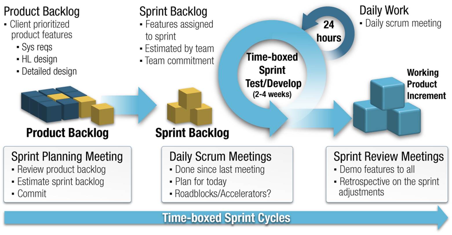
Figure 8: Illustration of Scrum Method
(Source: FHWA)
[1] Applying Scrum Methods to ITS Projects, Final Report — August 2017, Publication Number: FHWA-JPO-17-508