6. Hardware Testing
6.1 Overview
This chapter focuses on the testing of hardware or physical devices including traffic controllers, detection systems, ramp controllers, and dynamic message signs and TMC devices such as workstations, video projectors, and communications equipment. While software is usually part of these devices since most include computers (microprocessors), it is typically "embedded" (classified as firmware) or an integral part of the device. The hardware test program is intended to cover the device testing from the device testing from prototype to final deployment.
Throughout this chapter, the various phases of testing are presented, from prototype testing during early phases of the product development through site testing, which occurs once the equipment is installed at its final location. The degree of testing required will depend on the maturity and track record or installation history of the device (product), the number of devices purchased, the cost of the testing, and the risk of system failure caused by problems with the device. For general classification purposes, the maturity of the device will be categorized based on its history, which can vary from standard devices (typically standard product), to modified devices, to new or custom devices developed for a specific deployment.
The following sections will discuss the device testing in phases starting with the development of a prototype to the final acceptance testing. In the installation phases and beyond, the test activities are the same regardless of the maturity of the product (new, existing, or modified).
6.2 What Types of Testing Should Be Considered?
The testing for a device or product can be broken down into the following general categories:
- Design verification.
- Functionality.
- Mechanical and construction.
- Standards compliance (NTCIP and others).
- Environmental.
- Serviceability.
Each of these will be discussed to gain a better understanding of what is meant and what is required for each.
The following sections describe the elements of a complete testing program based on the assumption that the device being offered is a new design or custom product, and hence the device should be subjected to all aspects of requirements verification. After this initial discussion of the worst case testing program, this guide will consider what steps can probably be eliminated or minimized for standard products and modified products as described above.
6.2.1 Design Verification
Most procurement specifications will include design requirements for the ITS devices. If these requirements are not explicitly included in the procurement specifications, they may be invoked through referenced standards such as the CALTRANS Traffic Engineering Electrical Specification (TEES) or the equivalent NY State Standards. 17 These requirements typically include such physical issues as choice of hardware (see mechanical and construction below), choice of materials, voltage margins, visibility of indicators, speed of devices, and component thermal restrictions. These design requirements may also include limitations on the mounting of electronic components, insertion and removal force, connector plating, labeling of electronic components, printed circuit board layout markings, and custom components. The agency is cautioned that re-use of "existing" procurement specifications can often lead to references that may be outdated or obsolete, such as retired military, or "MIL," standards. In fact, if you use MIL standards, the question of whether your agency is capable of actually performing tests to verify conformance to MIL standards must be asked. If you can't or don't intend to actually test for compliance with these standards, don't put them in the specifications unless you are willing to accept a certificate of compliance from the vendor for these tests.
There may also be outdated restrictions on electronic construction techniques, such as a prohibition of multi-layer printed circuit boards, and requirements for integrated circuit sockets that are no longer valid and would prohibit many of today's newer technologies. It is important that the procurement specifications be reviewed and updated by a person who is knowledgeable of current electronic designs and construction methods to ensure that all external references are valid and current and that manufacturing technology has likewise been updated to reflect current techniques. Because of the specialized skills required, most agencies and many consulting firms will need to supplement their staff by outsourcing this work. When an agency engages a consultant to prepare their procurement specification, how and by whom (e.g., sub-consultant or on-staff engineer) this expertise will be provided should be well defined.
As a case in point, the following are "design requirements" typically found in ITS device procurement specifications and therefore must be verified for product acceptance by either the agency or its consultant. Note in example requirement 1.3.2.3 below, it may be difficult or impossible to read the manufacturing dates on all the PC board components unless they are physically removed and inspected under a magnifying glass or microscope. However, this requirement could be verified during the manufacturing process, before the components are inserted and wave soldered on the PC boards.
|
REAL WORLD EXAMPLE: (taken from CALTRANS TEES August 200218). 1.3.2.3No component shall be provided where the manufactured date is 3 years older than the contract award date. The design life of all components, operating for 24 hours a day and operating in their circuit application, shall be 10 years or longer.19 |
It is recommended that these types of design requirements be validated with respect to the rationale behind why they have been included in the specification (e.g., what value do they add to the product's reliability, electromagnetic compatibility, etc.) and what methods will be used to verify them. Requiring vendor certification that the design meets these requirements and a performance bond with an extended full replacement warranty on the entire device might accomplish the same objective without the agency bearing the cost of extensive design verification testing. For new or custom devices, the device design must be reviewed for conformance to these types of requirements and this type of inspection will require specialized technical expertise to review design drawings, data sheets, etc.
The goal of the design review is to examine areas of the design that may be subjected to electrical, mechanical, or thermal stress. Several areas of a device's electronic design typically warrant close design review; these include the power supply design and the external interfaces for voltage and power dissipation. These areas of a design are often subjected to the most stress due to AC power line regulation and the characteristics of the external devices. Design short cuts in these circuits can affect the long-term reliability of the device. It is also necessary to review the manufacturer's data sheets to ensure that the components being provided are truly rated for operation over the NEMA or TEES temperature ranges; this is often the difference between "commercial" and "industrial" rated components. It is common to include a requirement that non component shall be used in a manner which is inconsistent with the manufacturer's recommendations without explicit written information from the manufacturer stating that the vendor's use is acceptable.
As with the environmental testing (below), it is important that the specifications identify the design requirements and that the test (and inspection) procedure include verification of these requirements. The vendor should be required to assemble a set of manufacturer data sheets for all components and have those included in the reference material provided as part of the test procedure. Often the best approach to this aspect of the "testing" (inspection) of the product is to require that the vendor provide engineering work sheets that show the thermal characteristics of the device, demonstrate how the components are maintained within their junction temperatures for all ambient temperatures required, and how the voltage ratings of the interface devices were determined.
Experience has shown that when vendors are aware that the device will be inspected for conformance to all of the design requirements, they will revisit their design decisions and/or start the process of submitting a request for an exception. Often, by requiring that the vendor develop the test procedures and inspection "check sheets," they will address potential problems before the testing.
|
EXAMPLE: During the development of custom telemetry equipment for the Manhattan Signal System, the vendor was required to develop a test procedure that included full and complete verification of all of the design requirements in addition to all of the functional and performance requirements listed in the specifications. Initial test procedures delivered to the agency did not include inspection for the design requirements. When the agency insisted that "all aspects of the specification requirements be demonstrated," the vendor conducted their internal review, which revealed that their power supply design and interface circuitry would not meet the specified requirements. The vendor modified the design and submitted proof that the design met the requirements, and the units have provided long-term (> 15 years) reliable operation. EXAMPLE TEST STEPS TAKEN FROM A DMS FACTORY INSPECTION TEST PROCEDURE: This test procedure included a complete matrix of all of specification requirements and a method used to verify all such requirements. Only two of the requirements are shown here, but the test procedure included design review of the power supplies, driver circuits, and such details as component mounting and printed circuit board labeling. 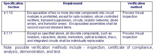
|
6.2.2 Electrical, Mechanical and Construction Verification
Different devices will have different mechanical and construction requirements. This aspect of the testing program should include conformance to mechanical requirements such as weight, height, depth, and width, where specified. For example, for dynamic message signs, it is important that the vendor's design adhere to the specifications for these parameters because they directly affect the design of the structure and its installation (assuming that the structure was properly designed). For other ITS devices such as traffic controllers or field cabinets, it may be essential that they match an existing foundation size, mounting footprint, or existing cabinet. For some devices such as detectors, communications equipment, and controllers, it may be shelf limitations, rack height and depth, or printed circuit card profile.
Aspects of the mechanical design and construction must also be inspected or tested to ensure that the welding is proper, that the paint adhesion, thickness, harness, and color are proper, and that the material was properly treated before assembly. Some agencies have developed specific test procedures for parameters such as paint hardness (e.g., writing with a HB pencil which must not leave a mark) and paint color (the agency's specified color samples are compared to the painted cabinet). Some parameters (e.g., paint thickness) require that the thickness of the paint be measured on a cross section of a sample. In summary, although some of these requirements can be observed, many may require certification by the vendor and an inspection or analysis by a third party laboratory.
Other construction requirements may require inspecting for all stainless steel hardware, prohibitions on sheet metal screws and pop-rivets, and specific requirements for wire protection against chaffing and abrasion, and the use of wire harnessing, terminal block types, wire terminations, wire labeling, and wire colors and gauges. A design and construction checklist developed from these specification requirements (and other invoked standards) should be used during this aspect of testing and inspection for compliance verification.
The procurement specifications should specify which party develops the checklist. Typically, the vendor creates this checklist for review and approval by the agency. The agency in turn, must verify that all of the requirements identified in the procurement specifications (and invoked standards20) are included in the checklist. The advantage of requiring that the vendor develop the checklist is that as the vendor develops the list, they are forced to review the details of the specifications and address potential areas of non-conformance before the formal factory testing. There have been instances where vendors have discovered areas of their own non-compliance during the development of this procedure; they can then work with the agency to accept the deviation or alter their design without the impending failure of a factory acceptance test. Sometimes, such deviations are inconsequential in nature and may reflect improvements in the overall product design. By reviewing the issues before the formal test, both the vendor and the agency are able to identify a workable solution without the pressures often associated with a factory acceptance test.
For design requirements such as cabinet doors, one needs to inspect the latches and locks, the gasket material, and the adhesion of same. If the specifications for the cabinet include specific airflow requirements, the vendor should be required to show that the design of the fan, filter, or louver systems are sufficient to provide the required airflow. This must generally be done through airflow calculations (analysis) based on the openings, filter, and fan characteristics. Associated components and design characteristics such as the thermostat, fan bearings, fastener and filter types used, component locations and accessibility for replacement and maintenance, and component labeling should also be inspected.
Verification of water leakage (entry) requirements will generally be a combination of inspection and actual water testing. To test for water leakage, the entire cabinet (e.g., controller, DMS, etc.) should be subjected to water flow based on the specification requirements that reflect the expected environmental conditions and maintenance activities at the installation site. This should include driving rain on all surfaces as a minimum and high pressure washing of sign faces. While not quantitative in nature, some agencies simply subject the cabinet (or sign) to the water spray from a typical garden hose held at a 45-degree angle from the ground. This test practice may not be sufficient and does not reflect the real world environment. A specific test designed to verify the expected environmental conditions and maintenance activities should be used. For example, cabinets supplied to meet CALTRANS TEES specification requirements are tested by subjecting them to the spray from an irrigation sprinkler of a specific type with a specific volume of water. When performing such a test, white newspaper (the type used for packing) can be placed into the cabinet and then inspected for signs of water after the test. Cabinet inspections should include design characteristics such as how various joints are constructed and sealed. The inspection should consider what happens as gaskets age or if the gasket material is damaged. Examine the cabinet design to determine what happens when (not if) water does enter around the gasket area or through the louvers. A good design will anticipate this life cycle problem and will ensure that the mechanical design is such that any water entering the cabinet is safely managed so that it does not damage any of the components or compromise the integrity, operation, or utility of the device.
As noted earlier, the testing procedure can only verify the requirements documented in the specification. In order to require that the vendor conduct these tests and inspections, the procurement specification must address all of these issues in either an explicit manner (e.g., "all hardware shall be stainless steel") or in a functional manner (e.g., "the device shall ensure that as the gasket ages and the product is serviced, water cannot cause damage or improper operation to the device or its components"). The requirements should be explicit and quantifiable such that verification by one of the test methods (inspection, certificate of compliance, demonstration or test) is not subject to interpretation. In the above example the requirement phrase "water cannot cause damage or improper operation" is subjective and not easily verified - in general negative statements in requirements should be avoided, they are difficult or impossible to verify. This example's requirements language should be replace by a positive statement like "cabinet drainage holes shall be provided to allow for water that intrudes into the interior of the cabinet to self drain; interior components shall be mounted at least 2 inches above the bottom of the cabinet; and all electrical connections shall be covered with water spray shield."
While you can't make all of your tests totally objective, you have to be careful how you deal with things that could be judged as subjective. In particular, there should be a stated methodology in the procurement specification for how the agency intends to resolve such conflicts. For example, "should a conflict arise with respect to satisfaction of any requirement that may be subject to interpretation, the agency shall have the right to accept or reject the vendor's interpretation and test results offered as proof of compliance, and shall provide a requirement clarification and/or set specific criteria for compliance for a re-test." This type of statement in a procurement specification would serve notice to vendors that they need to thoroughly review the specification requirements and ensure that the requirements are clear, unambiguous, and not subject to interpretation. Any requirements that don't meet this standard should be questioned and clarified in the final procurement documents. This is an area where careful document review before the bid will lead to pre-bid questions for clarification. Then all bidders will understand the intent and intended testing that will be performed.
Some of the requirements may need more explicit mechanical design review to determine if the structural integrity of the product is sufficient (e.g., design of a large walk-in dynamic message sign) and that the welding meets American Welding Society (AWS) standards. This may require that a welding inspection firm be hired to x-ray and verify the welds. For a less costly approach, the agency could require that the vendor provide certification that the welders, who actually constructed the device, have been properly trained and certified by the AWS and that such certification is up to date. An outside inspection firm could be hired to inspect some of the more critical welds and those made at the installation site (if any) to provide added confidence. For installation of an over-the-road device, the agency should request that a State licensed structural engineer be responsible for and oversee the design and seal all structural documents.
6.2.3 Environmental
Environmental testing verifies that the product operates properly under the field conditions of the expected installation site and typically includes temperature, humidity, vibration, shock, and electrical variations. This aspect of testing is usually the most extensive and complex required for any product.
There are a number of industry-accepted references for the environmental and electrical requirements; these include (as examples) NEMA TS2 (and TS4 for DMS), the CALTRANS TEES document and the NY State controller specifications.
All of these documents provide guidelines for temperature and humidity, vibration and shock, and power interruptions, voltage transients, and power line voltages during which the equipment must operate properly. Vendors typically develop a test plan that includes testing performed by an independent test lab based on the NEMA testing profile.
A portion of the test profile in the NEMA TS2 Standard21 (see figures 6-1 & 6-2) includes a temperature and humidity time profile that lowers the temperature to -30° F and then raises the temperature to +165° F.
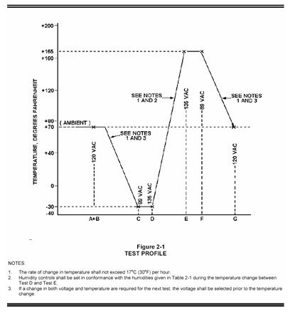
Figure 6-1 NEMA Temperature Profile
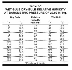
Figure 6-2. NEMA Relative Humidity Profile
Detailed operational testing is performed at room temperature, low temperature, and high temperature with varying line voltage and power interruptions. Vendors typically subject only a single unit to the testing profile, and the unit is often not continuously monitored; as a result, failures caused by thermal transients during temperature transitions can go undetected. Further, the shock and vibration testing should be performed before the functional and environmental testing. Performing the environmental testing after the shock and vibration testing should reveal any previously undetected problems due to intermittent connections or components that may have suffered damaged as a resulted of the mechanical testing.
For the environmental testing, it is recommended that the procurement specification require the vendor to develop the test plan with references to the specific environmental requirements to be verified and submit this test plan to the agency for review and approval. The rational for this approach is that the vendor can then develop the test plan based on their available instrumentation and resources. Review of the test plan and associated test procedures is extremely important. A proper review of the test plan requires that the agency (or their representative with the appropriate technical expertise) compare the specifications and additional standards with the proposed test procedures to ensure that all of the requirements are verified. Such a test plan should be submitted well in advance of the planned testing date, and it is recommended that agency personnel and/or their representatives observe the testing program.
The environmental test configuration should include a means to continuously monitor and record the operation of the device under test (DUT). The vendor should be required to develop simulators and monitoring interfaces that will continuously exercise the unit's inputs and monitor all of the unit's outputs. For devices such as traffic controllers, ramp meters, and detector monitoring stations, it is essential that strip chart recorders or similar devices be used to continuously record the operation and that inputs are "stimulated" in a known manner to verify monitoring and data collection calculations. For devices such as DMS, new messages need to be sent to the sign, and pixel testing should be periodically requested. All results should be logged. For all ITS devices, a simulated central computer system needs to continuously (at least once per minute) interrogate the device and verify the proper responses. If the device is intended to support once-per-second communications, then the central simulator should interrogate the device at that rate. All of the device inputs and outputs (e.g., auxiliary functions) must be included in the testing; where measurements are required (e.g., speed traps), the simulator must be able to provide precise inputs to the DUT to verify proper interface timing and calculations.
The test plan must include provisions to verify the test configuration before starting the test. To accomplish this, the test procedure must be reviewed to determine whether all the test conditions can be met and that the appropriate test tools (including software), test equipment, and other resources that will be used to accomplish the test are available and ready to support the test. If the test configuration cannot support the testing requirements for observing, measuring and/or recording expected results as detailed in the test procedure, then the test configuration cannot be verified and the test should not be attempted.
Constructing and configuring a test environment that establishes the appropriate set of test conditions, test stimulus, and measuring and recording equipment while remaining unaffected by the DUT can be difficult. For example, a rapid power interruption and restoration test procedure may cause the DUT to fail, shorting out its power supply and blowing a fuse on the power source side. If the test environment and DUT are fed from the same fused source, the test instrumentation and simulation equipment will also lose power and can't record the event or subsequent effects. Independent power feeds would prevent this problem and expedite testing. When reviewing test procedures, the accepting agency should pay careful attention to what is defined for the test environment and how it is isolated from the DUT.
The environmental test plan must include, as a minimum, the following elements:
- A complete description of the test environment including a diagram showing all wiring and instrumentation, the location of all equipment, etc.
- A detailed description of the techniques that will be used to measure the performance of the DUT. The test procedure should also include verification of calibration certificates for all test equipment used to measure or control temperature, voltage, vibration, shock, and timing (frequency, spectrum, etc.).
A complete step-by-step procedure (test scenarios) showing how each requirement listed in the specifications (and auxiliary standards which may be invoked) will be verified. For any measurement or printed result, the test procedure should indicate the expected (correct) result; any other result is classified as an error.
There are other requirements for the test procedure that will be discussed later; what the reader should understand is that a simple "follow the NEMA testing profile" is not sufficient. It is up to the vendor to determine how to demonstrate proper operation and how the test will be conducted and to show each step that will be taken to verify the requirement. It is up to the agency to review this material to ensure that the testing is thorough, fully verifies the requirements of the specifications, and, at a minimum, is representative of the extreme field conditions expected. Note that it was the responsibility of the specification writer to ensure that the requirements stated in the procurement specifications (and invoked standards) are representative of the field conditions; if the temperature is expected to be colder than -30° F, but the specification only mandated operation to -30° F, it is not reasonable to require that the vendor test to -50° F. If this is a real requirement, it should have been included in the specifications.
|
REAL WORLD EXAMPLE: Note the following are examples of environmental requirements that exceed NEMA requirements; if the vendor only tested to the NEMA standard, it is likely that the product was not subjected to testing for these requirements; therefore, additional testing will be required even if the product has been previously tested to the NEMA standard. Examples of additional requirements include:
|
In this case, the test procedure must be expanded to show that the equipment will meet these requirements.
6.2.4 Functionality
Functionality testing verifies that the device performs all of the specified operations listed in the requirements. Examples of operational requirements include the number of plans supported by a ramp controller, the number of events in a scheduler, the number of messages for a DMS, the number of fonts for a DMS, accuracy of speed detection algorithms, etc. Functionality includes such capabilities as display a message, change a timing plan, detect a failure, calculate ramp metering rates, and collect data.
Functionality testing will be extensive, and it is likely to be incomplete when one examines the complete "tree" of all possible combinations of operational situations. As an example, it is virtually impossible to test for all combinations of timing plan parameters (e.g., cycle, splits, offset), output configurations, phase sequences, communications anomalies, and preemption conditions for a traffic controller. Likewise for a DMS, it is very time consuming to test for all possibilities of animation, fonts, text, special characters, graphics, communications anomalies, message sequencing, and timing. Under these circumstances, one must weigh and manage the risk of having an undiscovered "bug" with the time and budget available and the likelihood that the specific combination will ever be experienced during operation of the device.
When attempting to determine what testing is important – one might consider some of the following:
- What happens when the communications is disrupted and restored?
- What happens under a fully loaded Ethernet connection? [Warning, 2070 traffic controllers have a problem with this.]
- How does the device recover from power outages of various types?
- Does it support the correct number of plans, events, fonts, etc.? This is generally checked at the limit conditions (i.e., plan 31, message 63, etc.) and should also be checked to see if it rejects a request for something outside the limits (e.g., 0 and limit +1).
- Does the device keep proper time; i.e., does it meet the timing accuracy and drift requirements of the specifications (see 6.2.5). Does it properly deal with the daylight savings time transitions?
- For a dynamic message sign, check basic text rendering, justification, character sizes, flashing timing, multi-phase message timing, scheduler operation, status monitoring, error detection, communications response times (assuming they were specified), and error handling for messages that are too long, improperly formulated, etc.
- For a traffic controller, check for basic operation, phase sequencing, plan transitions, event scheduling, preemption, and detector processing. For a traffic controller, it is likely that the agency has a specific subset of the overall functionality that is critical to its operation; the testing should be structured to test for those specific combinations of operation and features.
- There are a number of deployment issues that need to be addressed such as: Will there be three thousand of the devices deployed in the field or a dozen? Are the devices easy to access (e.g., 10 intersections along an arterial) or difficult (e.g., a dozen DMS spread over 200 miles of highway)? Because of the great number to be deployed or the difficulty of accessing geographically dispersed devices, testing must be more intense and robust to reduce the potential for site visits after deployment. After the device is deployed, any hardware modifications become expensive and easily offset testing expenses.
For the device functionality, each operational requirement needs to be addressed with a specific test case. The test cases are likely to be complex; after all it takes a considerable amount of setup to be able to test some of the functions.
Consider, for example, testing for correct transitions between daylight savings time and standard time. This requires that the controller clock be set to a date (last Sunday in October23 or first Sunday in April) and time prior to the 2:00 a.m. changeover time. The controller is then allowed to select and transition to the appropriate timing plan for that time and let the clock time advance to the 2:00 a.m. daylight savings time to standard time change point. At this point in the test, a check is made to determine whether the controller's clock time was either set back to 1:00 a.m. for the fall changeover or advanced to 3:00 a.m. for the spring changeover. The check should also confirm that appropriate plan for the new time was selected and that the new cycle length, phases, and that the transition is made to the correct offsets. Note for the fall change, when the time is set back, it is important to allow the controller's clock time to advance to (or be reset to near) 2:00 a.m. again and continue advancing without repeating the set back to 1:00 a.m. and the selection of a new timing plan. If the agency routinely includes 2 AM plan changes, then this needs to be factored into the test procedures.
It is also critical that the test environment provide simulation tools (hardware and software) to fully verify the required operations and that those tools be verified for accuracy. For devices such as detector monitoring stations and actuated controllers, it is essential that detector simulators be available to accurately simulate volumes, occupancies, speeds, vehicle length, etc. If a ramp meter is supposed to change plans based on specific traffic conditions, then the test environment must provide a method to accurately simulate the value of the traffic condition (volume, occupancy, etc.) input parameters that are specified to cause a plan change, and it must be verified that the change was to the correct plan. For incident detection algorithms, the simulation environment must be able to present a profile of input data to replicate the anticipated conditions. To simulate detector activations at a given frequency (vehicles per hour), and occupancy based on vehicle length, or to provide trap contact closures to simulate various speeds and vehicle lengths. As an example, detector inputs to a controller/ramp (contact closures) can be simulated using a Universal Serial Bus (USB) relay device interfaced to a PC running simple detector simulation test software.
As noted above, the vendor usually provides the test plan, but the agency or its representative needs to work with the vendor to make sure that the test plan is representative of the operation and complexities required for their specific application and as documented in the procurement specification. The procurement specification should provide specific guidance with respect to what features, configurations, and operations must be demonstrated during operational testing and therefore included in the test procedure. The agency has a responsibility to review the test procedure and assure that the test cases proposed cover all of the operational test requirements and are structured to be representative of both planned and future operations as detailed in the specification.
The operational test procedure should subject the DUT to bad data, improperly formed packets, and other communications errors (e.g., interruptions, packet loss) to make sure that it handles the situation in a safe and orderly manner.
If NTCIP standards are invoked in the specification and include requirements for default configuration parameters for such anomalies as power and communications outages, the test procedure should include checking that these default configuration parameters have been successfully implemented following the respective outages. Such errors should not cause the DUT to reset to an unknown configuration, halt, or perform unsafe operations. As an example, communications errors should not cause an intersection to go to a flashing condition, and attempts to store parameters that are "out of range" should return an error to the management station rather than store the bad values. Where these conditions are not addressed in the invoked standards, it may be necessary to include some additional provisions in the procurement specifications. As an example, should a traffic controller check the validity of a timing plan when it is being stored in the database or when it is "run"? If the former, the management station is alerted to the bad data and can correct the situation before it affects operation. However, if the data is not verified until it is "run," the traffic controller will not discover the error until it attempts to run the plan, causing disruption to the traffic flow. It is the responsibility of the agency to review the device standards (e.g., NEMA, CALTRANS TEES, IEEE) and the NTCIP standards (e.g., 1201, 1202, etc.) and determine if they meet their operational needs. If not, then the procurement specification must be augmented to address the differences.
The agency needs to work with the vendor to establish a test environment and test cases that will be representative of the proposed operation, including limit conditions (e.g., number of units on a line, maximum number of messages) and error conditions (power interruptions and communications disruptions).
6.2.5 Performance
Performance testing verifies that the device meets requirements that specifically relate to quantitative criteria (i.e. measurable) and apply under specific environmental conditions. Performance typically deals with timing accuracy, brightness, visibility, and the accuracy of the measurements (e.g., speed, volumes, temperature, RF levels).
The following is an example of performance testing that will test the resolve of both the agency and the vendor to accomplish, but is extremely important to assuring that the implementation performs correctly and will serve the intended purpose.
Verifying the accuracy of a traffic controller's internal clock and interval timing is one of the more difficult performance tests to perform. It is important that clock drift, clock accuracy (time-of-day) and the consistency of interval timing be verified to be compliant to the specification requirements. Controller clocks are typically synchronized (track) to the local AC power cycle zero (power line voltage) crossings and derive their basic once-a-second clock cycle from counting 60 successive zero crossings. The power company maintains the long-term accuracy of the 60-cycle frequency to within a few seconds, making it a very good clock synchronization reference. The power grid manages the addition and subtraction of cycles in a manner that ensures that there is no long-term clock drift; although the clock may wander within limits (up to 22 seconds has been observed), it will not drift beyond those limits. Testing for clock drift in the presence of short-term power interruptions requires very accurate measurements. For example, if the controller's internal clock maintenance software were to "loose" or "gain" even a single 60th of a second with each short-term power interruption (<500 milliseconds), over time the controller's clock will gradually drift from neighboring controllers that may have had a different short-term power interruption history. The resulting error or clock drift will be reflected as a timing plan offset error between adjacent signals which will compromise the green band.24 This type of error can cause serious damage to arterial progression depending on intersection spacing and speeds.
Testing for controller timing accuracy is far more difficult than simply looking for clock drift over a 24-hour period. It requires an accurate recording device that allows the comparison between the output timing of the DUT and a time reference standard that is accurate to within a few milliseconds. Testing a unit for the accuracy of its internal clock (typically specified as +0.005 percent) when power is not applied requires a reference to a national standard such as WWV or GPS. Because the AC power line can "wander" several seconds25 during any test period, it is important to account for this effect to ensure the accuracy of the clock drift measurements. Conversely, when monitoring the timing of a device connected to the AC power line, it is important that the reference used for such measurements be calibrated with or linked to the AC power line being provided to the DUT.
Again, the agency needs to work with the vendor to establish an appropriate test environment, specific test measurement and recording equipment, and test cases with well understood and agreed on pass/fail criteria that will verify the quantitative measures specified in the performance requirements.
6.2.6 Standards Conformance
TMS hardware procurement specifications typically reference a number of different device and communication protocol standards and require conformance to them. Representative standards include the NEMA TS2 and CALTRANS TEES traffic controller standards, the advanced transportation controller (ATC) standard, the NEMA TS4 standard for dynamic message signs, and the NTCIP communications standards. The device standards generally describe functionality and some physical features of the device. The NTCIP communication standards define the meaning and format of the data exchanged between the device and a management station (e.g., closed loop master controller, TMC, etc.) and for the most part do not describe the device's functionality. However, the test plan for a TMS that includes these devices and standard references that must test the data exchanged, device functionality, and physical features actually delivered. Where a delivered function, feature or data exchange is required in the procurement specification to conform to a particular standard, the verification test must include steps to confirm that conformance.
For example consider the NTICP standards. It is important that the procurement specifications include a complete description of what specific parts of NTCIP standards apply to this procurement and for what devices. Specifications that simply require that the device "shall be NTCIP compliant" are meaningless without an entire series of clarifying statements. It is important to identify the communication media (e.g., analog telephone, Ethernet, EIA-232), the transport to be supported (e.g., point-to-point or point-to-multi-point), and whether the exchanges will be handled on an IP network. In addition, the procurement specifications must identify the application level protocols to be exchanged (reference NTCIP 1103) such as simple network management protocol (SNMP), simple fixed message protocol (SFMP), and simple transportation management protocol (STMP - also described as "dynamic objects"). Finally, the procurement specifications must identify the value ranges for certain variables (e.g., the number of messages to be supported), and which (if any) optional objects are to be supported. These details are representative of the complexity of developing a proper device procurement specification that invokes the NTCIP standards. In order to ensure the interchangeability of the field devices, the agency procurement specification must fully identify all of the NTCIP objects to be supported, the value ranges, any specific optional objects, and how special or proprietary functions are defined in terms of both functionality and communications protocols. The NTCIP standards are a powerful tool for the agency and can ensure interchangeability of field devices, but only if the agency takes the time to fully identify both the functionality and the objects to support that functionality. For those about to develop their first NTCIP-oriented device procurement, it is recommended that they review NTCIP 9001, which is freely available on the NTCIP web site at www.ntcip.org.
There are a number of communications testers and software applications26 that can be used to exchange NTCIP objects with an ITS device, but there is no "generally accepted test procedure" for verifying NTCIP compliance to specific requirements. The Testing and Conformity Assessment Working Group under the NTCIP Joint Committee has produced a document, NTCIP 8007, "Testing and Conformity Assessment Documentation within NTCIP Standards Publications," to assist the NTCIP working groups in developing test plans to be included in the various NTCIP standards. However, there is no assurance that this section will be added to the standards.
There are two different views of NTCIP testing that need to be understood. Since the NTCIP standards generally only define communications objects (parameters), one group feels that NTCIP compliance testing can be performed by verifying that data packets and parameters sent to the device are properly stored and available for retrieval. The second group wants to verify full device functionality based on the exchange of the NTCIP objects. Their claim is that the only way to be sure that the device will perform as expected is to combine both requirements into the NTCIP test plan. Hence any NTCIP test plan must verify both the data exchanges and the device functionality. The latter requirement is probably the most important for any ITS deployment and should be included in any device testing program.
NTCIP compliance testing typically consists of "walking the MIB"27 to verify that the device supports all of the required data objects (and value ranges) of the NTCIP standards referenced in the procurement specification. Testing then uses individual SNMP SET and GET operations to verify that each of the parameters can be stored and retrieved, and that out of range data is rejected and the proper response occurs when it is out of range. If the device has a display, then that display should be used to verify that the parameter sent to the unit is what the unit displays on its front panel; if the unit allows the operator to store parameters, then the SNMP GET operations should be performed to verify that the data can be properly retrieved. Any errors noted while executing either of these processes means that the device does not conform to the NTCIP standard. There are a number of issues with NTCIP implementation that make this aspect of device testing very time consuming. First, while there are testers for SNMP, most of the available test devices do not handle STMP (dynamic objects), which are typically critical to low-speed communications to actuated signal controllers.28 As a result, the test environment may need to use a sample central system or extend the testers with scripts to verify these objects. Secondly, many of the vendors have created custom objects and block objects to improve the efficiency of the data transfers. Where they are used, the vendor will typically have a means for verifying them. While the new versions of the standards (e.g., 1202V2) have standardized these blocks, not all vendors will support all versions of the standards. Further, the NTCIP standard only deals with the NEMA TS2 described functionality. When the vendor adds features and functions beyond the basic NEMA standards, then the NTCIP testing must also be extended to verify the additional capabilities. With this type of "extension" (see section 7.2.1.3) comes a potential for conflicts between the standard NTCIP objects, the custom objects, and the block objects. Therefore, it is critical that the NTCIP testing verify the data exchanges using STMP, block objects, single objects, and the custom objects over all of the value ranges identified in the specifications. The vendor should create a test procedure with test cases to verify all of these issues and to demonstrate all functionality in the requirements.
In addition to simply verifying that the NTCIP objects can be exchanged with the device and that the device performs the proper "function" or reports the proper "status," there is a need to verify the performance on the communications channel. If the agency plans to use low speed communications, then there may be timing requirements for the communications response that should be added to the specifications. Such considerations may be part of the overall system design and not part of the NTCIP standards. However, these must be verified as part of the NTCIP testing. Such timing can be critical to a system deployment and will affect the number of devices attached to a communications channel.
6.2.7 Maintenance and Serviceability
For maintenance activities to be carried out effectively and efficiently, it is important that the procurement specifications include some serviceability requirements. For example, a specification might require that a technician be able to repair or replace any field-repairable (replaceable) subassembly in 10 minutes without risk of personal injury or damage to the device with the use of common hand tools only. Such a requirement is somewhat ambiguous because, for example, the definition of common hand tools must be established, expected field conditions (e.g., weather, traffic, etc.) must be defined, and even the type of training the maintenance technician must have. Once these clarifications have been established, the agency simply inspects the device and goes through the process of replacing any device that looks difficult to service. The procurement specification should specify that the serviceability tests will be done by agency technicians attempting to perform the maintenance activity following only the maintenance instructions in the vendor's written documentation. If specific training will be required to perform certain maintenance activities, these activities and training courses should be required deliverables defined in the procurement specification. Serviceability tests are an opportunity to verify required maintenance training and both the documentation (which is really part of the serviceability requirements) and the product's compliance with the serviceability requirements. Inadequate training and/or poor documentation will most likely result in the failure of serviceability testing. This can be educational for both the vendor and the agency. It may point out the need to alter the mechanical design; for example, the addition of mounting rails to support heavy rack-mounted equipment.
The fragile nature of the components should be addressed in the maintenance procedures. Examples of these considerations might include anti-static straps, module carriers, and special packaging for the individual subassemblies or replaced components. Other examples of problems that might be discovered during the serviceability testing include tolerances on mechanical assemblies and the complexity of the disassembly and re-assembly process to change a component. It is possible that the mechanical design may need to be altered with such additions as mounting rails, locating studs, or alternate fasteners due to problems with threaded mounts.
The agency technician should go through the complete replacement operation for such commonly replaceable components as matrix panels for a DMS display, power supplies, power distribution assemblies, rack assemblies, fan assemblies, filters, load switches, flashers, and shelf mounted devices.
6.3 When Should Testing Occur?
The previous section dealt with the types of testing that may be part of the hardware test program for ITS devices. This section discusses the chronology of a typical ITS hardware testing for the procurement of ITS devices. The testing program described herein is based on the procurement of a custom or new device, not previously provided to the agency, and without an extensive deployment history. Depending on the maturity of the product, not all of the test phases described below will be required. Each of the following discussions will provide some guidance on the testing required based on the maturity of the device.
6.3.1 Acceptance of Previous Tests
Although the project specifications may require a full testing program to verify compliance with the procurement specifications, the vendor (contractor) may offer to submit the results of tests performed on the device for a previous project or as part of their product development process in lieu of performing all or part of the specified tests. This typically occurs when the device specified is a standard product or has been proven on previous projects. When developing the procurement specifications, this request should be expected and special provisions should be included that allow the agency to accept or reject the previous test results based on a well-defined criteria. This criterion should state that the testing must be on the identical product and must encompass all of the testing required in the project specifications. If a vendor can truly show this to be the case, then the agency should require that the vendor submit the previous test results, all data taken, details of the testing configuration, and the details of the test plan. The agency should also insist on inspecting the actual device that was submitted to the previous testing program to verify that the design is truly the same (trust but verify).
To determine whether the previous results are relevant, one needs to ensure that the current product design is identical to the unit that was previously tested. The determination of "identical," however, can be subjective. Often vendors will modify their design or are forced to change their design to manage component obsolescence, reduce costs, simplify construction, or to meet special project requirements; however, they will still claim that the previous test results are valid. When determining if a re-test is required, one needs to determine if and how the electrical or electronic design has changed, and whether the design changes could adversely affect the characteristics of the device. This includes the following evaluations:
- Thermal characteristics of the device in terms of internal case temperature, adjacent component mounting, and location of ventilation. Could the change affect the temperature of operation of the device?
- Mechanical characteristics to determine if the changes could affect the shock and vibration response of the unit. Examples include location of connectors, component mounting, hardware changes that might cause a change in how the unit handles the mechanical stress.
- Electrical and electronic characteristics to determine if any of the changes could affect the operation of the unit under transient and power interruptions. One also needs to determine if component substitutions compromise the margin requirements contained within the project specifications.
Changes that appear to be relatively harmless could have significant consequences, and often require analysis by an experienced electrical and/or mechanical engineer to determine whether there are issues that would warrant re-testing vs. acceptance of previous test results.
In addition, the agency should not automatically accept the unit because it is on the qualified products list of another agency or State. The procuring agency needs to request and carefully review the full test procedure that was followed, the data that was collected, and the results that were observed. Examples of issues that should raise doubt as to the acceptability of the test results include:
- Anomalies that may have been observed but ignored because they only occurred "once."
- The test environment did not allow the device to be continuously monitored during all temperature transients and transitions.
- All of the tests were not preformed at all temperatures and line voltages. In other words, is there a question as to whether the testing was as thorough as your procurement specifications require.
There have also been instances where anomalies were observed during the testing, but a repeat of the specific test step did not repeat the anomaly so the device "passed" the test and was accepted. The agency should expect to review the cause of the failure (because this was a genuine failure) and determine if this is acceptable operation. Examples of areas which merit close scrutiny include power interruption testing, slowly varying line voltages, timing accuracy, and power line transients. Most ITS devices are expected to operate 24 hours per day 7 days a week without operator intervention; even very infrequent anomalies that require a machine reset or power to be cycled can create operational problems for both the agency and the public depending on the number of units deployed and the frequency of such disturbances.
|
REAL WORLD EXAMPLE: In a recent review of the test results provided by a vendor to show compliance with the NEMA TS2 environmental requirements, the test report declared successful operation. However, upon close review of the detailed test report and test results, it was evident that one of the tests had failed during the first attempt and then did not fail during a repeat of the test step. In this case, the failure occurred in the monitoring electronics causing the device to report a non-existent failure. Such intermittent problems can be difficult to track and might cause an agency to "disable" the monitoring because of false errors. If a single sample product exhibits a few anomalies during a carefully controlled test, what can be expected when a large number are deployed? Such a situation should require that the vendor conduct a full review of the design of the monitoring circuitry to determine what happened and why and modify the design to avoid such false readings in the future. |
6.3.2 Incoming Unit Testing
This is the lowest level of testing for hardware components delivered for installation. It involves a receiving inspection to verify compliance with the Contract Requirements Deliverables List and/or purchasing documentation, completeness of products and supporting documentation (operations and maintenance manuals, installation drawings and checklist were applicable), workmanship29 ; damage due to shipping; and stand-alone functionality testing if applicable. The functionality testing may include mechanical and interface testing as described below. Products found to be incomplete, of poor quality workmanship (as defined in the procurement specification) or damaged in shipment, or that did not pass applicable stand-alone functional testing should not be accepted. The agency should have the right to waive any minor receiving irregularities, such as missing documentation, mounting hardware or cabling and grant conditional delivery acceptance (if it is in the interest of the agency to do so), with final delivery acceptance subject to correction of the irregularities and completion of the unit testing within a negotiated time interval.
The agency should prepare a receiving inspection and unit test report and advise the vendor of the delivery acceptance. Hardware components that fail unit testing should be repackaged, with all other materials received, in their original (undamaged) shipping containers and returned to the vendor. If the shipping container has been torn open or shows extensive damage (crushed, water stains, etc.) it should not be accepted from the shipping agent. Note: completion of the unit testing and delivery acceptance will typically trigger the payment provisions of the procurement specification or purchase order. Once the unit has successfully passed unit testing and has achieved delivery acceptance status, it should be formally entered into the TMS equipment inventory and placed under configuration management control.
6.3.3 Interface Testing
Two types of interface testing are necessary: mechanical and electrical.
6.3.3.1. Mechanical
Mechanical interface testing involves inspection and test to ensure that the hardware component fits within specified space in an enclosure, equipment rack, etc. or on a required mounting bracket and has the required mounting points. It checks for component clearances, especially where the component moves on a mount such as a CCTV camera. It also includes checking to see that all required electrical and communications connectors are accessible, compatible with, and lineup with (or are properly keyed to) mating connectors before attempting mate testing. Mate testing ensures that connectors mate and de-mate with ease and do not have to be forced. This is not a functional interface test; it should not be performed with powered electrical or communications connections.
6.3.3.2. Electrical
Electrical interface testing is performed subsequent to successfully passing mechanical interface testing. Electrical interface testing can be initially performed in a test environment without using an actual enclosure, a rack, or the mounting mechanical interfaces. However, electrical interface testing must ultimately be completed on components installed at their operational sites. It includes applying power and exercising the communications interfaces. Testing is performed to determine required compliance with at least some level of operational functionality; i.e., power on/off switches, displays, and keypads are functional and communications can be established with the device.
6.4 Hardware Test Phases
When procuring "new" or "custom" ITS devices that have not been deployed before, it is best to require a comprehensive hardware test program to verify the design and operation of the device from conception to final site operation. Further, by participating in the testing of the device from its design through deployment, the agency becomes familiar with the design, the operation of the device, the complexity of the testing, and the complexity of the device. Depending on the contract, the agency may also be able to work with the vendor during the early phases of the project (i.e., during the submittal phase and the prototype testing) to suggest or support changes to improve the overall cost, utility, and reliability of the product.
In general, the hardware test program can be broken into six phases as described below.
- Prototype testing — generally required for "new" and custom product development but may also apply to modified product depending on the nature and complexity of the modifications. This tests the electrical, electronic, and operational conformance during the early stages of product design.
- Design approval testing (DAT) — generally required for final pre-production product testing and occurs after the prototype testing. The DAT should fully demonstrate that the ITS device conforms to all of the requirements of the specifications.
- Factory acceptance testing (FAT) — generally performs the final factory inspection and testing for an ITS device prior to shipment to the project location.
- Site testing — includes pre-installation testing, initial site acceptance testing and site integration testing. This tests for damage that may have occurred during shipment, demonstrates that the device has been properly installed and that all mechanical and electrical interfaces comply with requirements and other installed equipment at the location, and verifies the device has been integrated with the overall central system.
- Burn-in and observation period testing — generally performed for all devices. A burn-in is normally a 30 to 60 day period that a new devise is operated and monitored for proper operation. An observation period test normally begins after successful completion of the final (acceptance) test and is similar to the burn-in test except it applies to the entire system.
- Final acceptance testing — verification that all of the purchased units are functioning according to the procurement specifications after an extended period of operation. The procurement specifications should describe the time frames and requirements for final acceptance. In general, final acceptance requires that all devices be fully operational and that all deliverables (e.g., documentation, training) have been completed.
The following sections will explain the distinction between these phases and the product development cycle.
6.4.1 Prototype Testing
Prototype testing is intended to be a thorough test of the design of the device, but mechanically less stressful than the design approval testing (DAT) because it does not include the vibration and shock test procedures. The prototype testing should include full electrical and environmental testing to verify both the hardware and software design. It should also include inspection and verification of the serviceability, design requirements, and NTCIP compliance. If the prototype testing is robust and full featured, it is more likely that the DAT will be successful. Further, the prototype testing is the opportunity to verify both the ITS device and the DAT test environment.
Prototype testing is usually carried out on a single unit of each device type and takes place at either the vendor's facility or an independent testing laboratory if the vendor does not have the resources necessary for the testing at their facility. Even if they do have the resources, there are situations when an agency may require the use of an independent lab; for example, to accelerate the test schedule or when there is an overriding product safety issue.
Such a third party testing laboratory generally provides the measurement instrumentation, test chambers (temperature and humidity) and vibration and shock testing equipment that is expensive to acquire, operate and maintain. An independent testing laboratory will also have the technical expertise and experience necessary to conduct and monitor the testing, track access to the DUT, analyze the test results, produce a detailed test report, and certify the test operations that they are given the responsibility for performing. However, the laboratory is not likely to include domain expertise; hence, they will simply run the tests according to the documented test procedures and make the necessary measurements and observations. Thus, the robustness of the test procedure will determine the utility of the laboratory testing. More often, the laboratory simply provides the environmental and measurement equipment while the actual device testing is performed by the vendor.
During prototype testing (for a new product) it is assumed that the vendor may have included some "cuts and paste" modifications30 to their circuit design to correct defects or problems discovered during the early design testing. Thus, although the prototype phase must include the proposed final mechanical packaging, it is generally not required that the prototype meet all of the design and construction requirements identified in the procurement specifications such as hardware, paint color, component mounting, and printed circuit construction practices. Some of the "modifications" can have a tendency to compromise the structural integrity of the unit, hence most prototype testing does not mandate the full vibration and shock.
Under some circumstances, the agency may require that the vendor deliver a "mockup" of the proposed mechanical design to allow the agency to evaluate conformance to the serviceability requirements. An example that might warrant an early mockup is a custom traffic controller cabinet design to evaluate clearances and serviceability for equipment that will be housed in the proposed cabinet design. While such a mockup is not part of the prototype testing, it should be included in the procurement specifications if the agency feels it necessary to examine a representative product at an early stage of the design approval process.
While it has been stressed that the prototype testing should include full functional testing of the device, it is not unusual for the vendor to request that the hardware be tested with limited software functionality due to the prolonged software development cycle, changing operational requirements, and the pressures of the project schedule. Under these circumstances, the agency should proceed very cautiously as long as the hardware aspects of the product can truly be separated from the total product. There is a risk that latent problems will necessitate a change to the hardware design - which would require a complete repeat of the testing. Under these circumstances the vendor and the agency must weigh the risk of further delays to the project against the benefits of allowing the vendor to complete the hardware testing and move on toward the DAT. The risk is that in some circumstances, such as the traffic controller timing issues discussed earlier, the hardware design and the software design may be more closely coupled than is apparent. As a result, successful completion of the prototype testing (with limited software functionality) is no assurance of proper operation of the final product or completion of the DAT. It is important that such risks be understood by all involved and that the agency does not assume liability for any of the risks if design changes are necessary. Such risks could include increased cost of the testing program and delays in the completion of the project.
As an example, during the initial field deployment of a new traffic controller design, it was observed that the clocks were drifting by minutes per day; after extensive investigation it took a combination of a hardware change (in this case re-programming a logic array) and a software change to correct the situation. While the software changes were easy to effect (reload the firmware using a USB device), the changes to the logic array were more time consuming and required that each field device be disassembled to access the programming pins. These issues were not discovered during the DAT because the full controller functionality had not been complete at that time - and the decision was made to allow the vendor to progress even though not all of the required functionality had been completed.
Another related situation arises when the vendor requests to skip the prototype testing and go directly to the DAT. This can work to both the agency's and the vendor's advantage if the vendor is confident in their design and has a well developed and acceptable test environment. However, if prototype testing was required by procurement specification, a contract modification will be required to eliminate it, and the agency should carefully assess benefits it should receive in return, i.e., reduced schedule and testing costs against the risk of skipping prototype testing. When prototype testing is skipped, there is a heightened risk that a design defect will be found in the subsequent DAT, necessitating a change to the circuit design that violates one or more aspects of the specifications for construction and materials. Further, the DAT should be performed on several devices and the prototype testing is typically only performed on a single device. In general, the testing program is structured to complete the prototype first because it offers a lower risk to the vendor by allowing construction practices that are not acceptable at the DAT phase. In addition, it provides an opportunity for the agency to evaluate the testing plan and environment.
It is also possible that the vendor may fail (what the vendor considers to be) some minor aspect of the prototype testing and requests permission to go directly to the DAT phase of the project. As long as the agency understands the risk and that the risk lies with the vendor and not the agency, such requests should be considered if there is a benefit to the agency (i.e., schedule, cost) to do so and the request is contractually acceptable. Procurement specifications should limit the test period and the number of unsuccessful vendor test attempts allowed without incurring significant penalties, such as withholding progress payments, liquated damages, and canceling the contract for non-performance. The limited test period and limited number of test attempts helps to contain the agency's costs of participate in testing. Note: if the vendor is allowed to skip prototype testing or the prototype is accepted without satisfying all aspects of the required testing, any contractual remedies the agency may have included in the procurement specification to cover prototype test problems are no longer available.
6.4.2 Design Approval Testing
The design approval testing is the next stage of the device testing and is intended to verify the complete product (in final production form), including packaging is in full compliance with the specifications. Typically, if the vendor "got it right" during the prototype testing and there were no changes to the mechanical design or construction, then the DAT should be a routine exercise. The only additional testing performed at the DAT is for vibration and shock following either the NEMA or the CALTRANS procedures - depending on which was designated in the procurement specification.
For the DAT, the testing should be performed on multiple units that are randomly selected by the agency from the initial (pilot) production run of the devices. All of the testing and inspection is the same as that for the prototype, except for the addition of the vibration and shock tests that should be conducted before the start of the environmental and functional testing. Depending on the number of units being purchased, the agency may wish to insist that a minimum of two (2) and up to five (5) units be subjected to the full testing suite. For a typical procurement of 200 or more, it is recommended that a least 5 units should be tested.
The procurement specifications should reserve the right to require a repeat of the DAT if there is a change to the design or components. If changes are required, then the agency (or its consultant) needs to analyze the nature of the changes and determine if the full battery of testing is necessary or whether a subset of the original testing can be performed to verify the effects of the change. In some cases, no further retesting may be necessary.
Another issue to be addressed during the DAT is the overall integration testing and the availability of the other system components. If the field device is to be connected to a large-scale central system, then it is best to bring a portion of the central system to the DAT (or extend a communications link to the test facility) to verify the communications aspects of its operation, such as object encoding, protocol support, and performance timing. Where this is not feasible, the vendor should be required to develop and demonstrate a central system simulator that provides the data streams specified and measures the performance and response from the device.
For certain devices such as dynamic message signs, the prototype and DAT may be waived or required only for a sample system (e.g., the controller and one or two panels) because of the expense and availability of test chambers large enough to test a complete sign. This will depend on the maturity of the device, the number being purchased, and the thoroughness of the vendor's previous testing program. However, when the formal environmental testing is waived for devices such as DMS, it is recommended that the power interruption testing, transient testing, and voltage variation testing be performed for the complete DMS as part of the factory acceptance test.
Note that we have continued to stress the need to verify operation under transient power conditions. Since all of the ITS devices are expected to operate 24x7x365 without operator intervention, the goal is to ensure that typical power line anomalies do not necessitate the visit of a field technician to "reset" the device, clear a conflict monitor, or reset a circuit breaker. Such situations can compromise the integrity of the overall TMS at times when their use may be mission critical (e.g. evacuation during storms, evening rush hour during thunderstorms).
6.4.3 Factory Acceptance Testing
The factory acceptance test (FAT) is typically the final phase of vendor testing that is performed prior to shipment to the installation site (or the agency's or a contractor's warehouse). For a complete DMS, the FAT serves as the agency's primary opportunity to view and review the operation of the device for any special features, and to inspect the device for conformance to the specifications in terms of functionality, serviceability, performance, and construction (including materials). The DMS FAT should include all the elements of a device DAT except the environmental (temperature and humidity), vibration, and shock testing.
As with the prototype testing and the DAT, the vendor should provide the test procedure for the FAT. The FAT should demonstrate to the agency that the operation of the device, the quality of construction, and the continuity of all features and functions are in accordance with the specifications. If the device (or its constitute components) passed a DAT, then the FAT procedure should verify the as-built product is "identical" to the device (or components) inspected and tested during the DAT.
When the DAT was not performed for the complete device, such as a DMS, the FAT must include inspection and verification of the complete assembled device (with all its components) including those specification requirements (physical, environmental, functional and operational) that could not be verified at the DAT. A DMS will have to be disassembled after testing for shipment to the installation site. It is important to assure at the FAT, that the complete list of deliverables, including all the specified DMS components, cabling, fasteners, mounting brackets, installation checklist, drawings, manuals, etc. is verified for completeness and accuracy.
For more modest devices such as ramp controllers, traffic controllers, and ramp metering stations, the FAT inspection should include doors, gasket, backplane wiring, cable assembly, hardware (nuts and bolts), materials, and the list of deliverables such as load switches, prints, flashers, etc.
Each unit must be subjected to the FAT before being authorized for delivery. Once the FAT has been completed, the unit is deemed ready for transport to the installation site. For some devices, such as Dynamic Message signs and the first units of custom and new products, the agency should plan on attending the test and being part of the final testing and inspection procedure. For other standard devices, such as CCTV cameras, traffic controllers, data collection stations, the vendor will conduct the FAT in accordance with the procurement specification without the presence of agency personnel. The vendor should be required to provide a detailed description of the FAT procedure used; keep accurate records of test result including date, time, device serial number, and all test equipment, test data, etc. for each unit shipped; and identify the person(s) responsible for actually performing and verifying the test. While agency attendance at an FAT is not usually included for production devices, the procurement specification should require the vendor to notify the agency 10 days prior to when the tests will occur and reserve the right to attend any and all tests. Remember, the goal of the FAT is to ensure that the device has been built correctly and that all functions and interface circuits function properly and that all of the Quality Assurance requirements of the specifications have been fulfilled.
An extension to the FAT for electronic devices that is typically included in the procurement specifications (and referenced standards such as the CALTRANS TEES) requires that all devices be temperature cycled and subjected to a factory "burn-in" for a period of time (typically 100 hours). This procedure has been adopted to reduce the number of units that fail upon installation or during the first few days of operation (typically known as product infant mortality). In general, a 100-hour burn-in period is commonly specified for most electronic products; however, many vendors have been successful with less time, although there is no study showing the benefit to any specific number of hours.
6.4.4 Site Testing
Once the unit has been shipped from the factory, the remaining testing is closely related to the integration and final testing of the system. While the preceding factory based testing (prototype, DAT, FAT) will vary based on the maturity and experience with the product, the site testing should be the same for all of the levels of product maturity.
At this point, it is important to be aware of the potential issues that may involve payment terms. In many contracts, the owner pays 95 to 100 percent for the device the moment it is delivered to the job site. This payment is common with most civil works projects and is commonly called payment for "materials on hand." If the agency pays 100 percent, it looses all leverage31 if the device fails the site tests. Also note that for large items such as DMS it is an expensive proposition to take it down, repackage for shipment, and send it back to the factory. Therefore, the agency should keep sufficient funds to hold the vendor's attention and should do as much as possible to ensure that the device has the best chance of passing the on-site tests. Provisions for withhold amounts and the conditions for releasing these funds to the vendor must be clearly defined in the procurement specification or purchasing documentation.
Another word of caution with regard to the relationship of product delivery, site installation, and system integration. The agency must coordinate these activities so that ITS devices are not warehoused or installed in a non-operational state for prolonged periods (>60 days). There have been instances where DMS have been delivered to a storage yard so that the vendor could receive payment, yet site installation and system integration were more than 6 months delayed. The DMS remained in an un-powered and neglected condition such that when they were about to be site installed, they needed to be overhauled because the sign systems were not powered and hence the moisture and dirt were not managed. In at least one case, by the time the devices were installed, the vendor was out of business leaving the project in a tough situation. Knowing that this can occur and coordinating project activity to ensure that high technology devices are delivered and tested only when they can actually be used and placed into service will protect everyone and contribute to the success of the project.
For the purposes of this discussion, site testing will be broken into three sub-phases:
- Pre-installation testing.
- Initial site acceptance testing.
- Site integration testing.
The order in which and how these are managed depends on the method of procurement, the agency's facilities, and the overall program. Where a single contractor is responsible for all aspects of the system, including design, construction, and testing, these are in the most logical sequence. However, if there are multiple contractors and if the device is only one aspect of an overall ITS deployment, it may be necessary to accept the devices prior to the availability of the central system. Further, it may be necessary to accept and store the ITS device at a contractor's facility prior to site testing. Alternatively, the agency may establish an integration testing facility where all of the devices from various procurement contracts are installed, configured, tested, and burned in prior to transfer to the field.
6.4.4.1. Pre-installation testing
This phase is required to detect any damage during shipping. It is also an opportunity to fully configure an equipment package (e.g., controller) and burn it in (if not already done at the factory). The pre-installation testing is performed by the agency or its installation or integration contractor, who must receive and store the devices and integrate them with other ITS devices before installation. This type of testing may provide an opportunity to perform unit and integration testing in a controlled test environment prior to field installation. In either case, the intent is to verify that all of the equipment has been received without damage and is in accordance with the approved design (i.e., identical to the DAT-approved units). To fully verify an ITS device, a pre-installation testing and integration facility should be established by the agency or its installation and integration contractor. The pre-installation test and integration facility should include a simulation and test environment sufficient to exercise all inputs and outputs for the device and to attach to a communications connection for on-line control and monitoring.
Pre-installation testing can also provide an opportunity for the agency to fully configure the device (or full subsystem) for the anticipated field location. This approach allows the agency to verify all settings, input/output assignments, and operational features for the intended location. Some agencies and projects have established such a test facility that included environmental testing, so that the incoming units could be fully temperature cycled and monitored prior to installation.
If the purpose of the testing is to prepare to store the device, then the vendor should be consulted for recommendations on the proper procedures and environment to store the devices once their operational integrity has been verified.
6.4.4.2. Site Acceptance Test
The site acceptance testing is intended to demonstrate that the device has been properly installed and that all mechanical and electrical interfaces comply with requirements and other installed equipment at the location. This typically follows an installation checklist that includes physically mounting the device and mating with electrical and communications connections. Where necessary and appropriate, site acceptance testing can be combined with initial setup and calibration of the device for the specific installation location. Once the installation and site acceptance testing has been successfully completed, the system equipment inventory and configuration management records should be updated to show that this device (type, manufacturer, model, and serial number) was installed at this location on this date. Any switch settings, channel assignments, device addressing, cabling, calibration, etc. unique to this location should also be noted for future reference.
Prior to connecting or applying power to a newly installed device, the characteristics and configuration of the power feed (i.e., supply voltage and grounding) and circuit breakers (i.e., ground fault interrupters and proper amperage ratings) should be re-checked (these should have already been tested and accepted when they were installed). Remember, you own the device; improper or incorrect installation will void the warranty and could be hazardous. During this testing, it is necessary to verify all of the inputs and outputs for the device and the calibration of such parameters as loop placement, spacing, geographic location of the device, address codes, conflict monitoring tables, etc. It should also include verifying that connections have been properly made; e.g., the ramp metering passage detector is correctly identified and terminated and hasn't been incorrectly terminated as the demand detector. This will probably require driving a car onto the loop and verifying the controller (and system) is getting the proper input. The exact requirements will depend on the type of ITS device. All devices should be tested for their power interruption response to ensure that they recover according to specification requirements in the event of power interruptions. The importance of checking the power interruption response will become abundantly clear following the next lightening storm, particularly if it wasn't done and all initial settings and calibrations must be re-applied.
The agency should develop the test procedure and installation checklists for this testing if this installation is an extension of an existing system. If an installation or integration contractor is involved, the contractor should be required to develop this test procedure, which the agency must then review to ensure that it will verify the intended usage and compliance with the contract specifications.
6.4.4.3. Site Integration Testing
Depending on the schedule and availability of the system components (i.e., central system and communications network), once the device has been demonstrated to function properly (successful completion of the site acceptance test), it will be integrated and tested with the overall central system.
The test procedure for this aspect of device testing must include the full functional verification and performance testing with the system. This should also include failure testing to show that the device and the system recover in the event of such incidents as communications outages, communications errors, and power outages of any sort. This testing must include support for all diagnostics supported by the central system. Site integration testing should also look closely at the communications loading and establish a test configuration that will most closely simulate the fully loaded network.
The agency should construct a detailed test plan for the integration testing to show that all of the required central system functions [available for this field device] are fully operational.
6.4.5 Burn-in and Observation Period Testing
Once the device has been made operational, it should be exercised and monitored for a reasonable period of time. The project specifications establish this burn-in test period. It generally varies from 30 days to 60 days depending on the policies of the agency and typically requires that the device exhibit fault-free operation. During this period, the device should be exercised and inspected regularly following a test procedure (operational checklist) developed by the agency or the system integrator (and reviewed and approved by the agency).
An observation period is normally applied to a major subsystem or the total system. Normally it begins after successful completion of the final (acceptance) test and is similar to the burn-in test except it applies to the entire system. It should be noted that there are many variations of burn-in period, final (acceptance) testing, and observation period and the agency should think the process through thoroughly and understand the cost/risk implications.
It is important that the procurement specification defines what is meant by "fault free" operation and that the vendor clearly understands not only what is meant but also that the clock may be re-set and the testing repeated or extended if the device fails within the test period. The vendor has a huge disincentive to discover faults at this point. The procurement specification must unambiguously spell out what is acceptable and what the expected vendor response and corrective action is. It should also clearly state how the vendor has to document and respond to faults the vendor observes or that are reported to the vendor by the agency or its contractor. Typically, "faults" or failures are divided into minor and major faults, and it is important that the procurement specifications identify each and how the period of observation is extended for each. The specifications must also define how the period of observation is affected by outages unrelated to the device, such as communications outages, power outages, and central monitoring system outages. Minor failures are typically those that do not affect the utility of the device, but still represent incorrect operation. Examples might include the failure of a few pixels in a dynamic message sign or the failure of one string in an LED pixel with multiple strings. Basically, if the failure does not compromise the useful operation of the device, it might be classified as minor in nature. The agency will need to review and establish the criteria for each device type. All other failures would be considered major. The provisions that are included in the procurement specification for the observation period should be carefully reviewed as they can have a big impact on expectations, cost, and the future relationship between the agency and the vendor.
The period of observation should also be used to track such long-term requirements as time-keeping functions.
There are a number of different approaches that have been taken when adjusting the period of observation for major and minor failures. Some require that the device maintain a specific level of availability for a given number of days, while others have established a point system for each failure type and restart the period of observation once a certain point level is reached. Still others suspend the period of observation when the minor problem is detected and then continue once the failure has been corrected. Then, for major failures, the period of observation is restarted from the beginning once the failure has been corrected.
The agency must be realistic in their expectations. It is not reasonable to expect that a system with 25 DMS, 50 CCTV cameras, and 10 ramp meters will operate continuously without a failure for 60 days. Hence, a requirement that restarts the observation period each time there is a major failure will virtually ensure that the observation period is never completed. Hence, the point system is preferred and credit is given to the level of availability for the system as a whole.
6.4.6 Final Acceptance Testing
Final acceptance is a major milestone for any project. It represents full acceptance of the product by the agency and triggers final payment terms and conditions of the procurement specification. Final acceptance often marks the start of the warranty period for the ITS devices depending on the procurement specifications or purchase agreement.
The final acceptance test for devices usually takes place once all of the devices have been installed and have completed their period of observation and all other project work has been completed.
The final acceptance test should demonstrate that the device is fully operational and that it continues to function as specified in its installed environment and operational conditions, including compatible operation with other subsystems and devices. The procurement specification must clearly establish what is expected at the final acceptance test and the pass/fail criteria. The agency or its integration contractor should develop this test procedure. The same checklist used during the site installation test to verify proper operation can also be used for the final acceptance test. However, additional testing may be necessary to verify correct operation with, for example, similar devices on the same communications channel, up and downstream traffic controllers, and with other subsystems and devices that were not available or operational in previous tests. Typical procurement specifications will mandate that on the date of final acceptance, all devices must be fully operational and functioning properly. This is an ideal goal, but not realistically achievable for a system of any significant size. The procurement specification should make allowances for final acceptance of all installed and fully operational products on a certain date, with final acceptance of the remaining delivered but uninstalled products occurring in stages or as those products are installed and tested.
In summary, the expectations for final acceptance must be realistic; equipment of reasonable quality and reliability should be able to pass and it is not reasonable to expect 100 percent operation of all devices and systems over a prolonged period of time. Therefore, allowances must be made to ensure that the agency is protected, and that the vendor/contractor can have the equipment accepted.
6.5 Other Considerations for the Hardware Test Program
The preceding sections described a complete hardware test program for ITS devices based on the assumption that the device represents a custom design or new product. For most TMS projects, standard ITS devices will be specified, so the required hardware test program is usually less involved and therefore less costly. In either case, the test program needs to be developed in concert with developing the procurement specifications. The agency should consider the following recommendations when developing the test program.
If the agency determines the risk to be acceptable, develop the procurement specifications to allow acceptance of past testing for standard product oriented ITS devices (i.e., those that are listed on a QPL and have proven design and deployment history). However, since it is not known with certainty that a standard product will be furnished, the specifications need to describe the minimal level of testing desired. Therefore, there must be criteria for the prior tests and specification of what must be done if they fail the criteria.
Evidence of past testing will generally take the form of either a NEMA test report or a CALTRANS (or other State's) qualified products list status. For standard devices that will be deployed in a standard environment (i.e., not at environmental extremes), this is likely to be adequate. However, to make that determination, it is recommended that the agency request a copy of the complete test report showing the test environment, exactly what units were tested, and how the results were measured and logged. The test report should include all observations and measured results and should come from an independent testing lab, another State's testing lab, or a university testing lab. The agency should review the results and confirm that the testing demonstrated that the device was subjected to the testing required by the project specifications and that the results were acceptable. It is also important that the electrical, electronic, and mechanical design of the unit that was tested be the same as the device being proposed for your project. Any design differences require a careful review to determine if those differences could have a material effect in the overall performance of the unit you are procuring.
In the case of a device that is on another State's QPL, caution needs to be taken. The agency should insist on receiving a complete record of the test program (procedures) along with the details on the test environment and the test results. These should be evaluated for conformance to the agency's test requirements and contract specifications. Not all State laboratories fully test the product received, and, in some cases, the test procedure followed may be based on their expected usage rather than verifying the extreme conditions of the procurement specifications. Experience has shown that some QPLs may include older (or obsolete) versions of products and that the actual test process was more ad hoc based on the experience of the tester than a rigorous full feature test procedure.
If a review of the prior test procedures indicates that some of the requirements of the agency's specifications were not verified, the agency should require that the vendor conduct a subset of the testing to verify those additional requirements. Examples of extreme conditions that may not have been included in prior testing: slowly varying the AC line voltage or operation at an ambient temperature of -10° F (to verify a sub-second LCD response time requirement that may require a heater to satisfy).
| REAL WORLD EXAMPLE: During a DAT for a large-scale traffic control project, the vendor was required to perform simultaneous environmental testing on five units. During the testing, one of the units failed, requiring the DAT to be rescheduled for a later date. The failure was traced to a design defect in a device that was on the CALTRANS QPL and approved for use. Design modifications were required to correct the defect that had not been detected in previous testing. It was found that CALTRANS testing had been performed on only one unit and their test environment did not subject the unit to AC power line impulse noise while in full operation. |
For modified devices, the agency needs to review the nature of the modifications and determine how much of the testing program should be required. The most conservative approach is to mandate the full testing suite of prototype testing followed by the DAT. However, such testing is expensive for both the agency and the vendor, and may be unnecessary if the modifications do not significantly alter the basic design of the device. Examples include DMS where the only change is the number of rows and columns. In this instance, there should be no need to submit the sign to a complete re-test just because of these changes. However, changes to features such as sign color and the ventilation system could affect the thermal characteristics of the device, which is critical for LED technology. Therefore, although a complete re-test may not be necessary, a complete review of the thermal design should be conducted. It is also likely, for a DMS, that the testing was performed on a "sample" device consisting of several panels with the controller and some of the electronics. While the environmental testing would be acceptable, this does not subject the whole sign to the power interruption, transients, and varying line voltage. It is recommended that this subset of the testing program be repeated on the whole product, most likely as part of the FAT. Do not be dissuaded because the device requires a significant power source to conduct these tests. This part of the testing is intended to prove that the complete sign will not be affected by specific conditions-and there can be subtle problems when the entire sign is subjected to such testing.
For other devices such as traffic controllers, detector monitoring stations, and ramp controllers that use proven hardware, a difference in the number of load switches in the cabinet would be considered minor. As long as the full collection of devices is the same as previous test programs and as long as the previous testing was in a "fully loaded" cabinet, the testing can be accepted in lieu of a complete repeat of the prototype and DAT. However, if the vendor designs a new controller unit that uses a different processor, or changes the packaging of the controller electronics, then a complete re-test is probably warranted.
Testing is about controlling risk for both the vendor and the agency. Under ideal conditions, the ITS devices procured for a TMS will be standard products provided by vendors with a proven track record. However, in a low bid market place, the agency is required to purchase the lowest cost compliant units. A procurement specification that includes a rigorous testing program serves notice to vendors that the agency will test those units for compliance with specification requirements. Noting this, the vendor is more likely to review their design and ensure that it fully complies with the procurement specification.
6.5.1 Who Develops the Test Procedures
The issue of which party develops the test procedure has been discussed in several sections above. It is generally recommended that the vendor develop the test procedures for all phases of factory testing; i.e., from the prototype testing to the factory acceptance testing. This accomplishes two things that can improve the overall design of the device and the testing program. First, the vendor is forced to conduct a thorough and complete review of the specifications and standards when developing a test procedure to verify conformance to all of the requirements. From past experience, this has had the effect of improving the overall device reliability. Second the vendor can develop the test procedure based on their available resources. This means they can setup the test environment and base the test schedule on the availability of test chambers, test equipment and personnel. To make this happen, the agency must include requirements in the procurement specification for vendor development of test plans and procedures and for conducting the testing in their test environment. The procurement documents must also give the agency the right to require additions and modifications to the vendor prepared test plans and procedures, test environment, and approval rights. The procurement specifications must also stress that the test procedures are to be detailed, thorough and cover all aspects of the requirements. Make it clear in the procurement documents that sketchy and rough outlines for a testing program will not be acceptable.
However, once the vendor has developed the test procedure, the agency personnel must review the procedure to ensure that all aspects of the requirements are verified. It is best to require that the vendor include a requirements traceability matrix32 in their test plan to show that there is a test case for every requirement. Consider the following perspective when reviewing the test plan:
- The vendor can be required (if stated clearly in the procurement specification) to perform any test and inspection necessary to demonstrate product compliance.
- If the vendor passes the test, the agency has agreed to accept and pay for the product.
When it comes to the field or site testing, however, it is not clear who is the best party to develop the test procedures. This will largely depend on the contracting process and the expertise of the agency. However, the procurement specifications must clearly state the requirement for the test procedures themselves and that the acceptance test must demonstrate that the product meets specifications. Where an integration facility is developed, it is likely that the vendor will develop the test procedure in concert with the central system provider. The agency should establish the requirements for this testing (e.g., full configuration of signal displays, maximum number of loop detectors), and then let the contractor develop the procedures and facility. In other cases, the agency may be providing the facility and must tailor the procedures around what is available to them. In this latter case, the agency should develop the test procedure.
What is important is that the test procedure be thorough and include test cases and test steps that fully verify that the device complies with the requirements of the specifications. The level of detail will vary through the testing program where the DAT is the most rigorous and the site testing is typically only verifying that all features and functions are operational. Other sections of the guide will deal with the development of a good test procedure.
6.5.2 Cost of the Testing Program
Testing can be expensive because it generally involves travel and consultant support for the agency and laboratory facilities and personnel for the vendor. How these costs are allocated and accounted for will depend on the contract specifications and the procurement rules of the agency. The following provides some suggested considerations when developing procurement specifications.
If it is likely that the procurement specifications will result in the development of a custom device and the agency plans a full testing program, there are two aspects to the cost that can be treated separately: 1) travel expenses and 2) the agency's labor expenses.
If the agency plans to visit the vendor's facility to observe and participate in the testing, it should be noted that the travel expenses could vary greatly depending on the location of the vendor. It is likely that a week of travel (on average) will cost $1600 or more per person for travel expenses depending on the location, the amount of advance notice, and the airlines servicing the location. Some procurement specifications require that the vendor cover the travel expenses (hotel, air, and local transportation) for a specified number of agency representatives. However, this increases the cost to the vendor based on its location relative to the agency. When the revenue for the procurement of the devices is relatively small (e.g., $100K) this could have a significant impact to the vendor's bid price and is likely to place some of the vendors at a cost disadvantage. To mitigate this situation, the agency may wish to fund a limited number of factory visits internally and then only require that the vendor pay the expenses if a re-test is required due to test failure. This latter approach allows the vendor to share the risk and will not discourage more distant vendors from bidding quality devices for a project. The number of "free" tests may vary depending on the scale of the project and the complexity of the device. Simple devices should only require a single visit, while more complex, custom developments might require more than one attempt to pass the DAT since all five units must function properly.
If the costs (including travel, per diem and labor costs for the agency's personnel and the agency's consultants) are borne by the agency for a limited number of tests, this becomes an incentive to the vendor to pre-test and ensure that their test environment and devices are ready. This is especially true if the vendor knows that they will bear these agency costs for additional test attempts. Note that unless specific provisions for the agency to recover these costs are included in the procurement specification, the agency may find they have no recourse if the vendor repeatedly fails the testing, or if it is apparent that the vendor is not properly prepared or that the testing environment is not as proposed and reviewed. Of course, the final recourse is to cancel the contract (assuming such provisions are included in the specifications) but such drastic measures are seldom invoked.
In summary, it is recommended that the agency self-fund one or two rounds of the required factory or laboratory testing. However, each "visit" to the factory location counts as a test attempt. After two (or three) attempts, the vendor should be expected to bear all costs associated with additional testing. Each stage of testing is considered a separate "start" hence the vendor may be allowed one attempt to pass the prototype test, two attempts to pass the DAT, and two attempts to pass the FAT. Any additional attempts for each of these test stages would require that the contractor pay all expenses; when the vendor is expected to bear the costs, the specifications should indicate the labor rates and rules for per diem that will be employed. Note that if the agency includes the cost of consultant services to assist in the testing, these labor costs are very real so they should be dealt with in the contract specifications.
This approach shares the risk between the agency and the vendor. It is important that the test procedures provided are thorough and complete, showing the entire test environment, listing all test equipment, and detailing how the testing will be performed. The agency must review the proposed test plan and ensure that it is well documented, well designed, clearly stated and understood by all, and well planned in terms of a daily schedule of activities. The testing date should not be scheduled until the test plan has been approved.
6.5.3 Test Schedule
The procurement specifications should outline how the testing program fits into the overall project schedule. The project schedule must allow sufficient time for the agency to review the test plan (allow at least 30 calendar days for this review) and for the vendor to make corrections. The testing can be complex and lengthy. A typical test plan can easily run into several hundred pages with the inclusion of the test environment schematics, descriptions of the test software and simulation environment, and copies of the test cases, inspections, and requirements traceability check lists. The agency is likely to need maintenance, electrical engineering, and mechanical expertise to review this submittal. It is recommended that example test plans and test procedures be provided at the level of detail required by the procurement specification as part of the pre-bid vendor qualification materials or in response to the RFP. Additionally, they should be discussed again during the project "kick-off" meeting, particularly if the vendor's example test plans and procedure fall short of what was required by the procurement specification. This will serve to re-enforce the level of detail required by the procurement specification.
Because the testing will involve travel and is subject to travel industry pricing policies, testing schedules should not be set until the test plan has been approved. The project specifications should allow mutually acceptable test schedules to be set within pre-defined limits. However, once set, any adjustments by either party could be a cause to adjust the project schedule (and may result in claims by the vendor due to delays).
If the test fails or must be terminated due to environmental or equipment problems, the project specifications should require that the vendor provide a complete report as to the cause of the failure and corrective action(s) taken. The agency should establish some minimum waiting period between tests - typically the same advance notification required to schedule the initial test.
The agency should avoid the circumstance where there is a desperate need for the product, the vendor is behind schedule, and the testing and inspection finds a defect that should have been addressed during the design phase of the project. This situation can force compromises that one would not even consider earlier in the project. The best way to avoid these issues is to develop the inspection check list and test procedure very early in the project so that reviews and discussions of possible deviations can be explored before the looming deadlines with consequences of liquidated damages and project delays. For this reason, it is recommended that a project milestone of an approved test procedure be established very early in the project; if this is concurrent with the design submittals, then it is likely that these issues can be avoided.
6.6 Summary
This chapter has considered the testing requirements for a typical ITS device from a hardware perspective and outlined a testing program that should be employed in stages depending on the maturity of the product. It has offered some guidance as to the elements of a good testing program and addressed some of the issues associated with that program.
However, the testing program is dependent on the procurement specifications. The procurement specifications must establish the requirements for the contract deliverables and the testing program, determine the consequences of test failure, and identify the schedule and cost impacts to the project.
Where the vendor provides evidence of prior testing, the agency should review these previous test results and independently determine if the testing was sufficient for the immediate procurement specification. The agency should also require the vendor to prove that the product tested is the product being offered. The agency should also contact current users of the device to determine their operational experience.
Further, software (embedded firmware) is generally an integral part of the ITS device. Great care must be taken when accepting a device with software changes that have not undergone a complete re-test for all functionality and performance requirements. While the software changes are unlikely to affect the environmental performance of the unit, any change could have unforeseen consequences and may warrant re-testing the unit. The requirement to re-test the unit subsequent to a software change should be clearly stated in the procurement specification.
Finally, testing can be expensive for all parties; the agency must weigh the risks associated with the use of the device and the device's track record before undertaking a complete test program. If the device is of a new design or custom to the agency, then the full testing program is warranted. On the other hand, if the agency is only purchasing a few standard devices for routine field deployment and the device has already been tested according to the NEMA testing profile or is on a specified QPL, the risk is relatively low.
A word of caution: there is no "NEMA certification" for ITS devices. The term "certification" should not be used by any vendor to claim that their ITS device is NEMA certified. NEMA TS2 (and also TS4) present a test procedure and environmental requirements (electrical, temperature, humidity, shock, vibration) and describe what is expected during the test. Vendors must construct a test environment for the device application (e.g., a lamp panel, detector inputs, central communications tester) that can demonstrate the operation of the unit, and then submit the unit to an independent testing laboratory to actually perform and monitor the testing. The independent testing laboratory typically provides the temperature and humidity chambers and instrumentation for monitoring both the DUT and the test environment and provides a certification as to the authenticity of the testing and the logged results. However, it is up to the vendor to instruct the testing laboratory in how to operate the equipment and how to determine "proper" operation. The testing laboratory simply certifies that they measured and observed the recorded results. NEMA does not certify products.
17 Many states other than California and New York have developed or adopted similar standards. These, however, are the ones most often cited in the ITS industry.
18 The California Department of Transportation (CALTRANS) published a standard for Transportation Equipment Electrical Specifications (TEES); this is generally available on the CALTRANS web site: http://www.dot.ca.gov/hq/esc/ttsb/electrical/2070c.htm for the 2070. It is likely that this web link may change over time; it is suggested that a search engine be used with the search criteria of "TEES" "CALTRANS" and that the current version be located in this manner.
19 This may be very difficult to verify; one needs to review the expected life of the components and ensure that all devices used are rated for continuous 24 hours per day 7 days a week operation over a minimum of 10 years without replacement. Components such as fans - which may be extensively used in a dynamic message sign, must be rated for such continuous operation; typically the vendor is required to show that they have met this requirement by presenting component information to verify the expected life.
20 Note that most procurement specifications will also invoke NEMA TS2-2004, TS4, CALTRANS TEES or other recognized standards for the ITS device. When developing a checklist or inspecting the device for conformance, these standards must also be considered and the various requirements of those standards must be included in the checklists used for the inspections/testing.
21 Table 2-1 and figure 2-1 shown here are taken with permission from the NEMA TS2-2003 standard for Traffic Controller Assemblies with NTCIP Requirements, Version 02.06 - contract www.nema.org to purchase a full copy of this standard.
22 Note that most standard ITS devices with LCD displays do not meet this requirement since the basic standards do require support for these extremes; this requirement means that the vendor must add heaters and heater control circuitry to their product. However, if field maintenance under these conditions is expected, then such a requirement should be considered.
23 Congress has recently changed the law adding 2 weeks to daylight savings time, so in the fall of 2007 the return to standard time will occur at 2:00 a.m. on the 2nd Sunday in November.
24 The green-band is determined by the time offset between the start of the green interval at successive intersections, the duration of the green intervals at successive intersections, and the desired traffic progression speed.
25 The three continental United States power grids (Eastern, Western and Texas) are controlled such that there is no long-term "drift" for devices using the AC power line for time keeping purposes within a grid network. However, the AC power line does wander short-term by several seconds depending on the loading on the network, network disturbances, and switching. The instantaneous offset or deviation of a power grid from a WWV reference can be determined by contacting a regional WWV reliability coordinator. http://tf.nist.gov/timefreq/stations/wwv.html
26 See NTCIP 9012.
27 Management information base that lists all of the SNMP objects supported by the device. This is a series of GET NEXT commands until all objects have been retrieved.
28 STMP is not generally supported by most ITS devices; STMP allows the efficient exchange of dynamically configured data which is essential to supporting once per second status monitoring. Devices such as DMS and ESS generally don't need this type of high-speed communications and therefore may not support STMP.
29 Judging quality workmanship is very subjective particularly if no definition or qualifiers are included. Specific criteria for workmanship such as no burrs or sharp edges; freedom from defects, and foreign mater; and product uniformity, and general appearance should be included. They are applicable when the skill of the craftsman or manufacturing technique is an important aspect of the product and its suitability for the intended use. However, since there are no definite tests for these criteria, verification is by visual inspection.
30 "Cut and paste" refer to a practice used by vendors to modify an existing circuit board's electronic design and layout by bypassing existing copper lands used to connect the board's components or external connectors. Under proper conditions each component is mounted directly to the circuit board, and all circuit lands are properly routed to the components and connectors. However, when a design problem is discovered, the vendor may correct the problem by simply gluing a new component to the circuit board, cutting existing leads, and running small wires (jumpers) to connect the new component to the proper points in the circuit. When such "modifications" are complete, the circuit reflects the final design, but the construction practices are generally considered unacceptable (particularly for a production product). If the circuit modifications are for relatively low-speed sections of the design, such cuts and pastes are not likely to affect operation; however, for high-speed designs (e.g., 100 Mbps Ethernet) such modifications could compromise the operation of the circuit. Such repairs are typically allowed at the discretion of the accepting agency for a prototype, or for very low number (pilot) production runs and with the understanding that the next production run will not include such modifications and previously accepted products will be replaced at the vendors cost with new products from that production run.
31 Except recourse to the bonding company where a bond is in place.
32 The requirements traceability matrix lists each of the requirements to be verified by the test in a matrix format. It includes for each requirement: the requirement's source reference paragraph no., the requirement statement from source specification; and provides the test method, test case no., and test responsibility for verifying the requirement.