Regional ITS Architecture Guidance Document
Regional ITS Architecture Guidance Document
 Once
an ITS project has been funded and implementation begins, there is a natural
tendency to focus on the programmatic and technical details of the project to
be implemented and lose sight of the broader regional context for the project.
Using the regional ITS architecture as a basis for project implementation
provides this regional context. It provides each project sponsor the
opportunity to view their project in the context of surrounding systems. It
prompts the sponsor to think about how their project fits within the overall
transportation vision for the region. It identifies the integration
opportunities that should be considered and provides a head start for the
systems engineering analysis that is required for ITS projects.
Once
an ITS project has been funded and implementation begins, there is a natural
tendency to focus on the programmatic and technical details of the project to
be implemented and lose sight of the broader regional context for the project.
Using the regional ITS architecture as a basis for project implementation
provides this regional context. It provides each project sponsor the
opportunity to view their project in the context of surrounding systems. It
prompts the sponsor to think about how their project fits within the overall
transportation vision for the region. It identifies the integration
opportunities that should be considered and provides a head start for the
systems engineering analysis that is required for ITS projects.
 Due to these potential benefits, the
Rule/Policy requires the regional ITS architecture to be used for project
implementation. Specifically, FHWA Rule 940.11.c.1 and FTA National ITS
Architecture Policy Section 6.c.1 require identification of the portion of the
regional ITS architecture that is implemented by each ITS project.
Due to these potential benefits, the
Rule/Policy requires the regional ITS architecture to be used for project
implementation. Specifically, FHWA Rule 940.11.c.1 and FTA National ITS
Architecture Policy Section 6.c.1 require identification of the portion of the
regional ITS architecture that is implemented by each ITS project.
As described in previous sections, transportation projects are identified and funded through transportation planning and programming/budgeting phases. Funded projects are then implemented using a project development process that will vary with the type of project. For example, ITS projects that install field equipment (e.g., installation of variable message signs) use a process that is very close to the traditional project development process shown in Figure 41. ITS projects that include hardware and software development and integration will require additional systems engineering analyses that can be thought of as extensions to the traditional project development process.
Figure 41: Using the ITS Architecture in Project Implementation
While project development processes vary from state to state and from organization to organization in each state, the transportation project development process tends to have the same major steps.
As shown, the best opportunity for use of the regional ITS architecture is early in the development process when the project is initiated and preliminary engineering is performed. The architecture is most valuable as a scoping tool that allows a project to be broadly defined and shown in a regional context. In later steps, when the project scope is firmly established and the project is defined in increasing detail, there is less opportunity to use the high-level definitions included in the regional ITS architecture. More detailed guidance for using the regional ITS architecture at each step in the project development process is defined later in this section.
Project Development Roles
There are several distinct roles to consider when developing an approach for architecture use in your region. These roles include:
Architecture Use Challenges and Solutions
Regions must address a few challenges if the regional ITS architecture is to be used effectively to support project development. Across the country, regions are each encountering the same challenges and best practices are beginning to emerge that will encourage beneficial use of the architecture. Six challenges and their corresponding solutions are described below.

Solution: If it is to be used, the regional ITS architecture must be readily available to all Project Sponsors in the region. The latest version of the architecture should be available in a location readily accessible to all Project Team members. An architecture web page that provides access to the latest architecture information and resources is ideal. The form of the regional ITS architecture documentation should allow easy cut-and-paste into project documentation.
Solution: The points at which the architecture should be used in project development should be formally documented for the state or region. In particular, an early checkpoint should be identified where the Project Team should have considered the architecture as the project scope is established so that integration opportunities are considered for each ITS project. A later checkpoint should be established where the Project Team should have verified that the as-designed project is consistent with the architecture and identified any regional ITS architecture changes that would be required to achieve this consistency.
 The FHWA/FTA Division
Office should play a leading role in defining these points in the process,
integrating architecture use requirements with existing federal oversight
requirements. Such top-down inclusion is the only way to ensure systematic
architecture use by all Project Sponsors in the region.
The FHWA/FTA Division
Office should play a leading role in defining these points in the process,
integrating architecture use requirements with existing federal oversight
requirements. Such top-down inclusion is the only way to ensure systematic
architecture use by all Project Sponsors in the region.
Solution: Although not everyone will be an architecture expert, at least one member of every Project Team must be able to effectively use the architecture. If the Project Team does not have this expertise, then technical assistance must be provided by the Architecture Maintainer, FHWA/FTA Division office, or another resource to identify the relevant portion of the architecture for the project. To facilitate architecture use, the region should make the architecture as easy to use as possible, document instructions for use in project implementation, and make technical assistance and training available to Project Teams.
 The
architecture should be supported by a roadmap for architecture use that can be
used by each Project Team. The roadmap for architecture use includes
step-by-step instructions for how the region's architecture
documentation should be used for project development.
The
architecture should be supported by a roadmap for architecture use that can be
used by each Project Team. The roadmap for architecture use includes
step-by-step instructions for how the region's architecture
documentation should be used for project development. Ease of use should be
coupled with an effective technical assistance program that allows Project
Teams to get the assistance that they need when they have a question about
architecture use. As technical assistance is requested and provided, it is a
good idea to continue to enhance the documentation available to every Project
Team with a set of frequently asked questions and answers that can further
facilitate future use.
Ease of use should be
coupled with an effective technical assistance program that allows Project
Teams to get the assistance that they need when they have a question about
architecture use. As technical assistance is requested and provided, it is a
good idea to continue to enhance the documentation available to every Project
Team with a set of frequently asked questions and answers that can further
facilitate future use.
Figure 42: Architecture and Location-Specific Projects
Solution: In order to effectively use the architecture, the Project Team must bridge the gap between the higher-level regional ITS architecture and the relatively specific definition of a particular project. The different levels of abstraction are a potential stumbling block that should be addressed in the region's guidance for architecture use. For example, the project block diagram in a concept of operations may be more specific than what is represented in the regional ITS architecture, but still traceable to the regional ITS architecture. While it is sometimes beneficial, you should
proceed with caution when adding detail to your regional ITS architecture so
that it more precisely depicts individual projects. For example, a city may
deploy field equipment with ten different projects over the course of several
years. It is probably a mistake to include ten different inventory elements in
the regional ITS architecture that specifically represent the equipment in each
anticipated project. This would add too much detail to the regional ITS architecture
and make it more difficult to maintain.
While it is sometimes beneficial, you should
proceed with caution when adding detail to your regional ITS architecture so
that it more precisely depicts individual projects. For example, a city may
deploy field equipment with ten different projects over the course of several
years. It is probably a mistake to include ten different inventory elements in
the regional ITS architecture that specifically represent the equipment in each
anticipated project. This would add too much detail to the regional ITS architecture
and make it more difficult to maintain.
Solution: Information on the benefits of architecture use should be available to every project sponsor, not only those who sponsor projects that use the Highway Trust Fund. Some agencies, such as Virginia DOT, have developed a user guide that encourages architecture use for ITS projects, whether or not Highway Trust Funds are used. To coordinate public safety projects, SANDAG, the San Diego MPO, has established a public safety committee that coordinates planning for public safety integration projects with SANDAG. The architecture maintenance activity should periodically update the architecture to reflect other ITS projects that have been implemented so that the architecture continues to accurately reflect ITS implementation in the region.
Solution: The purpose of the architecture use and systems engineering analysis requirements for ITS projects is to reduce technical risk and increase the likelihood of project success. Since the inherent risk in an ITS project varies significantly depending on the nature of the project, the Rule/Policy allows the systems engineering analysis to be tailored commensurate with project scope. Projects that will benefit most from architecture use include:
Projects that are inherently limited in scope will benefit less from architecture use, such as:
There is some potential benefit from architecture use on even the simplest ITS projects. For example, signal synchronization projects may benefit from architecture use in regions where integration of adjacent traffic signal systems is planned. The FHWA/FTA Division Office determines how the Rule/Policy should be applied to different types of ITS projects in the region. For example, the California Division Office has established oversight procedures that require architecture use for all ITS projects, but only require direct oversight for higher risk "major" ITS projects. Some regions have established graduated processes where more detailed architecture use is suggested for more complex projects. For example, Virginia DOT has established guidelines for architecture use that require project architectures for more complex projects that include more than three stakeholders. An early project initiation checkpoint should include information about the project that allows project type and complexity to be determined so appropriate architecture use and systems engineering analysis processes can be defined.
The regional ITS architecture provides a starting point for systems engineering analyses that are performed during ITS project development. Systems engineering is an interdisciplinary approach for systems development that is used in many different industries because it contributes to project success. Every ITS project manager wants a successful project, where "success" is measured by:
The primary benefit of systems engineering is that it will reduce the risk of schedule and cost overruns and increase the likelihood that the system will meet the user's needs. Other frequently cited benefits include:
Figure 43 is a systems engineering "V" model that graphically depicts the systems engineering approach. The core systems engineering project development processes that are the focus of this section are enclosed in a dashed box at the center of the "V".
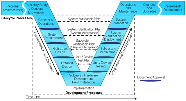
Figure 43: Systems Engineering Approach
The "V" diagram also includes two wings that show the broader project lifecycle from initial project identification at the beginning of the lifecycle through system retirement or replacement at the end of the lifecycle. An important aspect of the systems engineering process is that the entire project lifecycle is considered during project development.
A systems engineering approach requires up-front planning and system definition so that the project requirements are identified and documented, before technology choices are made and the system is implemented. On the left side of the diagram, the system definition progresses from a general user view of the system to a detailed specification of the system design. As development progresses, a series of documented baselines are established that support the following steps. For example, a consensus concept of operations supports system requirements development. A baseline set of system requirements then supports system design. The hardware and software are implemented during coding and fabrication shown at the bottom of the diagram, and then the components of the system are integrated, tested, and verified in iterative fashion on the right. Ultimately, the completed system is validated to measure how well it meets the user's needs. Significantly, there is traceability from one step to the next and also traceability between steps on both sides of the diagram since the system definition that is generated on the left is used to verify the system on the right. The user needs that are identified in the very first step of the process are used to validate the completed system as part of system validation.
In addition to the process steps identified in the "V", there are several cross-cutting activities that contribute to successful projects. Development of a systems engineering management plan (SEMP), configuration management, risk management, and project monitoring and control are all best practices that are associated with systems engineering that will benefit ITS projects.
 Following a system engineering approach
during implementation of ITS projects is a key requirement of the Rule/Policy.
However, providing guidance for systems engineering is beyond the scope of this
document. For additional resources or training on system engineering, refer to
the ITS Resource guide, (http://www.resourceguide.its.dot.gov/),
the NHI website (http://www.nhi.fhwa.dot.gov/),
or the International Council on Systems Engineering (INCOSE) website (http://www.incose.org) for more information.
In addition to these national systems engineering resources, several states
have developed systems engineering guidance for ITS projects including the Systems
Engineering Guidebook for ITS, created by the FHWA California Division and
Caltrans (http://www.dot.ca.gov/research/se_guidebook_ver1-12_14_05.pdf)
and the Florida DOT Systems Engineering Management Plan (http://www.dot.state.fl.us/TrafficOperations/ITS/Projects_Deploy/SEMP.htm).
Following a system engineering approach
during implementation of ITS projects is a key requirement of the Rule/Policy.
However, providing guidance for systems engineering is beyond the scope of this
document. For additional resources or training on system engineering, refer to
the ITS Resource guide, (http://www.resourceguide.its.dot.gov/),
the NHI website (http://www.nhi.fhwa.dot.gov/),
or the International Council on Systems Engineering (INCOSE) website (http://www.incose.org) for more information.
In addition to these national systems engineering resources, several states
have developed systems engineering guidance for ITS projects including the Systems
Engineering Guidebook for ITS, created by the FHWA California Division and
Caltrans (http://www.dot.ca.gov/research/se_guidebook_ver1-12_14_05.pdf)
and the Florida DOT Systems Engineering Management Plan (http://www.dot.state.fl.us/TrafficOperations/ITS/Projects_Deploy/SEMP.htm).
Systems Engineering and the Traditional Project Development Process
As it evolved through a century of building roads and public transit systems, the transportation project delivery process used by most agencies today already includes many important features of the systems engineering process. In both processes, the system is specified in increasing detail, beginning with needs, moving to requirements, and then into design. Multi-disciplinary project teams and systematic stakeholder outreach and communications are hallmarks of a good transportation project development process and good systems engineering practice. By taking advantage of these similar concepts and processes, the systems engineering process can be integrated as an extension to the agency's existing project development process. This alignment of the traditional transportation project development process and the systems engineering process is shown in Figure 44.
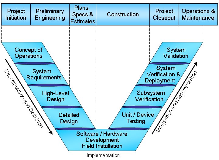
Figure 44: Systems Engineering and Traditional Project Development
Making these types of linkages and mainstreaming ITS development into the agencies' project development process makes it easier to incorporate the regional ITS architecture as a tool in each agencies' process.
The project development process is also influenced by the selected procurement strategy. ITS projects have been procured through traditional low bid, systems manager, design/build, task order, and other innovative procurement approaches. The procurement strategy will influence who (agency, consultant, or contractor) takes the lead for each process step, but the fundamental systems engineering process steps (Concept of Operations, Requirements, Design,...) should still be accomplished for all types of ITS procurements.
For additional resources or training on ITS
procurement, refer to the ITS Resource guide, (http://www.its.dot.gov/itsweb/guide.htm)
or the NHI website: http://www.nhi.fhwa.dot.gov/
for more information.
Rule/Policy Systems Engineering Analysis Requirements
 US DOT recognized the potential benefit of a systems engineering
approach and included requirements for a systems engineering analysis for ITS
projects in the FHWA Rule/FTA Policy. The Rule/Policy requires a system
engineering analysis to be performed for ITS projects that are funded through
the highway trust fund. As shown in Figure 45, the Rule/Policy specifies
seven requirements that the systems engineering analysis must include at a
minimum. The systems engineering analysis requirements in the Rule/Policy
focus on the first few steps of the systems engineering approach. The
regional ITS architecture can be used to support the Rule/Policy requirements
as well as the broader systems engineering approach that is recommended for ITS
projects.
US DOT recognized the potential benefit of a systems engineering
approach and included requirements for a systems engineering analysis for ITS
projects in the FHWA Rule/FTA Policy. The Rule/Policy requires a system
engineering analysis to be performed for ITS projects that are funded through
the highway trust fund. As shown in Figure 45, the Rule/Policy specifies
seven requirements that the systems engineering analysis must include at a
minimum. The systems engineering analysis requirements in the Rule/Policy
focus on the first few steps of the systems engineering approach. The
regional ITS architecture can be used to support the Rule/Policy requirements
as well as the broader systems engineering approach that is recommended for ITS
projects.
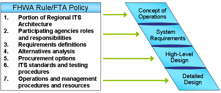
Figure 45: Rule/Policy Systems Engineering Analysis Requirements
Good systems engineering practice goes beyond the seven requirements in the Rule/Policy. Systems engineering is a systematic approach for defining, building, and validating systems that satisfy customer needs as described earlier in this section. A complete systems engineering approach also addresses planning, risk management, configuration management and other processes. Each Project Sponsor should use a systems engineering approach that can be tailored to fit the needs of a specific ITS project. The required systems engineering analyses identified in the Rule/Policy become "required" steps that cannot be tailored out.
The complete systems engineering
analysis required for ITS projects is defined in FHWA Rule 940.11 and FTA
National ITS Architecture Policy Section 6.
Sections 7.3.4 through 7.3.7 walk through the opportunities for using the information in a regional ITS architecture to support the steps in the systems engineering process. Each opportunity for architecture use is described in the order that it would occur during project development, as shown in Figure 46.
Before the regional ITS architecture can be used, the portion of the architecture that is relevant to the project must be identified. The process of identifying the subset of the regional ITS architecture is described in section 7.3.4. Once the relevant portion is identified, the relevant components can be used to support the systems engineering process. The potential use of the regional ITS architecture to support each of the early process steps is described in sections 7.3.5 through 7.3.7.
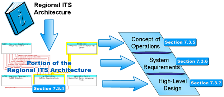
Figure 46: Using the Architecture to Support Systems Engineering
Since every regional ITS architecture is a bit different, each architecture's utility in supporting the systems engineering process will vary. For example, regional ITS architectures that include tailored functional requirements will provide a better starting point for project system requirements definition than regional ITS architectures that have fewer generic requirements. The region should take a candid look at the utility of their regional ITS architecture in the project implementation process and refine it over time so that it provides the best possible support for each project sponsor's systems engineering process.
In order to use the regional ITS architecture to support project development, the portion of the regional ITS architecture that will be included in the project must be identified. This is a key step in architecture use because this is when the ITS project will be viewed in the broader context of the regional ITS architecture. This is when the services, functionality, and integration opportunities envisioned in the region are reviewed and considered as the basic scope of the project is defined. This step is also required to meet the FHWA Rule/FTA Policy. While the components that should be identified as part of this "subset" are not specified by the Rule/Policy, the following components, taken together, precisely define the scope of the project in terms of the regional ITS architecture:
These three components define the system(s) that will be created or impacted by the project, the functionality that will be implemented, and the interfaces that will be added or updated.
If integration opportunities are to be considered, the regional ITS architecture should be used as early in the project development lifecycle as possible. The architecture should be reviewed before firm project cost estimates are established, while there is still opportunity to adjust the scope to accommodate the functionality and interfaces identified in the regional ITS architecture. This opportunity may occur before or after programming/budgeting, depending on how specifically the ITS project is defined in the TIP/STIP or other programming/budget document.
Finding the Right Components
It can be difficult to find the components that apply to a project, particularly if the Project Team is unfamiliar with the regional ITS architecture. The best approach for identifying the portion of the regional ITS architecture for a particular project will vary since each regional ITS architecture is defined a bit differently. There are a few logical entry points to the regional ITS architecture that may be of use to the Project Team — chances are that one of these approaches will work best in your region.
Start with Transportation Services
Transportation services, which are typically represented as market packages, are an excellent way to begin to isolate the portion of the regional ITS architecture that may apply. By identifying the service that the project performs and finding this service in the list of market packages included in the regional ITS architecture, the portions of the architecture related to that service can be identified and then tailored for the project. Note that in most cases, the market package will have to be further refined to precisely match the scope of the project.
Start with Project Sequencing
The connection between the regional ITS architecture and ITS projects is clearest if the project to be implemented is identified in the project sequencing portion of the regional ITS architecture documentation. If the project is identified and explicitly related to the regional ITS architecture in the project sequencing section, then this is probably the best entry point for the Project Team to use. If the project is not included in the project sequencing documentation, then feedback should be provided to the Architecture Owner so that the architecture can be updated to reflect the range of projects that are actually being implemented in the region.
Other Starting Points
Depending on the architecture documentation, the Project Team could locate the target system(s) in the list of inventory elements or identify the stakeholder(s) associated with the project in the list of stakeholders. Depending on the linkages in the architecture documentation, one of these entry points can be used to find the portion of the regional ITS architecture that is most relevant to the project to be implemented.
 In order to facilitate use by numerous Project
Teams, each region should define a roadmap for architecture use that takes
advantage of the strengths of their specific regional ITS architecture. The
roadmap should identify the best entry point(s) (e.g., Market Packages, Project
Sequencing, Inventory Elements, etc.) for that architecture, how to locate the
relevant item in the list, and how to navigate to other related items in the
architecture documentation.
In order to facilitate use by numerous Project
Teams, each region should define a roadmap for architecture use that takes
advantage of the strengths of their specific regional ITS architecture. The
roadmap should identify the best entry point(s) (e.g., Market Packages, Project
Sequencing, Inventory Elements, etc.) for that architecture, how to locate the
relevant item in the list, and how to navigate to other related items in the
architecture documentation.
Considering Additional Integration Options
In almost every case, the regional ITS architecture will identify integration opportunities that will not be included in the current project. Integration options may be deferred for many reasons — agencies on both sides of the interface may not be ready, there may not be sufficient funding or time available to implement everything, supporting infrastructure may not yet be completed, a necessary standard may not be available, implementing too much at once may incur too much complexity/risk, etc.
It is important to explore these integration opportunities so that they are accounted for and supported in the project design, even though they may not be implemented with that specific project. The ultimate goal is to make ITS deployment as economical as possible by considering how this project will support future projects over time. To support this goal, future integration options that may impact the project design should be identified and considered in the project development. For example, additional stakeholders may be involved in the current project to ensure that future requirements are identified and factored into the current project design.
Example Output
The subset of the regional ITS architecture that is included in the project can be shown in a series of simple tables or a diagram from Turbo Architecture, as shown in Figure 47. This figure identifies the inventory elements and interfaces that will be implemented by the Maine DMS project. Functional requirements that are relevant to the project would also be extracted. A subset of these requirements are shown later in this chapter, in Table 15.
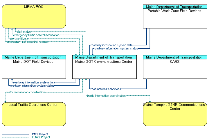
Figure 47: Example Maine DMS Project Architecture Subset
As shown in the figure, the DMS project will include both portable and fixed dynamic message signs (represented as field devices in the regional ITS architecture), control software in the MaineDOT Communications Center, and an interface to the Condition Acquisition and Reporting System (CARS) so that sign information can be distributed as traveler information. Future interfaces that are related to DMS operation from the regional ITS architecture including coordination with local cities to coordinate traffic diversions, coordination with the MEMA EOC to support use of the signs in emergencies, and coordination with the Maine Turnpike are also included in the diagram for context, although they are not included in this project.
It is a good idea to include additional
interfaces that are closely related to the project, as shown in the previous
example. This gives some context for the project and conveys information to
the project team about how this project will fit with other future projects.
Where this is done, the documentation should be clear about the subset that is
actually included in the current project. It is also important not to include
too much additional information — the goal is to include only components that
are in some way relevant to this particular project, particularly those that
may influence project design decisions.
 If Turbo is used, then a project ITS
architecture can be specified that collects together all the relevant portions
of the architecture for that project. See the Turbo Architecture User's Manual
and Turbo Architecture training course that is offered through the National
Highway Institute (http://www.nhi.fhwa.dot.gov/)
for more information.
If Turbo is used, then a project ITS
architecture can be specified that collects together all the relevant portions
of the architecture for that project. See the Turbo Architecture User's Manual
and Turbo Architecture training course that is offered through the National
Highway Institute (http://www.nhi.fhwa.dot.gov/)
for more information.
A well-defined regional ITS architecture provides a good starting point for developing a concept of operations (ConOps) for an ITS project. The purpose of the ConOps is to clearly convey a high-level view of the project to be developed that each project stakeholder can understand. The components of the regional ITS architecture provide a high-level description of the ITS systems in the region, which can often be directly incorporated into a project ConOps. Several of the regional ITS architecture components can be used, as shown in Figure 48, which relates the regional architecture to a typical outline for a ConOps based on the industry standard, ANSI/AIAA G-043-1992. The ConOps for an ITS project should include this information and many more details specific to the project as described in the following paragraphs.

Figure 48: Architecture Use for Concept of Operations
Stakeholder Identification
A ConOps should describe the system from the perspective of each stakeholder. The relevant stakeholders that are identified in the regional ITS architecture are a good starting point for the list of stakeholders considered in the ConOps. The Project Team may need to add stakeholders or provide additional specificity for selected stakeholders. For example, in the Maine DMS Project, the "MaineDOT" stakeholder identified in the regional ITS architecture is further distinguished into separate MaineDOT divisions — Planning, Maintenance and Operations, and Information Services because each MaineDOT division has a distinct role in the project.
Operational Concept
The agency roles and responsibilities that are specified in the ConOps can be derived from the operational concept that is included in the regional ITS architecture. This operational concept can serve as a starting point for a more detailed definition of the operational roles that are described in the ITS Project ConOps.
The specification of participating agencies' roles and responsibilities is a required part of the Systems Engineering Analysis as specified in the Rule/Policy.
Functional Requirements
The high-level functional requirements that are defined in the regional ITS architecture are frequently defined at a level that is commensurate with the operational needs that should be defined in the ConOps. The operational needs that are defined in the ConOps then provide a basis for the project requirements that are defined later in the systems engineering process. The high-level requirements from the regional ITS architecture can be included in the ConOps and modified and expanded as necessary so they represent the operational needs of the specific project.
Interfaces / Information Flows
The ConOps includes a high-level project description that is normally supported by a high-level system block diagram. This system description can be based on the interfaces and information flows that are extracted from the regional ITS architecture. Depending on the regional ITS architecture and the nature of the project, the project description that is derived from the regional ITS architecture should be refined so that it is as easy to understand as possible in the ConOps. For example, Figure 49 is a block diagram for the example Maine DMS project that is derived from the regional ITS architecture diagram in Figure 47, but it is specifically focused on the DMS project (e.g., "DMS" is used rather than "Field Equipment" and controllers that are hidden in the regional ITS architecture are shown).
Figure 49: DMS Project Example Diagram
The relationship to the regional ITS architecture that is developed for each project (see paragraph 7.3.3) should also be included in the ConOps. If the ANSI/AIAA outline is used for the ConOps, this information would logically fit in the Operational Environment paragraph, or the outline could be tailored and a specific "Relationship to the Regional ITS Architecture" paragraph could be added.
Agreements
System integration is as much an institutional challenge as it is a technical systems engineering exercise. The regional ITS architecture identifies regional agreements that may be relevant to the project. Necessary agreements should be identified for the project and listed in either the project plan or the ConOps. If the ANSI/AIAA outline is used, the list of agreements would logically fit in either the operational environment or support environment sections. The location of the list of agreements isn't so important as long as it is included in the document and the project plan addresses the creation of the necessary agreements. If necessary agreements are not represented in the regional ITS architecture, feedback should be provided to the Architecture Maintainer.
The functional requirements and interfaces defined in the regional ITS architecture can be used to support system requirements definition as shown in Figure 50. The functional requirements associated with the inventory element(s) that are included in the project can be scanned to identify requirements that cover the required functionality for the project. These functional requirements can be one of the inputs to system requirements definition. In addition to the functional requirements, the project interfaces that are identified in the regional ITS architecture should also be supported by system requirements associated with each interface.
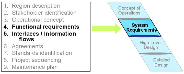
Figure 50: Architecture Use in System Requirements Development
Of course, the project's system requirements should be defined in greater detail than the high-level functional requirements that are included in the regional ITS architecture. The system requirements should also address performance, development, operations and maintenance, and other requirements that are typically not included in a regional ITS architecture as shown in Figure 51. While the requirements included in the regional ITS architecture are only a starting point, it is better to start with these requirements than it is to start from scratch. By starting with the regional ITS architecture requirements, the Project Team can get a head start and also maintain continuity between the regional ITS architecture and the region's projects.
Figure 51: Project System Requirements Analysis
Requirements definitions are a required
part of the Systems Engineering Analysis as specified in the Rule/Policy.
The functional requirements associated with the project may be extracted and used as shown in the excerpt of requirements associated with the Maine DMS project in Table 15.
Table 15: DMS Project Functional Requirements (Partial List)
| Element | Functional Area | ID | Requirement |
|---|---|---|---|
| MaineDOT Communications Center | TMC Traffic Information Dissemination | 1 | The center shall remotely control dynamic messages signs for dissemination of traffic and other information to drivers. |
| MaineDOT Communications Center | TMC Traffic Information Dissemination | 3 | The center shall collect operational status for the driver information systems equipment (DMS, HAR, etc.). |
| MaineDOT Communications Center | TMC Traffic Information Dissemination | 4 | The center shall collect fault data for the driver information systems equipment (DMS, HAR, etc.) for repair. |
Each of these requirements from the regional ITS architecture would then be expanded into detailed functional requirements. For example, the single requirement to control the DMS signs that is included in the regional ITS architecture could be a high-level requirement that is expanded into many requirements for message definition, message management, message display, message scheduling, and message prioritization.
The regional ITS architecture can be used by project designers as the starting point for the project high-level design and to identify the ITS standards that may be applicable to the project as shown in Figure 52.
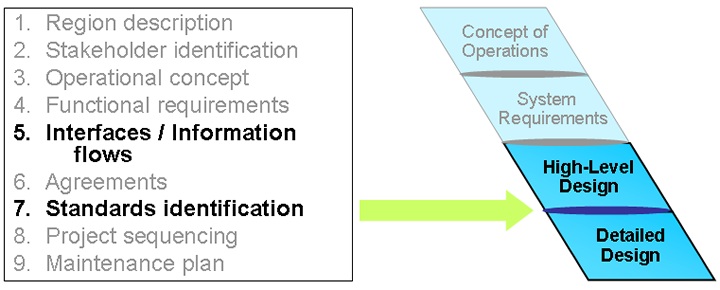
Figure 52: Architecture Use in Project Design
The subset of the regional ITS architecture identified in paragraph 7.3.3 forms the basis for the high-level or architectural design for the project. The subset of the regional ITS architecture should identify the key inter-agency interfaces (if any) that the project must support as well as major system interfaces. The project architectural design then adds significant detail, but retains traceability back to the architecture framework, as shown for the example Maine DMS project in Figure 53. By developing an architectural design for the project that maps back to the regional ITS architecture, there is traceability through the process, connecting planning and implementation.
Figure 53: Example DMS Project Architectural Design
The regional ITS architecture includes a map to ITS standards that can be used to identify the applicable ITS standards for the project. For example, the standards that are identified in the regional ITS architecture for the example Maine DMS project are shown in Table 16.
Table 16: DMS Project ITS Standards
| Document ID | Standard Title |
|---|---|
| NTCIP 1101 | Simple Transportation Management Framework (STMF) |
| NTCIP 1102 | Base Standard: Octet Encoding Rules (OER) |
| NTCIP 1103 | Simple Transportation Management Protocol (STMP) |
| NTCIP 1201 | Global Object Definitions |
| NTCIP 1203 | Object Definitions for Dynamic Message Signs |
| NTCIP 2101 | Point to Multi-Point Protocol Using RS-232 Subnetwork Profile |
| NTCIP 2102 | Subnet Profile for PMPP Over FSK modems |
| NTCIP 2103 | Subnet Profile for Point-to-Point Protocol using RS 232 |
| NTCIP 2104 | Subnet Profile for Ethernet |
| NTCIP 2201 | Transportation Transport Profile |
| NTCIP 2202 | Internet (TCP/IP and UDP/IP) Transport Profile |
| NTCIP 2301 | Application Profile for Simple Transportation Management Framework (STMF) |
| NTCIP 2302 | Application Profile for Trivial File Transfer Protocol |
| NTCIP 2303 | Application Profile for File Transfer Protocol (FTP) |
The standards that are identified in the architecture are only a starting point for the project design specification. Typically, only a subset of the identified standards will actually be used in the project and substantial detail must be included in the specification to identify the portions of the standard that are relevant to the particular procurement.
Some regions have created standards plans as part of their architecture that define the approach for incorporating standards into ITS projects over time. If such a plan exists, it should be consulted for guidance on standards implementation. Feedback should also be provided to the regional architecture maintenance organization if the standards plan does not accurately reflect the preferred use of standards on the project. Section 6.3.3 describes ITS standards plans in more detail.
Several resources describe how to specify
ITS standards requirements for ITS procurements. The ITS Standards Program web
site includes the most current information on ITS standards, including
available deployment resources (http://www.standards.its.dot.gov).
The specification of applicable ITS
standards is a required part of the Systems Engineering Analysis as specified
in the Rule/Policy.
Project Teams that use the architecture will be one of the most significant sources for regional ITS architecture maintenance changes. As projects are implemented, they will be mapped to the architecture, and a significant portion of the architecture will be closely reviewed in the process. Each region should define a mechanism that allows each Project Team to provide comments to the architecture with minimal time investment. Many of the components of the regional ITS architecture may be improved through feedback from architecture use, as shown in Figure 54. As discussed in paragraph 7.3.1, a checkpoint in the process should be identified where each project reviews the as-built project design and submits any comments to the regional ITS architecture, in the same way that as-built plans are submitted for traditional construction projects.
There are a few key steps that can be taken to implement a good architecture feedback process and ultimately improve the quality of the regional ITS architecture. First, there must be some rigor to the process that supports architecture feedback so that architecture feedback isn't forgotten in the rush to complete the project. Second, good configuration management practices are required, both for the project development team and the architecture maintainer so that needed changes are captured, accrued, and properly incorporated over time. Regional ITS Architecture maintenance is discussed in detail in Section 8.
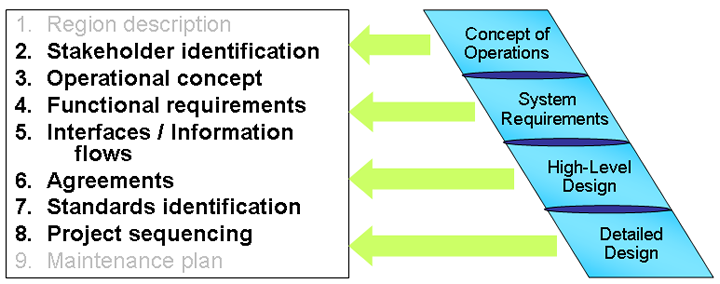
Figure 54: Providing Feedback to the Regional ITS Architecture
Several regions have implemented on-line forms and e-mail links that make it easier for Project Teams to provide architecture feedback. For example, VDOT provides an on-line form for architecture comments on their Northern Virginia (NOVA) ITS Architecture web site. Another form (see Figure 55) allows Project Sponsors to easily notify the NOVA Architecture Team leader of new Project Architectures that should be reflected in the NOVA Architecture. Architecture maintainers can also use programming documents, capital plans, project documentation, and general knowledge and involvement in the region to identify architecture impacts from ITS projects that may not be reported.
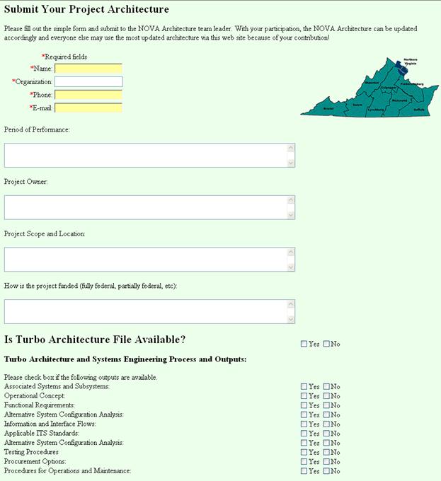
Figure 55: VDOT Project Architecture Submittal Form
TOC Previous Page Next Page