Recurring Traffic Bottlenecks: A Primer
Focus on Low-Cost Operational Improvements (Fourth Edition)
Chapter 6. Localized Bottleneck Reduction Strategies
Types of Localized Bottleneck Reduction Treatments
The following is a sampling of short-term, low-cost operational and geometric improvements. All of these remedies address operational deficiencies, as opposed to other congestion mitigation efforts that address driver choice, travel demand, corridor-wide upgrades, or simply (but expensively) building our way out of congestion.
For more information, please consult the FHWA publication "Use of Freeway Shoulders for Travel," February 2016, FHWA-HOP-15-023.
- Shoulder conversions. The Federal Highway Administration (FHWA) is currently studying the efficacy and prudence of using improved roadway shoulders to address congestion in particularly challenging situations. The safety implications of using shoulders, versus the congestion relief tradeoff of the same, is first-and-foremost at the discussion of this strategy. This involves using a short section of traffic-bearing shoulder as an additional travel lane, but only for peak hours. Shoulder conversions are most appropriate between interchanges or to provide lane congruency with adjacent sections. The improved shoulder should be rated for use as a travel lane. Practical challenges exist as to designing controls for part-time use versus 24/7 use.
- Restriping. Restriping improvements include: restriping existing pavement in merge or diverge areas to provide additional lanes or to improve lane balance, providing an acceleration/deceleration lane, extending the merge/diverge area, and improving geometrics to better serve demand.
- Minor interchange modifications. New auxiliary lanes can be added to connect closely spaced interchanges, extending the length of an exit lane to store queues from a ramp terminus and providing exit-only or "slip ramps" in advance of a major interchange are three examples. It is important to note that major interchange modifications (e.g., an entire interchange rebuild) would tend to be outside the purview of the "localized" solutions found in this primer.
- Lane width reductions. Such improvements involve reducing lane widths and restriping to add an additional travel and/or auxiliary lane.
- Modified weaving areas. Weaving areas can be modified by adding collector, distributor, or through lanes.
- Ramp modifications. Ramp modifications could include ramp metering; widening, extending, closing, or consolidating ramps; or reversing entrance and exit ramps to improve operations.
- Speed harmonization (variable speed limits). This is the practice of adjusting speed limits when congestion thresholds have been exceeded and congestion and queue forming is imminent. Speed harmonization can also be used to promote safer driving during inclement weather conditions. This mostly European practice reduces the traffic "shock wave" that results through congested corridors, thereby delaying the onset of a breakdown in traffic conditions. The result is decreased headways and more uniform driver behavior, which indirectly benefit bottlenecks and chokepoints.
- Zippering or self-metering that promotes fair and smooth merges. A motorist who is 10th in line knows that he will be 20th to merge into the single lane ahead. This helps to eliminate line jumpers that bull ahead, disrupt the queues, and often block adjacent lanes until they force their way in line. Usually this method of merging requires on-site enforcement, but often is exhibited by regulars who know the process and are conditioned to practice it.
- Improved traffic signal timing on arterials. Traffic signal timing improvements on arterials, as well as at ramp terminal intersections, will prevent ramp queues from backing up onto freeway main lanes.
- Access management principles to reduce vehicular conflicts (hence, delays) on arterial corridors. Access management addresses turn lanes, driveways, medians, permitting, site review, and lot access—to name but a few elements—and is its own field of study.
- Roundabouts. Roundabouts may be used in place of stop sign or signal controlled intersections, including replacing signalized intersections at ramp termini.
- Innovative intersection and intersection designs. A variety of new designs are being implemented around the country (see below).
- High occupancy vehicle (HOV) or reversible lanes.
- Traveler information on traffic diversions.
- Congestion pricing. Congestion pricing entails charging fees or tolls for road use that varies by level of vehicle demand on the facility. The objective is to bring supply and demand into alignment.
Advanced Forms of Bottleneck Treatments Already In Practice
Dynamic Lane Grouping
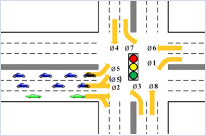
Conventional traffic signal control assumes the intersection's lane assignment configuration is fixed. Dynamic lane grouping (DLG) aims to adjust lane assignment based on fluctuating travel demand to further improve intersection capacity utilization. In the example shown in Figure 11, the through lane on the left-to-right movement has been converted into a shared through and left turn lane. This dynamic lane grouping is implemented when left turn volumes are high enough to cause significant delay on the approach. This treatment also requires that changes to the signal heads be made as well as to the phasing plan. Before this treatment is used, analysis of the through movement demand must be made to ensure that delay is not being transferred to it.
Figure 11. Schematic. Example of dynamic lane grouping at a signalized intersection.
(Source: Federal Highway Administration.)
Dynamic Junction Control
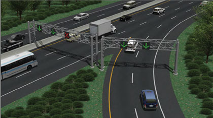
In response to growing traffic congestion, an increasing number of active traffic management (ATM) strategies have been developed and implemented internationally. Dynamic junction control (DJC), sometimes called dynamic merge control, is a relatively new type of treatment. It is implemented at freeway on-ramp locations where the entering volume is high in relation to the mainline volume. If the on-ramp is configured as a single lane merging onto the freeway, high ramp volumes can cause significant delay on the ramps. Additionally, lane drops in the merge area can easily cause a bottleneck, leading to upstream congestion on both roads. If the mainline volume is low enough, DJC assigns one of the mainline lanes as a merge lane. DJC can also be applied at freeway-to-freeway merge areas as well. Figure 12 shows an on-ramp situation where an on-ramp has been dynamically assigned as two lanes during times of heavy on-ramp flow.
Figure 12 . Simulation graphic. Dynamic junction control implementation.
(Source: Federal Highway Administration.)
Acceleration Lane Extension
On freeways, merging at the terminus of an acceleration lane often causes a severe traffic bottleneck. In traffic simulation studies, it was found that lengthening acceleration lane lengths reduced delay by 9 to 14 percent.
Part-Time Shoulder Use
There are many forms of part-time shoulder use or "shoulder running"; they all involve use of the left or right shoulders of an existing roadway for temporary travel during certain hours of the day. Part-time shoulder use is employed on freeways and there are multiple examples of how highway agencies have used the shoulders of roadways to address congestion and reliability needs and to improve overall system performance. These options vary in terms of the location of the shoulder (left/right shoulder options) used, vehicle-use options (e.g., bus only, high-occupancy vehicle (HOV) only, all vehicles except trucks), operating schedule, and special speed controls. In all of these options, the use is "temporary" for part of the day, and the lane continues to operate as a refuge/shoulder when not being used for these travel purposes. This condition is referred to as "part-time shoulder use" throughout this guide. Simulation studies showed that part-time shoulder use reduced delay by 9 to 20 percent.
Reducing Lane and Shoulder Widths to Add a New Lane
In congested freeways with four lanes or more, reducing lane widths to 10 feet can create space for an additional lane. This can often be done without any construction or requisition of additional space. According to simulation results, the additional capacity obtained by adding a lane was effective at offsetting the reduced speeds caused by narrow lanes, eliminating bottlenecks, and producing higher corridor speeds. Specifically, reducing lane widths from 12 to 10 feet on the four-lane corridor and adding an additional 10-feet lane reduced overall corridor delay by 21 percent. Real-world implementations of 10-feet freeway lanes have occurred in California and Hawaii, as discussed later in the benefit-cost analysis section. Other reduced-width (11-feet) lanes were created on the I‑75 and I‑85 corridors in Georgia inside the I‑285 perimeter. They were installed in combination with requirements that through trucks must bypass downtown Atlanta, GA, by using I‑285.
Innovative Intersection and Interchange Design Treatments
In recent years, several nontraditional designs have been developed for signalized intersections and interchanges. The alternative designs for intersections all attempt to remove one or more of the conventional left-turn movements from the major intersection. By removing one or more of the critical conflicting traffic maneuvers from the major intersection, fewer signal phases are required for signal operation. This can result in shorter signal cycle lengths, shorter delays, and higher capacities compared to conventional intersections. Figures 13 through 18 show examples of these innovative designs.
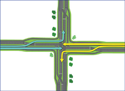
One innovative intersection design is the continuous flow intersection, which eliminates one or more left-turn conflicts at a main intersection. This is achieved through dedicated left-turn bays located several hundred feet prior to the main intersection, which allow left-turning vehicles to move at the same time as through traffic. The left-turn traffic signal phase is eliminated, allowing more vehicles to move through the main intersection and thus reducing traffic congestion and delays. These at-grade intersections achieve traffic flow similar to grade-separated interchanges, but at a considerably lower cost. Other innovative intersection designs include:
- Displaced left-turn (DLT) intersection.
- Median U-turn (MUT) intersection.
- Restricted crossing U-turn (RCUT) intersection.
- Quadrant roadway (QR) intersection.
Figure 13. Schematic. Vehicular movements at a continuous flow intersection.
(Source: Federal Highway Administration.)
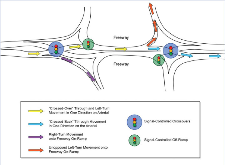
The double crossover diamond (DCD) interchange, also known as a diverging diamond interchange (DDI), is a new interchange design that has much in common with the design of a conventional diamond interchange, The main difference between a DCD interchange and a conventional diamond interchange is in the way left and through movements navigate between the cross street intersections with ramp. The DCD design accommodates left-turning movements onto arterials and limited access highways while eliminating the need for a left-turn signal phase at signalized ramp terminal intersections. On the cross street, the traffic moves to the left side of the roadway between the signalized ramp intersections. This allows drivers of vehicles on the cross street who want to turn left onto the ramps the chance to continue to the ramps without conflicting with opposing through traffic and without stopping.
Figure 14. Schematic. Crossover movement in a double crossover diamond (DCD) interchange.
(Source: Federal Highway Administration.)
Median U-Turn Intersection
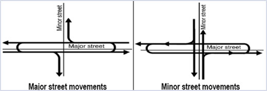
The median U-turn (MUT) intersection seeks to balance safety and congestion problems at intersections. The MUT intersection involves the elimination of direct left turns from major and/or minor approaches (usually both). Drivers desiring to turn left from the major road onto an intersecting cross street must first travel through the at-grade main intersection and then execute a U-turn at the median opening downstream of the intersection. These drivers then turn right at the cross street. Drivers on the minor street desiring to turn left onto the major road must first turn right at the main intersection, execute a U-turn at the downstream median opening, and proceed back through the main intersection. Elimination of left-turning traffic from the main intersection implies the signal operations at the intersection, which accounts for most of the benefits
Figure 15. Schematic. Median U-turn (MUT) intersection.
(Source: Federal Highway Administration.)
Restricted Crossing U-Turn Intersection
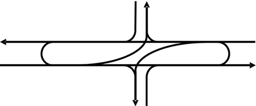
Restricted crossing U-turn (RCUT) intersections, also referred to as super street intersections, are a promising solution for arterials with more dominant flows on the major road. They have the potential to move more vehicles efficiently and safely than roadways with comparable traffic volumes that have conventional at-grade intersections with minimal disruptions to adjacent development. The RCUT intersection works by redirecting left-turn and through movements from the side street approaches. Instead of allowing those movements to be made directly through the intersection, as in a conventional design, a RCUT intersection accommodates those movements by requiring drivers to turn right onto the main road and then make a U-turn maneuver at a one-way median opening 400 to 1,000 feet downstream.
Figure 16. Schematic. Restricted crossing U-turn (RCUT) intersection.
(Source: North Carolina Department of Transportation.)
Figure 17. Photo. U.S. Route 17 restricted crossing U-turn intersection corridor in Leland, North Carolina.
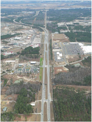
(Source: Federal Highway Administration, Restricted Crossing U-turn Informational Guide.)
Quadrant Roadway Intersection
A quadrant roadway (QR) intersection is a promising design for an intersection of two busy suburban or urban roadways. The primary objective of a QR intersection is to reduce delay at a severely congested intersection and to reduce overall travel time by removing left-turn movements. A QR intersection can provide other benefits as well, such as making it shorter and quicker for most pedestrians at the intersection. A QR intersection can be among the least costly of the alternative intersections to construct and maintain.
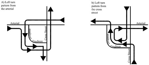
At a QR intersection, all four left-turn movements at a conventional four-legged intersection are rerouted to use a connector roadway in one quadrant. Figure 18 shows the connector road and how all four of the left-turning movements are rerouted to use it. Left turns from all approaches are prohibited at the main intersection, which consequently allows a simple two-phase signal operation at the main intersection. Each terminus of the connector road is typically signalized. These two secondary signal-controlled intersections usually require three phases.
Figure 18. Schematic. The quadrant roadway (QR) intersection.
(Source: Federal Highway Administration.)