Roles of Transportation Management Centers in Incident Management on Managed LanesChapter 1-Introduction and BackgroundManaged lanes are becoming an increasingly popular strategy for addressing the problem of traffic congestion in major metropolitan areas, as these are lanes designed to optimize the movement of large numbers of people within a small amount of roadway space. In order to accomplish this goal, managed lanes must respond to both recurring changes in traffic patterns and non-recurring incidents. The purpose of this guidebook is to document traffic incident management (TIM) practices that can be implemented from a transportation management center (TMC) within the managed lane operating environment. It provides a framework for successful development and implementation of a TIM program for planners designing new managed lane facilities, as well as for transportation professionals with existing facilities looking to optimize the use of their TMC as part of their TIM program.
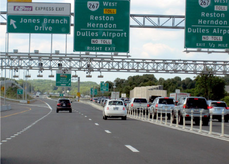
Figure 1. Photo. Uncongested managed lanes adjacent to congested general purpose lanes. For the purpose of discussion in this guidebook, the term TMC is used in a broad sense. Its connotation is not limited to "direct" operational activities such as traffic monitoring and management or incident detection and response. Neither is it limited to consideration of personnel involved in these "direct" operational activities such as TMC operators or shift supervisors. Rather, the term TMC in this guidebook is a broader term which relates to the fact that TMCs are often an element of a larger program that performs or supports other activities, including strategic and operational planning, system design, and coordination of operational stakeholders. The content of this guidebook is divided into six chapters as follows:
1.1 Definition of Managed LanesThere are several different definitions of managed lanes used by different sectors of the transportation community. While managed lanes can cover a broad range of facilities, the definition of managed lanes used in this guidebook is narrower.
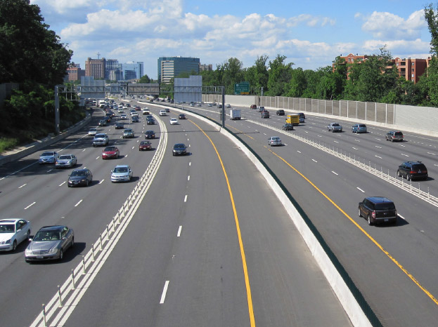
Figure 2. Photo. Managed lanes function as a "freeway within a freeway". The Federal Highway Administration's (FHWA's) definition of managed lanes is: "Highway facilities or a set of lanes where operational strategies are proactively implemented and managed in response to changing conditions." This definition is very broad and encompasses a wide variety of facility types, ranging from dynamically priced express toll lanes to simple curbside urban transit lanes. This guidebook focuses on freeway managed lanes with actively managed operations, eligibility restrictions, and access restrictions that co-exist adjacent to non-managed general purpose lanes. From an operational perspective, these lanes operate as a "freeway within a freeway" with the managed lanes functioning separately from the general purpose lanes. Some facilities are considered managed lanes based on the FHWA definition, but are not a freeway within a freeway. Such facilities include stand-alone dynamically priced toll roads where all lanes are tolled, exclusive busways, and managed lanes on non-freeways. These facilities are not covered in this guidebook as TIM practices for these roadways are very similar to TIM on a normal freeway or urban arterial roadway. 1.2 Access to Managed LanesThe success of a managed lane facility depends upon the ability to maximize the use of available capacity while regulating vehicular demand to prevent the lane from becoming saturated. There are various methods that can be implemented to regulate demand by controlling access to managed lanes. These methods can be used to manage traffic during an incident. Descriptions of the most common access control methods as they operate under normal circumstances are discussed below. High Occupancy Vehicle (HOV) LanesA managed lane facility with a vehicle eligibility restriction that reserves the managed lane(s) for the exclusive use of vehicles with a driver and one or more passengers, including carpools, vanpools, and transit vehicles. HOV lanes may operate at all times, or only during peak hours with the lane open to general traffic during other time periods. Some vehicles are exempt from HOV access restrictions depending on the jurisdiction's laws, such as electric vehicles, hybrid vehicles, transit buses and taxis with no passengers, and emergency vehicles.
Figure 3. Illustration. MUTCD sign showing HOV lanes have a minimum vehicle occupancy requirement. Express Toll Lanes (ETLs)Managed lanes that charge a toll for access to the lane. Many ETLs utilize congestion pricing, where tolls increase as traffic volumes, traffic densities, or congestion increase. The theory is that a higher price will reduce demand and thus reduce congestion by "pricing out" vehicles whose drivers do not wish to pay the higher fee for access. ETLs may have rates that adjust on a set schedule, or the rates may adjust dynamically depending on the traffic conditions in the lanes. ETLs use electronic toll collection in order to collect tolls with minimal disruption to traffic flow, and thus many require enrollment in an electronic toll collection program in order to use the lanes.
Figure 4. Illustration. MUTCD sign showing ETLs with congestion pricing have variable tolls. High Occupancy/Toll (HOT) LanesHOT lanes are a hybrid between HOV lanes and ETLs. An occupancy requirement is set, and vehicles meeting the occupancy requirement can travel in the managed lane for free, while vehicles not meeting the occupancy requirement must pay a toll to travel in the lane. The toll structure typically utilizes congestion pricing to manage congestion in the lanes. Some HOT lanes require all vehicles to enroll in an electronic toll collection program and to carry a transponder, while other HOT lanes allow free use by HOVs with no transponder or toll account.
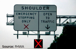
Figure 5. Illustration. MUTCD sign showing HOT lanes are ETLs where HOVs do not pay for access. Bus LanesBus lanes have a vehicle eligibility restriction permitting use only by buses. The restriction may allow any bus to use the facility, or it may restrict use to transit buses only. Bus lanes prioritize mass transit vehicle movement and are less prone to congestion than other types of lanes which allow cars to enter. In some cases, authorized transit buses are permitted to utilize the roadway shoulder to bypass traffic congestion. This is a type of bus lane that has fewer capital costs to implement, but requires additional training for bus drivers to use the shoulder while maintaining a safe operating environment for the buses, general traffic, and disabled vehicles parked on the shoulder. The access control methods discussed above represent most common strategies for controlling access to a managed lane. The details of how the strategies are implemented can vary widely among different facilities. The type of access control and the level of flexibility in adjusting the access requirements can potentially play a big role in TIM in the managed lanes. 1.3 Physical Design of Managed LanesManaged lanes are located next to general purpose lanes and there are varying degrees of physical separation between the two. The level of separation plays an important role in how authorities respond to incidents. The following is a brief overview of typical physical designs of managed lane facilities. ShoulderThe right or left shoulder of the roadway is used as a full-time or part-time managed lane, and use of the shoulder is typically regulated by electronic signs. When the managed lane is in operation, there is reduced or no shoulder space on the side of the roadway with the managed lane. When the managed lane is not in operation, the shoulder can be used for emergency stopping or incident clearance. In some cases, shoulder use is restricted to authorized transit buses. There are fewer electronic signs, as there is a driver training component for all drivers utilizing the lanes.
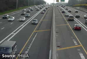
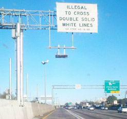
Figure 6. Photo. Part-time shoulder lane. Painted BufferThe managed lane is separated from the general purpose lanes with a double white line or a wider painted "buffer area" that is illegal to cross. The painted buffer can be as narrow as 4 feet or wide enough for a disabled vehicle to fit between the lanes. Entering and exiting the managed lane is accomplished using gaps in the painted buffer where vehicles are allowed to change lanes. Alternatively, painted "slip lanes" that function as an acceleration/deceleration lane between the managed and general purpose lanes can be used. Painted buffers allow easy access to the managed lane during incidents, but rely heavily on voluntary compliance with buffer crossing prohibitions during normal operations.
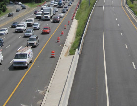
Figure 7. Photo. Managed lane separated from general purpose lanes with painted buffer. Continuous Access LaneThe managed lane operates as a typical freeway lane with some form of usage restriction. Drivers may enter and exit the lane at any location. This physical design allows easy access for incident response. For part-time managed lane facilities, the lane can either be closed or operated as an additional general purpose lane outside the typical operating hours.
Figure 8. Photo. The left lane is a continuous access HOV lane. Painted Buffer with Electronic "Invisible" BarrierThis design is the same as the painted buffer, with the addition of an electronic system to deter drivers from illegally crossing the buffer. This system uses a series of cameras, license plate readers, and/or toll transponder readers to detect when a car enters or exits the managed lane between legal entry/exit points. A warning or violation notice is sent to drivers who do not follow the posted rules. This system provides a deterrent to illegal crossing of the buffer, and it can be easily deactivated if crossing the buffer is needed for incident response.
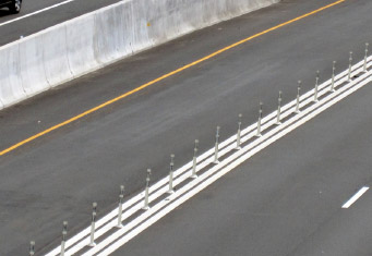
Figure 9. Photo. Invisible electronic barrier using toll tag readers and cameras. Plastic Post BarrierThis design utilizes flexible plastic posts, sometimes referred to as "candlesticks", placed inside a painted buffer area to separate the managed lanes and general purpose lanes. The posts can be located adjacent to the travel lanes, or there can be a paved shoulder between the posts and the travel lane. Plastic posts will not stop an errant vehicle from crashing through the barrier, but most drivers will typically avoid deliberately crossing the barrier. The posts can be removed if necessary to provide responder access to the managed lanes. The use of plastic posts may be impractical in northern climates due to the increased maintenance costs associated with damage caused by snow removal activities. However some agencies with priced managed lanes and lower rates of driver compliance with signs and markings may justify the increased maintenance costs if the plastic posts are used for revenue protection purposes.
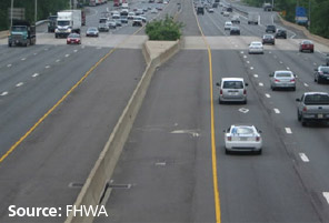
Figure 10. Photo. Plastic post barrier. Permanent Physical BarrierA permanent physical barrier, such as a Jersey barrier, physically separates the managed and general purpose lanes. There is typically a full shoulder between the travel lane and the barrier. The managed lanes operate as a completely separate roadway from the general purpose lanes. This design prevents errant vehicles from crossing the barrier, but also restricts emergency access to defined access points along the facility.
Figure 11. Photo. Permanent physical barrier creates two separate roadways. Zipper BarrierA zipper barrier is a physical barrier that can be moved by a special mobile machine. Zipper barriers are often used to create "contraflow lanes", where a lane in the off-peak direction of travel is used for travel in the peak direction. The zipper barrier has the advantage of physical separation between lanes, as it will stop most errant vehicles. The zipper barrier also has the advantage of flexibility in operations, since it can be moved to open or close lanes as needed. Typically the barrier is moved according to a set schedule usually around commuter peak periods; however it is also possible to move the barrier in the case of an incident.
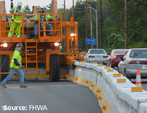
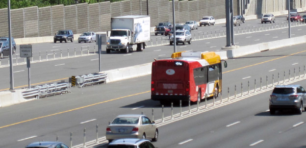
Figure 12. Photo. Zipper barrier and mobile machine. Reversible RoadwayThese managed lanes are entire roadways that reverse direction, and are typically built to handle large directional peaks in traffic volumes. Reversible roadways are usually located between the two sets of general purpose lanes, but can also be elevated or located off to one side. The entry and exit points to a reversible roadway are carefully controlled with dynamic message signs (DMSs), signals, and gates to prevent wrong way entry into the lanes during normal operations. During incidents these features can be used to control access to the lanes or allow emergency access. 1.4 Importance of TIM in Managed LanesTIM is the process of coordinating the resources of a number of different partner agencies and private sector companies to detect, respond to, and clear traffic incidents as quickly as possible in order to reduce the impacts of incidents on safety and congestion, while protecting the safety of on-scene responders and the traveling public. Efficient TIM is important because when an incident occurs, congestion quickly builds up and the likelihood of a secondary incident increases.
Figure 13. Photo. An incident in a managed lane can inconvenience many people, such as transit riders, since vehicle occupancies are high. The sooner an incident is detected, the sooner safety personnel can respond to it and clear it from the roads allowing traffic lanes to re-open and traffic to return to normal conditions. TIM assists with the process of creating a safe work area with proper signs and equipment for emergency crews responding to an incident. The effects of an incident and the importance of TIM are compounded in the managed lane environment for the following reasons:
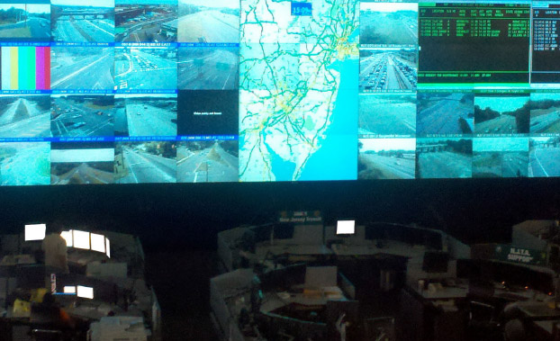
A robust and effective TIM program will ensure that managed lane facilities operate as reliably as possible and that downtime is minimized. This in turn will provide an acceptable level of service to the greatest number of people and the vehicles with the highest priority within the transportation network, such as HOVs or transit vehicles. 1.5 TMC OperationsThe TMC is the most important TIM resource. The TMC is a centralized hub that provides real-time monitoring of the highway, incident detection and verification, coordination and support for incidents, and distribution of traveler information. The TMC helps to reduce congestion, increase safety, and increase the efficiency of the transportation network. These goals are typically achieved using the TMC's communications capabilities and its access to ITS assets on the roadway network. Typical TMC TIM functions and capabilities include:
Figure 14. Photo. Inside of the New Jersey Statewide Transportation Management Center. |
|
United States Department of Transportation - Federal Highway Administration |
||