Travel Time on Arterials and Rural Highways: State-of-the-Practice Synthesis on Rural Data Collection Technology2. Data Source SummariesA variety of technologies and data sources can be used as the basis for travel time calculations. These include:
Some of these technologies are mature and widely used, while others have emerged recently or are still in the early stages of development. While the set of technology options is largely the same for urban freeways, arterials, and rural roads, not all technologies are equally suited to all road types, environments, and topographies. This review of technologies is focused on the implementation considerations for rural highways. In addition to documenting information about the technologies themselves, the review effort addresses the integration of these technologies with existing systems and infrastructure. This chapter summarizes technologies that can be used to capture RTT data. The summaries emphasize the tangible aspects of the data sources (e.g., hardware and installation requirements, implementation considerations, costs), but also address capabilities and disadvantages of each technology, potential privacy concerns, and other less tangible issues. Table 3 briefly summarizes candidate technologies, and then each technology is discussed further in its own subsection. Data transmission and processing are important aspects of RTT implementations, but are not addressed in detail in this section because they are largely independent of data source. Similarly, although data sources are described individually in this section, an important trend in travel time monitoring is data integration, or "data fusion," which allows agencies to harness data from multiple sources to improve the quality, reliability, and comprehensiveness of information. Data transmission, processing, and use are discussed further in Chapter 4.
2.1 Bluetooth DetectionAt a Glance
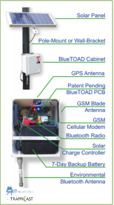
How it Works Bluetooth is a non-proprietary wireless technology standard that allows electronic devices to communicate directly with one another over relatively short distances using radio frequency communication. Since its development in the 1990s, Bluetooth has become a ubiquitous feature on a variety of electronic devices, including mobile phones, computers, hands-free headsets, and even vehicles themselves. Bluetooth detection systems work by actively searching for in-range Bluetooth devices and capturing the unique media access control (MAC) address of each device. For a Bluetooth detection system to read the MAC address of a device, the device must be turned on and be in "discoverable" mode (i.e., broadcasting its MAC address). Because each device has a unique and permanent MAC address, Bluetooth detection systems can determine vehicle travel times and speeds by calculating the time it takes for vehicles containing Bluetooth devices to travel between two or more Bluetooth sensors that are a known distance apart. State of the Technology Although the Bluetooth standard is nearly 20 years old, Bluetooth detection for travel time data collection has only emerged as a viable option in recent years, largely due to the rapid growth in the adoption of Bluetooth-enabled devices. Despite its relatively recent emergence, Bluetooth detection is among the most commonly used technologies for calculating ATT. Hardware and Installation Bluetooth detection offers a wide range of hardware and installation options. Because Bluetooth is an open standard, it is possible to assemble detector systems using off-the-shelf components, though complete systems can also be purchased or leased from vendors. An example of a solar-powered, pole-mounted detector is shown in Figure 2. Detector units can be placed in any location near the roadway as long as there are no major line-of-sight obstructions. Reliable detection distance can reach up to 328 feet (100 meters), allowing for flexibility in placement that may be particularly beneficial on rural roads with challenging topographies. An evaluation by Click and Lloyd (2012) found that Bluetooth detectors placed in the center of a wide rural median do not detect vehicles as effectively as when they are placed on the roadside, so for wide rural roads, two roadside detectors may be more effective than one median detector. Units can be pole-mounted, fastened to existing infrastructure, installed in a signal cabinet, or, if powered by battery, briefcase-size units can be placed in any desired location (preferably chained to a fixed object for security). However, detection rates are likely to be higher when sensors are elevated rather than placed on the ground (Puckett & Vickich, 2010). Fixed units can be powered by existing power infrastructure or solar panels, and battery-powered units can typically operate between two to three weeks on a single charge. The relatively low power consumption of Bluetooth detectors is a particular benefit when infrastructure power is unavailable. Units can work with existing communications infrastructure or record to local hard drives. When given protection from precipitation and extreme temperatures, device maintenance requirements and failure rates can be very low.
Implementation Considerations Bluetooth detection sensors detect any "discoverable" Bluetooth-enabled devices within a radius of about 328 feet (100 meters), if using a high-powered antenna. Detection range can be reduced by using a lower gain antenna. Measuring the travel time of an individual vehicle along a road segment is as simple as comparing the time when the vehicle is detected at the beginning of the segment to the time when the vehicle is detected at the end of the segment. Dividing the length of the segment by the vehicle's travel time yields an average speed for the segment. Additional data can be acquired by observing the duration that a vehicle is within the detection zone of a single Bluetooth sensor (e.g., a sensor near a major intersection could potentially provide data on signal queue) (Tsubota, Bhaskar, Chung, & Billot, 2011). Some Bluetooth detection devices include global positioning systems (GPS), which allow each device to be precisely located and provides automatic time synchronization between devices, ensuring accurate travel time calculations. As with other travel time data collection technologies, accurate travel time estimates depend not only on accurate data collection, but also on sufficient detection rates over time as well as the use of algorithms capable of discarding outlier data. These issues are addressed in detail in Section 4.2. Another potential limitation of some versions of Bluetooth detection is the system's "inquiry time." The system initially deployed in Houston, TX, only reported detected vehicles within a 10-second inquiry window, and therefore all vehicles detected within this window will report the same detection time. This inaccuracy could lead to travel time inaccuracies, especially over short segment lengths. Furthermore, only a maximum of eight detections could be reported within each inquiry window. This has implications for the potential to match vehicles at multiple detector locations during heavy traffic periods (Puckett & Vickich, 2010), though this might not be an issue on many lower-volume rural roads. Newer generations of Bluetooth detection systems, however, are capable of asynchronous input/output, which allows data to be output as soon as it is read. While proper placement should ensure the detection of discoverable devices on the intended roadways, it is possible that the non-directional sensors will also detect devices on nearby roadways, parking lots, and other surrounding areas. While data processing algorithms can identify and remove many of the "noise" detections from the dataset, it is best to place Bluetooth detectors where unintended detections will be minimized. Unintended detections can also be reduced by using a lower powered antenna, but care must be taken to ensure that intended detections are not reduced as well. Costs Bluetooth detection systems are significantly less expensive than most alternative travel time detection technologies. Bluetooth detectors themselves are inexpensive and the complementary hardware (e.g., modem) is also inexpensive. Prices per location vary depending upon the type of installation. For instance, installation in an existing traffic signal cabinet is likely to be substantially cheaper than a solar-powered stand-alone implementation. Depending upon the hardware and installation requirements, Bluetooth detection systems may cost as little as $1,000 and $8,000 per location when purchased from a vendor. Given the relative newness of Bluetooth technology for traffic detection, limited information exists on life span and maintenance costs, though experience in Chandler, AZ suggests that the devices can function for a period of years without maintenance or adjustment. Privacy Issues Bluetooth detection systems work by reading the MAC addresses of in-range Bluetooth-enabled devices, which are unique and permanent identifiers linked to a single device. MAC addresses are not linked to device sales records, so there is no direct way to match a MAC address with an individual owner or user. This affords device users a layer of privacy. However, there are indirect methods that could hypothetically be used to match MAC addresses to individuals. For instance, if an electronic device were seized by police as evidence, the MAC address could be determined and matched against Bluetooth detection records. Similarly, users who download and use certain mobile device applications may make personal information, including their MAC addresses, known to the apps' publishers, who could then potentially mine, share, or sell this information. While these cases are hypothetical, implementers should consider the issues they raise, and the additional steps that can be taken to further safeguard the public's privacy. These measures include truncating the MAC address so that only a portion of the address is used to make the match (e.g., using only four of the address' twelve digits), randomly reassigning a different unique identifier, and/or deleting or randomizing MAC addresses after their immediate use is complete. Strong data encryption should also be used an added layer of security against unauthorized access. Future Considerations The future viability of Bluetooth detection systems is dependent upon the continued prevalence of Bluetooth-enabled devices. Although there are currently no technologies on the horizon that appear to be in a position to replace Bluetooth, the generational life span of mobile technologies is often short, and if a new technology does emerge to replace or obviate Bluetooth detection, the market penetration of Bluetooth may decline very quickly. If this does occur, existing Bluetooth detection systems will either need to be replaced or retrofitted for compatibility with the new technology. For example, WiFi could eventually become a dominant in-vehicle technology and Bluetooth detectors could be replaced or retrofitted to detect WiFi devices rather than, or in addition to, Bluetooth devices. Nonetheless, Bluetooth appears poised to remain dominant for the foreseeable future. Furthermore, an increasing number of vehicle models are manufactured with built-in Bluetooth devices. The average life span of a vehicle is significantly longer than the average life span of a portable electronic device, so it is possible that the existence of a fleet of Bluetooth-enabled vehicles will extend the viability of Bluetooth detection even longer into the future. 2.2 Toll Tag ReaderAt a Glance
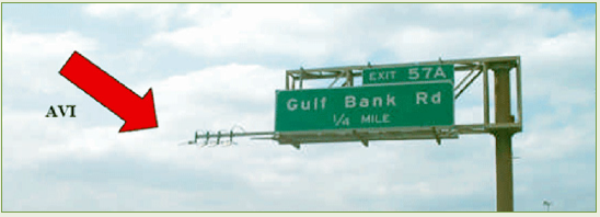
How it Works Toll tag readers, also known as automatic vehicle identification (AVI) systems, detect the unique radio frequency IDs of motorists' automated toll tags (e.g., E-ZPass) at multiple locations and calculate travel times based on the arrival time at each location. A vehicle must have a toll tag to be counted, so the technology is only feasible where a sufficient percentage of vehicles have toll tags. Alternative radio frequency identification (RFID) devices could also be used as an identifier, but no viable plan exists to use such a system. State of the Technology Toll tag readers are a mature technology. They have been used at toll facilities for more than 25 years and have been used to provide real-time travel time data by Florida Department of Transportation (DOT) and Houston TranStar. Hardware and Installation Toll tag readers can be inconspicuously placed directly above the roadway or on the roadside. Figure 3 shows an example of a toll tag reader fastened to a cantilever. Readers are most accurate when located close to passing vehicles and when aimed directly at a single travel lane (i.e., overhead on multi-lane facilities). Detection accuracy can decrease when placed farther from the road, when aimed at multiple travel lanes, and when there are physical obstructions between the sensor and the vehicle (Haas et al., 2009). Figure 3. Toll Tag Reader (AVI) in Houston,
TX Implementation Considerations Toll tag readers are only feasible for collecting travel time data on routes where a sufficient percentage of vehicles have toll tags. As noted above, toll tag readers must be appropriately positioned to achieve high detection rates. To achieve the highest detection rates, multiple readers may be required to cover all lanes of a multi-lane road. However, a single reader may be sufficient at each location if traffic volumes of detectable vehicles and match rates are high enough to generate accurate travel times. Another implementation consideration for toll tag readers is the potential for reader failure. A major toll tag reader deployment undertaken in the iFlorida Model Deployment experienced a device failure rate of about 50 percent during the course of the evaluation. At any given time, about 10 to 20 percent of toll tag readers were not functioning properly (Haas et al., 2009). Although device failure is highly dependent upon many implementation factors (e.g., operating temperature, power conditioning), the potential for failure should be considered. Best practices for minimizing and responding to device failure are presented in Section 4.3. Costs Costs of toll tag reader implementations can vary significantly depending upon implementation factors such as number of readers per location, distance between reader sites, and mounting location. According to Cambridge Systematics (2012), the cost per installed reader is about $15,000. According to Hardigree (2011), a multi-lane implementation of toll tag readers can cost $75,000 or more per location. Voigt (2011) estimates that toll tag readers can cost $75,000 to $125,000 per arterial site, excluding the cost of communications. According to Wright and Dahlgren (2000), "Capital costs per reader site where such systems have been implemented range from $18,000-$38,000 [for a six-lane roadway] and for the operations center from $37,000 to $86,000. Annual operating costs range from $4,000 to $6,000 per detector site and $48,000 to $96,000 for the operations center." Privacy Issues Toll tag readers read the unique IDs of each toll tag. Although toll tag IDs do not directly identify individuals, the ID can easily be used to identify the tag owner by matching the ID against the tolling authority's database of owners. As with Bluetooth detection, motorist privacy can be enhanced by truncating or transforming the toll tag IDs before the data are transmitted to the transportation agency. Future Considerations Toll tag reading is a mature technology that is likely to remain viable for the foreseeable future. Electronic tolling is increasingly common. Although the emerging connected vehicle technology (see Section 2.6) uses a very similar detection technology, its privacy restrictions may make connected vehicle technology an unsuitable replacement for segment travel time data collection. 2.3 In-Pavement Magnetic DetectorsAt a Glance
How it Works Arrays of magnetometers are installed in pavement at detection locations. The magnetometers can identify and match vehicles at multiple locations based on each vehicle's unique magnetic signature as it interacts with Earth's magnetic field. Additional information on magnetometers can be found in the Federal Highway Administration (FHWA) Traffic Detector Handbook (Klein, Mills, & Gibson, 2006).
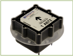
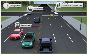
State of the Technology In-pavement magnetic detection has existed for decades, and has been used to collect travel time data via vehicle re-identification for about 10 years. It has been used in various locations for vehicle counts and classifications, traffic signal actuation, and travel time calculation. Agencies using magnetic detectors to provide real-time ATT data include Missouri DOT and Utah DOT. The only commercially available magnetic detector capable of real-time data transmission identified in this review is marketed by Sensys Networks, so this technology review focuses on the capabilities of the Sensys sensor. Hardware and Installation Each magnetic detector is slightly larger than a hockey puck (see Figure 4). Detectors are installed in pavement by drilling a core, inserting the detector in the proper orientation, and filling the hole with epoxy. Each detector can be installed in 15 minutes and requires no calibration. To be capable of matching vehicles at multiple locations to generate travel time data, an array of five sensors is needed in each monitored lane (Gregory Owens, personal communication, October 2012). Unlike traditional loop detectors, magnetic detectors can function wirelessly and can have a battery life of up to 10 years. Relative to wired inductive loops, magnetic detectors are easier to install, have limited effect on traffic disruption, and are less prone to failure. Additional repeaters may be used to extend wireless connection range. Figure 5 shows a typical installation configuration. Implementation Considerations An advantage of magnetic detectors over some other probe vehicle technologies is that the detection rate for vehicles passing over the monitored lane approaches 100 percent (though missed detections and double-detections are possible), providing transportation agencies with volume data that can be used for various purposes. A comparison to ground truth video data ("ideal" output of perfect detection/ tracking applied to the video stream) conducted by Sensys showed that in-pavement magnetometers achieved a 70 percent vehicle match rate (Volling, n.d.). The high detection and match rates may be particularly advantageous on low volume roads. If traffic volumes are sufficient, cost savings can be achieved by only installing sensors in one travel lane. Sensys generally recommends installing sensors in only the left through lane of a road because this lane carries the most through traffic and is least affected by vehicles entering and exiting the roadway. Due to the invasive nature of the installation, in-pavement magnetometers are not likely to be practical for short-term deployments. Additional data such as vehicle class can also be derived from this technology, though additional sensors may be required in an array. However, research by Medina, Hajbabaie, and Benekohal (2010) cautions that magnetic detectors may over count vehicles at or near signalized intersections by 16 to 22 percent, largely due to detections of vehicles in adjacent lanes or vehicles positioned between lanes. Day, Premachandra, Brennan, Sturdevant, and Bullock (2009) also found that magnetic detectors may miss detections of motorcycles if the motorcycle does not pass directly over the detector. Although installed in pavement, Sensys sensors can perform diagnostic checks and software upgrades remotely. Devices can be removed from pavement and reused.
Costs Costs for in-pavement magnetic detectors depend upon a number of factors, including number of sensors per array and the number of arrays per location (i.e., number of lanes monitored). Costs may also vary depending upon other services provided by the technology vendor. Although in-pavement magnetic detection is likely to cost significantly more than Bluetooth detection, the devices are expected to require little to no maintenance during their reported 10 year battery life. However, road work may require the devices to be removed before the end of their battery life. Privacy Issues Because magnetic detectors rely on a vehicle's magnetic signature, which can change depending upon vehicle occupancy and other factors, they offer a very high degree of inherent motorist privacy. An anonymous identifier is assigned to a vehicle that allows it to be re-identified at a downstream location. Future Considerations There are no emerging trends that are expected to influence the use of in-pavement magnetic detection. It is a viable solution for RTT data collection, as long as communications are available, and is expected to remain so. 2.4 Automatic License Plate Readers (ALPR)At a Glance
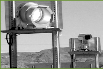
How it Works Optical cameras capture images of license plates of oncoming or receding traffic and use video image processing to "read" the license plates. License plate numbers can then be matched at sensor locations downstream to generate travel times. Camera images can be stored, though this is not required for travel time data generation. While ALPR is often implemented as a stand-alone function, it can also be considered as one potential function of a machine vision system (see Section 2.5). One advantage of ALPR is that nearly all vehicles have a license plate that can potentially be observed. State of the Technology ALPR is a relatively mature technology that has been used for more than 30 years, though technology has improved and become substantially less expensive since the earliest implementations. ALPR has been used for tolling, law enforcement (e.g., detection of unregistered/stolen/warranted vehicles, automated speed enforcement), and real-time travel time. Hardware and Installation ALPR uses cameras that operate in the visible light spectrum. Cameras require direct line of sight to license plates, so they must be installed above the roadway or on the roadside in locations that minimize visual obstructions (e.g., from surrounding traffic) and avoid off-axis angles that could reduce recognition accuracy. To trigger image capture, cameras can use video image processing to detect vehicle presence in the frame, or a separate presence-detection technology can be used (e.g., inductive loop). At night, cameras may need additional visible or infrared illumination for adequate license plate recognition. Figure 6 shows an ALPR camera and illuminator used in Arizona. Current systems most often use one camera per lane for license plate recognition.
Implementation Considerations ALPR can be used for a variety of purposes individually or simultaneously. For instance, it can theoretically be used to detect unregistered vehicles (i.e., cross-reference license plate readings against vehicle registration database), conduct average speed enforcement (i.e., detect an individual vehicle's excessive speed over a road segment), serve as a closed circuit television feed, and serve as a travel time data source all at the same time. Because it relies on a clear view of license plates, however, ALPR is particularly sensitive to any factors that reduce visibility, such as precipitation, lens fog, line-of-sight obstructions, low ambient light, off-axis viewing, and license plates that are dirty, obstructed, missing, or have low character contrast. In a work zone implementation on a two-lane rural highway in Arizona, ALPR achieved a 60 percent recognition rate and a segment license plate matching rate of 11 percent, which was considered sufficient for this implementation (FHWA, 2004). Not all States require vehicles to have a front license plate, so ALPR may have the highest recognition rates using rear plates. Depending on how the system is implemented, data bandwidth may be especially high for ALPR (e.g., if video or camera images are transmitted). Costs The FHWA Knowledge Resources database provides cost examples for ALPR. Eberline (2008) provides cost estimates for an ALPR system used on freeways in Arizona to detect unregistered and uninsured vehicles. He estimates that the cameras cost $20,000 each with an approximate installation and supporting hardware cost of $4,000 per camera. Given that one camera is required for each monitored lane of traffic, actual costs will be higher if multi-lane coverage is needed. The Texas Transportation Institute estimated that ALPR would cost $25,000 for a four-lane installation, where each lane has its own sensor (ITS International, 2010). Privacy Issues ALPR records license plate numbers, and potentially camera images or video of vehicles, which can be used to identify vehicle owners by cross-referencing motor vehicle records. Depending on the implementation, drivers may be identified by video or camera images. The American Civil Liberties Union has expressed concerns over the potential for ALPR to be used to track individuals without a warrant and has sued Federal agencies for access to their records on license plate tracking (Crockford, 2012). Agencies can minimize privacy concerns by limiting their access to personally identifiable information and adhering to clearly stated policies for what can and cannot be done with ALPR data. For instance, ALPR systems can be designed to prevent operator access to license plate numbers or images by deleting records immediately after use and providing only randomly reassigned identifiers to agencies for record keeping purposes. Future Considerations ALPR is a relatively mature technology with a broad set of potential uses. Improvements in digital camera and image processing technology are likely to lead to continued enhancements of these systems as well as reduced costs. Perhaps the greatest potential limitation of ALPR in the future relates to privacy issues, as discussed above. 2.5 Machine VisionAt a Glance
How it Works In machine vision, also known as video image processing, video cameras monitor traffic flow in the visible light spectrum. Software is used to set up detection zones within the video field that can identify vehicle presence, lane occupancy, speed, and vehicle class. Speeds can be measured using "virtual loops" along corridors that may be up to several hundred feet in length, depending upon camera location. The length of virtual loops may provide a more useful speed measure than instantaneous spot speed, especially if the site is prone to congestion or intersection control fluctuations in traffic speed. More advanced machine vision systems have the potential to provide segment travel times by matching vehicles at multiple roadway locations (e.g., using ALPR). Additional information on machine vision can be found in the FHWA Traffic Detector Handbook (Klein, Mills, & Gibson, 2006). State of the Technology Machine vision has been in use for many years for a wide variety of traffic management purposes. One common use is signal actuation (i.e., detecting vehicles at stop bars). Advances in hardware and software capabilities have improved the functionality and reliability of systems. Hardware and Installation Video cameras can be installed above the roadway or pole-mounted on the roadside. Depending upon site configuration and camera location, a single camera may be sufficient to monitor traffic in both directions or in several lanes of a multi-lane road. A variety of camera configurations are possible including multiple relatively low-resolution cameras in place of a single, high-resolution camera. Another consideration for machine vision systems is data bandwidth: sufficient bandwidth is required to transmit images, and systems can vary substantially in bandwidth requirements. Bandwidth requirements can be influenced by whether the processing is done within the camera, at an on-site processor (e.g., in a traffic signal cabinet), or remotely (e.g., at a TMC). Cameras should be placed to avoid any direct exposure to sun glare. The accuracy of machine vision systems can also be affected by shadows and lighting variations. Exterior visible or infrared lighting may be required for nighttime functionality. Setup requires users to establish virtual loops or other image-based triggers within the video image that are activated when a vehicle passes through them. A variety of activation zones can be set up and customized to the particular implementation. Implementation Considerations Video image detection offers a highly customizable set of features that can be used for a variety of traffic management purposes, including direct video monitoring. Hardware and software should be selected carefully to ensure that needed capabilities are present. Costs Costs reported in the FHWA Knowledge Resources database vary, but unit prices were most often reported to be between $16,000 and $18,000, and life span was expected to be about 8-10 years. Systems are likely to become cheaper and/or more powerful as the technology improves. Privacy Issues Machine vision systems can be used for many purposes. At the most basic level, they observe traffic similarly to CCTV cameras and capture no personally identifiable information, so there are no notable privacy issues. However, it is possible that high-resolution systems could be used to capture personally identifiable information (e.g., automated enforcement and license plate recognition), and these uses could raise privacy concerns, especially as the increasing capabilities of machine vision systems make such uses more feasible. Future Considerations As cameras, software, data transmission, and processors grow more capable and inexpensive, the potential uses of machine vision systems are likely to expand. For instance, increased image resolution can make machine vision systems operate more precisely and make feasible other uses including enforcement of a variety of traffic laws, ALPR, and security (e.g., trespass detection). While current systems generally process data at the camera, recent developments in cloud computing and WiFi data transmission could offer increased image processing power with less investment in onsite systems. 2.6 Connected VehicleAt a Glance
How it Works The U.S. DOT's connected vehicles initiative is designed to provide communications between vehicles, and between vehicles and infrastructure, using dedicated short range communications (DSRC). DSRC is a communication standard allowing reliable, low-latency radio-frequency communications. Within the connected vehicles initiative, DSRC may be capable of data transmission over distances up to about 3280 feet (1 kilometer). DSRC is capable of two-way communication, allowing devices to both send and receive data. DSRC transceivers may be built into vehicles or portable devices such as smartphones. In the United States, a section of DSRC bandwidth is reserved for use by intelligent transportation systems (ITS), including V2V and V2I applications. DSRC technologies and applications are currently in development. The U.S. DOT is pursuing a program of research and development that is focused on providing applications that enhance highway safety and mobility and reduce pollution, within a secure and reliable architecture. In V2V communications, vehicles anonymously exchange information about their position, speed, and heading, allowing each vehicle to be "aware" of surrounding vehicles and potential threats. Currently envisioned V2V applications primarily involve cooperative safety features designed to warn drivers of potential collisions and conflicts. In V2I communications, vehicles and infrastructure (instrumented with DSRC transceivers) can communicate with one another. Infrastructure can communicate location-specific or general messages to vehicles, such as curve speed warning, road condition warning, weather information, incident/ detour information, and so forth. Vehicles can indicate their presence to infrastructure, enabling features such as traffic signal actuation, automatic toll payment, and incident detection, as well as providing more general information such as traffic volumes and travel times. State of the Technology The U.S. DOT and a wide range of research partners are currently testing DSRC technologies and developing protocols. While the capabilities of the technology are relatively well understood, numerous key implementation decisions have not been made yet, so the ultimate capabilities of DSRC are not yet known. According to current estimates, some DSRC features are expected to become available to the public in or around 2017. Hardware and Installation At a minimum, DSRC requires a small radio frequency transceiver to be present in a host device (e.g., vehicle, smartphone, signal cabinet). For basic travel time data collection purposes, the vehicle-based transceiver only needs to send its current speed to an infrastructure transceiver. Implementation Considerations To protect driver privacy, current plans call for DSRC transceiver IDs to be randomly reassigned every 5 minutes (Ben McKeever, personal communication, January, 2013). Although this plan could be revised before rollout, this randomization scheme means that the ability to track individuals between multiple locations would be severely limited. To achieve a match using this method, a vehicle would have to pass two or more infrastructure transceivers during the 5-minute span in which a single random ID is active. Match rates would likely be very low unless infrastructure transceivers are closely spaced. For example, if the average travel time between transceivers is 3 minutes, a match rate of about 40 percent could be expected, because about 60 percent of DSRC IDs would have expired in that span of time; this match rate is before accounting for other potential sources of data loss. If congestion increases average travel times, the match rate between stations could drop to zero. However, DSRC could theoretically provide a near-100 percent detection rate of instrumented vehicles if the system is designed to base calculations on vehicles’ spot speed measurements instead of segment travel times. While travel time estimates using spot speed can be difficult to make, especially on roads prone to high speed variability and traffic signal queues, the relatively low cost and variety of other uses and benefits of DSRC might make this technology viable for RTT estimation, either alone or as a complement to other technologies. Costs Although commercial products containing DSRC are not yet available, the enabling technology is expected to be very inexpensive on a per-unit basis. Supplementary technologies such as GPS could add to unit costs, though in many products (e.g., smartphones and vehicles), GPS may already be built in. Privacy Issues Given the broad range of ITS features expected to make use of DSRC, security of DSRC communications is of critical importance. A substantial piece of the DSRC development effort has been dedicated to ensuring data security and privacy. Current implementation plans provide for driver anonymity by automatically randomizing the ID of DSRC transceivers every 5 minutes, though this approach has not been finalized (Ben McKeever, personal communication, January, 2013). In addition to providing anonymity, it would also prevent the tracking of vehicles/devices over time and space, which has implications for using these data for travel time calculations. Future Considerations Although there are many uncertainties regarding the details of implementation, DSRC has the potential to be used for travel time calculations. The feasibility of use, however, depends on a number of unknown implementation considerations. 2.7 Radar, Microwave, LIDAR (RML)At a Glance
How it Works Radar, microwave, and LIDAR are unique technologies operate on the same principle: An active sensor emits radio waves (radar), microwaves, or a laser beam (LIDAR), which reflects off of vehicles. The frequency shift observed in the reflected energy or the return time of the reflection can be used to determine vehicle speed. Some products can also measure vehicle speeds when aimed perpendicular to the flow of traffic. Additional information on these technologies can be found in the FHWA Traffic Detector Handbook (Klein, Mills, & Gibson, 2006). State of the Technology RML are mature technologies that have been used to calculate vehicle speed for decades. Use of these technologies for ATT calculations, however, is relatively uncommon. Sidefire radar is used for ATT calculations in Auckland, New Zealand. Hardware and Installation There are numerous RML products available, each with its own capabilities and requirements. Interested agencies can seek products that are best suited to their needs. To ensure accurate speed measurement, sensors must face oncoming or receding traffic, though in some cases, sensors can be aimed perpendicular to the travel flow). This can be achieved with overhead or sidefire sensors. Functionally, one of the primary differences between radar and LIDAR is their directionality. Radar emits energy in a wide cone that can monitor a broad roadway while LIDAR emits a narrow beam that can target a specific lane at long range. Implementation Considerations RML cannot be used to match vehicles at multiple locations, so their use is limited to spot speed measurement, which can be relatively difficult to use as a basis for ATT, given the speed variability and signal queues that are usually inherent on this functional class of roadway. Measurement locations must be selected carefully to ensure applicability. The functional range of radar can be reduced during heavy precipitation. Costs Installation costs per radar site are estimated at $8,000 according to Cambridge Systematics (2012), but costs may vary depending upon type of installation. North Carolina DOT reports that microwave sensors cost approximately $48,600 per mile of roadway on a major freeway, based on the typical sensor spacing used. Privacy Issues RML measure spot speed without capturing any identifying information about a vehicle or driver. Therefore, these technologies provide complete privacy to drivers. Future Considerations While RML can be used to measure spot speeds for travel time calculations and may be effective on roads where travel speed variability is minimal, their use is likely to diminish as probe technologies that provide direct travel time estimates continue to become increasingly viable and affordable. 2.8 Inductive LoopsAt a Glance
How It Works Inductive loops detect the magnetic presence of a vehicle. Loop detectors can be used to measure spot speed when installed in pairs a known distance apart. The time differential between presence detection at each loop can be used to calculate spot speed. With suitable processing hardware, single loop detectors can also be used to measure vehicle signatures for re-identification at a downstream location (e.g., Jeng, 2010; Ritchie, Park, Oh, Jeng, & Tok, 2005; Coifman & Cassidy, 2002; Zhang, Kwon, Wu, Sommers, & Habib, 1997). Additional information on inductive loops can be found in the FHWA Traffic Detector Handbook (Klein, Mills, & Gibson, 2006). State of the Technology Inductive loop detection is a mature technology that is ubiquitous on highways for a variety of detection purposes. Dual loops are commonly used to measure spot speeds. The use of single loops for vehicle signature detection is a relatively recent development that has been proven feasible by researchers, but has not been widely deployed. One processor card capable of vehicle re-identification (IST-222 from Inductive Signature Technologies, Inc.) no longer appears to be in production. Hardware and Installation Electrically conductive wire is installed in the roadway along with a lead-in cable to connect the loop to a processor. Typical processors measure vehicle presence and can be used to derive other variables such as vehicle speed and class. Special processors are required for vehicle signature detection and re-identification. Implementation Considerations Transportation agencies are generally quite familiar with the implementation considerations of inductive loop technology. To add vehicle re-identification capability may require an upgraded processor card, though current inductive loops are likely to be compatible with the new card. In fact, research by Blokpoel (2009) suggests that re-identification can be achieved at a rate of nearly 90 percent even when upstream and downstream loop detectors are different sizes. Costs The materials cost for loop detection is significantly lower than for most other travel time monitoring sensors, but the cost and inconvenience of invasive pavement installation can add significantly to lifecycle costs. To add vehicle re-identification capabilities to existing loops may require only an upgraded processor card, which is likely to be a relatively inexpensive way to add segment travel time capability to an existing loop detector deployment. Privacy Issues Loop detectors do not capture personally identifiable information, and therefore there are no privacy issues. Future Considerations Loop detectors have been ubiquitous as traffic detectors for decades due to their simplicity and low cost. They can be used in pairs to collect spot speed data. While there have been developmental efforts to use loop detectors to measure segment travel times, this review did not identify any current commercialized products or accounts of agency use. However, this remains an area of active research among companies including Berkeley Transportation Systems, Inc. and CLR Analytics, Inc., and it is possible that new systems will be introduced in the future. 2.9 CrowdsourcingAt a Glance
How it Works Drivers' vehicles or mobile devices provide information on their location, speed, and possibly additional information to a public or private entity, and that information is used to generate traffic/ travel time information. The typical model for crowdsourced data involves location-aware (GPS or cellular network-based) devices running an application that automatically sends information to a central server using cellular transmission. One particular advantage of location-based crowdsourcing is that vehicles can be individually tracked in near real-time, allowing more precise and timely speed and travel time estimates than can be achieved by other data collection technologies. State of the Technology For travel time crowdsourcing to work, a "critical mass" of active data-providing devices is required to achieve sufficient roadway coverage in order to generate accurate travel time estimates. GPS crowdsourcing has only recently become a viable travel time data source because of the rapid growth of smartphones and similar devices that allow transmission of data on vehicle speed and position to servers where data can be analyzed, compiled, and used to provide travel time data. Currently, the only known examples of crowdsourcing that produce enough data to generate accurate travel time data for non-freeway routes come from private sector vendors. Crowdsourcing data providers include INRIX, Navteq, Google, TomTom, and Waze. As of October 2012, INRIX claims to have about 100 million data-providing devices in its network (INRIX, 2012). Some of these vendors merge crowdsourced data with data from other sources to generate travel times. ENTERPRISE provides a detailed report on the use of third-party travel data and information (ENTERPRISE, 2012). Hardware and Installation In the current implementation model of travel time crowdsourcing, transportation agencies simply purchase travel time data from a private sector provider. No sensors or other hardware are required. While it is theoretically possible for a transportation agency to pursue its own crowdsourced data (e.g., by providing a downloadable data-logging application to drivers), no examples of this approach were identified in this review. If this approach were to be used by a transportation agency, crowdsourced data would likely need to be initially used in combination with other data sources. Implementation Considerations For crowdsourcing systems to function, at a minimum, vehicles must have a device capable of transmitting their position and speed to central servers in near real-time. Some mobile devices or GPS monitoring systems may inherently be capable of doing this, while others require users to install a specific application on their devices. Such applications are typically free or inexpensive, and may provide users with mapping, navigation, and real-time traffic information in return. Transportation agencies that wish to purchase travel time data from a provider must make arrangements with the company to determine what information will be provided and under what specifications (e.g., network coverage, timeliness, accuracy). Some providers may also offer features such as incident information, predictive travel time algorithms, and fusion of data from other sources (e.g., roadway sensors). One challenge of using vendor-provided data may be combining third party data with data collected directly by the agency (e.g., using roadway sensors). This issue is addressed in Section 4.2. Costs Costs can vary substantially depending upon the particular billing arrangements with data providers. According to the FHWA Knowledge Resources database, travel time data received from a private sector provider in the I-95 Corridor Coalition Vehicle Probe Project cost about 75 percent less per mile than data from microwave or radar sensors. Privacy Issues Travel time data from private sector providers are provided to transportation agencies anonymously, so no privacy issues should exist for transportation agencies. However, agencies should verify that the vendor’s privacy procedures are deemed acceptable. Future Considerations Crowdsourcing is likely to become increasingly viable and precise as the number of users with compatible devices and applications continues to grow. As data providers increase the size of their networks of data providing devices, travel time coverage becomes increasingly available on lower volume roads. 2.10 Cell Phone Signal MonitoringAt a Glance
How it Works Cell phone location information is automatically and anonymously downloaded from cellular network switching centers in real time. A variety of statistical methods can be used to determine the location of a cell phone based on cell phone network handoff or signal tower triangulation. Different methods can operate with varying degrees of accuracy. One system updates location information about every 750 feet (230 meters) and compares it with a map database to determine devices' locations on roadways. In addition, another system uses changes in location over time to calculate speed. This method of cell phone signal monitoring provides reported location accuracy within 90 to 120 feet (27 to 37 meters). Other cell phone signal monitoring methods may be accurate only within 1,500 feet (460 meters) or more (Avni, 2007). State of the Technology Cell phone use in the United States is ubiquitous, though cell phone coverage on rural roads may be sporadic or nonexistent in some areas, depending upon service carrier. In addition to improved rural coverage, there may still be some room for technology providers to enhance the location accuracy of cell phone signal monitoring using improved statistical methods and algorithms. Hardware and Installation No hardware is required of transportation agencies. Data are provided directly by the vendor. Implementation Considerations Cellint's TrafficSense is a traffic information system that continuously monitors traffic speeds, travel times, and incidents in real-time. Cellint describes its implementation process for 100 miles of roadway as taking hours of installation at the cellular network, days of offline mapping and signature preparation, and weeks of calibration and tuning before the system goes operational (Cellint, 2007). Cellint reports that it uses anonymous cell phone location data, but it is not clear what percentage of cell phones can be located. Cell phone signal monitoring can differentiate between two nearby roads down to 150 feet (46 meters), which should result in accurate location data on most rural roads, but errors could occur with two nearby parallel roads. Cellint reports that, overall, about 5 percent of data cannot be reliably correlated to a road. Evaluation of a different vendor's cell phone signal monitoring technology against ground truth data found that 95 percent of monitored limited access roads had an absolute speed error within 10 miles per hour and 80 percent had a speed error bias within 5 miles per hour. On rural arterials, only 75 percent of monitored limited access roads had an absolute speed error within 10 miles per hour and only 50 percent had a speed error bias within 5 miles per hour. Accuracy was even lower on urban arterials (Lattimer, 2010). Although the generalizability of these results is not clear, it suggests that the feasibility of cell phone signal monitoring data collection should be evaluated before committing to an implementation, especially on arterials. Costs Costs may vary significantly depending upon the data required and must be determined on a case-by-case basis. However, Cellint claims that costs are significantly lower for cell phone signal data than for comparable roadway sensor data. Privacy Issues Location and speed data are provided to the transportation agency anonymously, and technology vendors also claim that they receive anonymous data. Therefore, there are no direct privacy issues. However, cell phone tracking has received recent media attention because it has become a popular tool for law enforcement and can often be conducted without a warrant. As a result, there may be public sensitivity to the concept, which should be addressed through clear public relations statements indicating how individual privacy is protected. Future Considerations Cell phone signal monitoring has been shown to provide adequately precise travel time estimates for rural roads, depending on the data processing method, but has only emerged as a viable option relatively recently. Cell phone signal monitoring may be considered as a competitive (or possibly complementary) technology to GPS device tracking. While cell phone signal monitoring currently has the advantage of high vehicle fleet penetration rates, the presence of GPS in vehicles is increasing and GPS offers benefits in terms of location accuracy. Interested agencies may explore vendor options for both data types. | |||||||||||||||||||||||||||||||||||||||||||||||||||||||||||||||||||||||||||||||||||||||||||||||||||||||||||||||||||||||||||||||||||||||||
|
United States Department of Transportation - Federal Highway Administration |
||