Measuring Border Delay and Crossing Times at the U.S.–Mexico Border—Part II
Step-by-Step Guidelines for Implementing a Radio Frequency Identification (RFID) System to Measure Border Crossing and Wait Times
SYSTEM DEPLOYMENT
Key Steps for Deploying the System
This section describes key steps necessary to deploy the system components. These key steps include procuring the hardware and software components and obtaining necessary permits from local, State, and Federal agencies. Implementing agencies need to plan and allocate enough time to obtain necessary permits from GSA if the RFID station is being installed inside a Federal compound. Also, the agencies need to be cognizant of a process to import hardware into Mexico and the cost associated with it. Key steps prior to designing the system are illustrated in Figure 9.
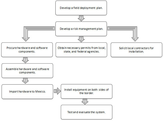
Developing a Field Deployment Plan
The implementation plan is meant to serve as a checklist for the activities that must take place after the detailed design is complete and before the procurement of equipment and software commences. This implementation plan could be amended if the specific characteristics of a POE necessitate it being changed. As noted previously, the implementation plan is not meant to replace the project management process or the systems engineering process.
Developing a Risk Management Plan
In following the project management process, risk management is addressed early in the project. However, risks need to be reevaluated prior to the major steps of equipment procurement and installation. Table 4 shows a sample risk management plan developed for the RFID implementations at BOTA and Pharr, Texas.
| Risk Type | Description of Impact | Mitigation Plans |
|---|---|---|
| Technology system costs increase significantly. | Unplanned procurement expense. | Check on costs and explore alternate sources if needed. |
| Integration of data from multiple sources proves to be problematic. | Unplanned labor expense. | Integrate data as realistically as possible during equipment checkout and table-top testing. |
| Reviews by stakeholder organizations take longer than expected. | Deliverables cannot be presented within their planned period of performance. | Monitor progress of responses from stakeholders. Implement work-around tactics as needed. |
| Managing numerous stakeholders including two different languages and two different countries proves to be more difficult than expected. | Unplanned management time, delays in agreements. | Work closely with key Federal-level and other influential stakeholders to resolve impasses that may arise. |
| Running the evaluation takes more resources than envisioned. | Unplanned labor and/or maintenance expense. | Identify and assess any unplanned challenges when discovered. |
| A real-world event occurs that elevates security at border crossings in a way that affects the technology implementation. | Reaction to the event delays installation due to security concerns or causes more limited data to be collected and key findings to be missed, resulting in non-optimal project recommendations. | Should any such event occur, work closely with FHWA, CBP, and other stakeholders to fully understand the impacts any such event has on the program’s technical integrity. |
| Vandalism takes installed equipment out of commission. | Interruption in data, delayed deliverables, and repair or replacement cost. | Maintain a security plan for the technology implementation, including stakeholder buy-in. |
Procuring Equipment
This step may involve getting quotes for system components, which may take a considerable amount of time. If possible, it is recommended to obtain quotes on system components earlier in the project so that time can be saved during this phase of the implementation plan. Receipt of RFID equipment may require 6 to 8 weeks after ordering.
Obtaining Necessary Permits from Stakeholder Agencies
Obtaining necessary permits from stakeholder agencies is a crucial step in moving the project forward toward installation. To obtain permits from the agencies in time without significant delay to the project, it is important that these agencies have favorable views about the project and that they are involved in every step of the project as key stakeholders. Table 5 includes a list of agencies that may have to be contacted to obtain permits, purpose of requesting a permit, conditions the agencies may put forth before granting the permit, and necessary documents requested by the agencies to review the permitting process. There needs to be sufficient lead time built in prior to installing the field devices to obtain necessary permits from these agencies.
It is possible that CBP representatives at a particular POE may require a compatibility test to ensure that the planned RFID implementation does not interfere with CBP’s equipment.
Soliciting Local Contractors for Installation
It is highly recommended that a local contractor that has experience with installation of utility poles and mast arms be used. Bringing in outside contractors requires more lead time and resources. Because the system has field devices in both the United States and Mexico, two separate contractors may be required to install the equipment—one on each side of the border. Local contractors from one country generally do not have permissions to go to another to install equipment in the field.
Assembling Equipment
Once the equipment is procured and in hand with the project team, all necessary preassembly can take place. All wiring between the readers, antennae, power sources, and cabinets (each of which need to be described in the final design document) needs to be performed at this point. In-house tests also need to be performed once the equipment is preassembled to ensure individual devices are working properly. This process helps reduce troubleshooting at the site.
An equipment list needs to have been generated in the final design document, and all identified products need to be procured in quantities to build the RFID reader stations with a central server. It is very unlikely that commercial-off-the-shelf (COTS) software is available to process the data inside the central server. Hence, custom application development needs to proceed at this point.
| Permitting Agency | Purpose of Requesting Permit | Conditions for Granting Necessary Permit | Documents to be Submitted to Obtain Permits |
|---|---|---|---|
| City, County, or State DOT from Both Sides of the Border | To install mast arms and poles on the right-of-way of these agencies. |
|
|
| CBP | To allow operation and maintenance of RFID reader stations inside the U.S. Federal compound. |
|
|
| GSA | To install RFID reader station inside the U.S. Federal compound. |
|
|
Importing Equipment to Mexico
Importing the equipment that is to be installed on the Mexican side of the border is a crucial element of the deployment process. Mexican laws require the use of a licensed Mexican customs broker to perform the importation into Mexico. The customs broker requires information on the make and model of the equipment and country of origin certificates in order to define the duties.
The approximate cost of importing the equipment is 15 percent of the total value. This could vary depending on the country of origin of the equipment. One possible option is to declare the sources of some equipment in Mexico, especially those that are also available in Mexico. This has to be verified from the manufacturer or retailer but reduces the cost of importing and the time it takes to prepare the paperwork.
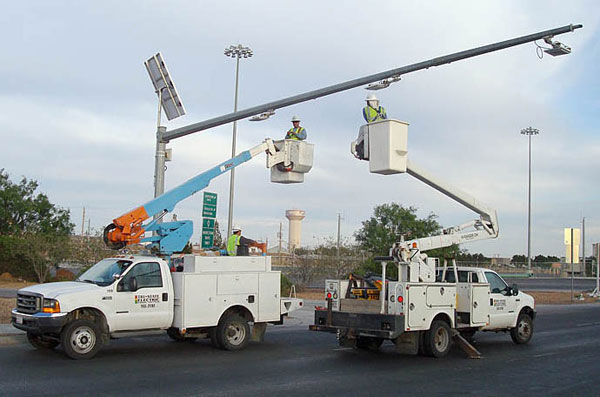
Installing Equipment
Once the equipment is assembled and local contractors are selected by the project team, onsite equipment installation can begin. Acceptance criteria need to be defined and agreed upon with the contractors, and authority to accept the installation should be established beforehand. Warranty terms and conditions need to be clear. It is important to note that while local contractors perform the actual installation work, members of the project team generally need to be present to supervise the work taking place onsite. Since land border crossings have many large vehicles moving about, safety is a key consideration. The project team and the contractors need to meet with the facility operators to discuss onsite safety considerations. Figure 10 shows installation of RFID antennae on a mast arm on the U.S. side of the BOTA crossing.
Testing and Evaluating the Installed System
After equipment installation, the tests documented in the T&E plan needs to be conducted. All the tests need to be successful, with no errors found in the way individual components of various subsystems operate.
Results of the tests and any problems completing the tests set forth in the T&E plan need to be documented and addressed at this point. If it becomes evident that the tests outlined in the T&E plan are not being met or exceeded, a process needs to be put in place to address and correct the problems with the system or redefine the key performance parameters if necessary.
The following sections briefly describe individual tests and evaluations recommended to ensure proper function of hardware and software components and the subsystems.
It is up to the implementing agency to decide whether to perform tests at all RFID reader stations or a selected few. If all the RFID reader stations are similar in terms of hardware and software used, it is not recommended to perform the tests at all stations.
Testing Field and Central Subsystems
Tests need to be performed to ensure that individual hardware and software devices are working properly. Also, tests need to be performed to ensure that software applications and communication links are taking place as intended.
Field subsystem tests include testing individual pieces of hardware installed in the field. Individual hardware pieces including RFID readers, antennae, solar power, and devices inside the cabinet have to be tested to ensure they are meeting their intended purpose. Many tests can be performed remotely, but some require actually opening the cabinet and reading display panels of the equipment. Table 6 includes a list of recommended tests to be performed with equipment installed as part of the field subsystem. Tests also depend on the configuration of hardware. For example, if the RFID reader station is being powered by a direct electricity source, then tests related to solar power and batteries are not necessary.
Appendix A includes steps to conduct the tests, parameters to be measured, and expected values (or ranges) to determine whether the hardware, software, and subsystems are functioning properly.
| Test | Purpose |
|---|---|
| Solar Power System Test | Verifies whether battery voltage, solar current, and load current readings are appropriate given the conditions at test time. |
| 24 vDC Power System Test | Verifies whether a proper voltage is applied to the RFID reader and programmable relay with both units connected and drawing power. |
| Tag Read Test | Verifies whether the RFID readers can recover an identification ID from the RFID tags used by the vehicles (i.e., read the tag). |
| Tag Reading Reliability Test | Verifies RFID reader’s ability to read at least 85% of the readable tags on trucks in lanes within the RFID unit’s coverage zone. |
| System Latency Test | Shows that all components that make up the field subsystem, once turned on, properly function together. |
| Data Logger Test | Verifies that the data logger in the RFID reader station can time stamp incoming tag reads from the RFID unit and locally store a copy of each tag read. |
| Wireless Signal Strength Test | Verifies sufficiency of cellular wireless signal strength. |
| Static IP Address Test | Verifies that the RFID reader station has a static (non-changing) IP address so the station can be found on the wireless network. |
| RFID Reader Station Communication Accessibility Test | Tests wireless router to ensure it can be accessed over the cellular wireless infrastructure. |
| RFID Reader Station Auto-Power Cycle Test | Tests the reader station’s ability to sense the loss of communication to the wireless network. |
| RFID Reader Shutdown Test | Tests whether the RFID reader can be automatically connected and disconnected to conserve power. |
Central subsystem tests include testing to ensure wireless data transfer between the RFID reader station and the central computer, retrieval of data from a data logger remotely, and ability of the software application that resides inside the central computer to retrieve data from the data loggers inside the RFID reader station. Table 7 includes a list of recommended tests to be performed with equipment and software applications that are part of the central subsystem.
| Test | Purpose |
|---|---|
| Wireless Data Transfer Test | The wireless router moves data from the output of the data logger (in pass-through mode) to a software application located at a central location. This test is designed to ensure that the data link between the logger and the central computer. |
| Remote Data Retrieval Test | The data logger can be accessed via the wireless network and Internet to retrieve data if a long-term communication outage has occurred. This test ensures that data can be retrieved from the data logger remotely. |
| Data Retrieval Application Test | RFID readers transmit the data through a wireless data modem to a central computer. A core application in the central computer retrieves data from data loggers at a predetermined time interval. This test is designed to ensure that the application does not fail completely in the event one or more RFID readers fail. |
Evaluating the System
The most important system test that must take place in order to assess the functionality and accuracy of the system is the system evaluation. Two key performance parameters are recommended in order to ensure the system accurately collects border crossing and wait times of trucks. These key performance parameters are:
Tag Read Time Stamp Accuracy: RFID readers send identification number of tags to a central server, which assigns a time stamp to each read. There are other RFID readers available on the market that assign a time stamp and send the data to a central server packaged with the identification of tags. In this case, there is no need for a central server to assign a time stamp. In any case, internal clocks of both RFID readers and the central server must be the same most of the time. These two times must be within 1 minute of each other 95 percent of the time in order to ensure the accuracy of the system. If there is a significant time delay between the RFID reader station and the central server, the time stamps of transponders will not be consistent. Thus, time difference between the readers and central processing system needs to be detected by pinging the router and recording the time delay (time required to send the data from the readers to the central server).
Accuracy of Crossing and Wait Times: A side-by-side comparison of crossing and wait time measured by the RFID-based border crossing time and wait time measurement system and the ones measured in the field (or baseline data) needs to be performed to evaluate the system. The difference between crossing and wait times collected by the RFID and the baseline data needs to be within 3 minutes of each other 85 percent of the time to guarantee the RFID-based border crossing time and wait time measurement system’s accuracy. There are several techniques by which baseline crossing and wait time data can be collected in the field. These techniques along with their pros and cons are described in Table 8.
The system evaluation may also consist of determining the ability of RFID readers to read a significant number of tags carried by the trucks crossing the border. Total tags read by the RFID readers can be compared with the total number of tags collected in the field by visually counting the tags carried by the trucks. However, as a word of caution, it is very difficult to accurately count the number of tags visually, since trucks carry many decals that appear to look like tags. Also, there is no way to confirm if the tag carried by a truck is active.
Appendix B includes steps to conduct an evaluation of the system and expected values (or ranges) to determine whether the system is accurately functioning.
| Technique | Pros | Cons |
|---|---|---|
| Recording video of trucks passing the RFID reader stations and manually re-identifying the license plate numbers. | Allows repeated post-processing of crossing and wait time data. Allows collection of other data such as volume, flow, type of trucks (with and without trailer) without requiring additional field personnel. |
May be perceived negatively by truckers due to their movement being video-taped. Needs additional time and resources to obtain crossing and wait time data. |
| Manually collecting license plate numbers of trucks passing the RFID reader stations and re-identifying the license plate numbers. | Needs less time and resources to obtain crossing and wait time data. | May be perceived negatively by truckers due to their movement being recorded. |
| Collecting location and time data from trucks installed with GPS devices. | Provides much finer location data of trucks than any other method. | Needs active participation by trucking companies, which may not be easy. Restricts sample size of trucks to the number of trucks fitted with GPS devices. Requires development of software application to obtain crossing and wait time data from the GPS data. |
| Using travel logs archived by carriers and shippers. | Eliminates the need for deploying surveyors in the field or purchasing GPS devices or GPS data from trucking companies. | Needs active participation by trucking companies, which may not be easy. Restricts sample size of trucks to the number of trucking companies agreeing to provide the log data. |
Monitoring and Troubleshooting the System
The system needs to be constantly monitored for proper operation using mechanisms that monitor the system at different time intervals. The system needs to be monitored to make sure all three subsystems are functioning properly and that communication between the subsystems is intact. System monitoring needs to be performed at predefined schedules and after special events such as extreme weather.
Monitoring of the system at predefined time intervals needs to be performed using a software application that checks for validity of the data stream and communication between subsystems and hardware devices. Automated monitoring using the software application can identify problems associated with communication failure due to hardware malfunction, inadequate wireless signal strength, or power failures. This application then needs to log all activities related to system checks and notify the system administrator immediately via e-mail or text message.
For example, an automated monitoring of systems in Pharr and El Paso is performed using a software application that runs periodically inside the central subsystem server. The software checks the status of communication between subsystems every 30 minutes. The software is pre-coded with bridge closing times. The software checks whether there have been any tags read in the last 30 minutes for each RFID station in the database; if so, then it is logged as a success. If the program does not find any tags when the bridge is supposed to be open, then the software performs a series of communication checks (e.g., by pinging the modem). If the software detects that the field subsystem is not online and/or if there are not enough tags being read, then an administrator is notified immediately via e-mail. The system design allows remote booting of the field devices, which may succeed in bringing the field devices online.
If power for the field devices or readers is being supplied by solar power, it is crucial to monitor the amount of electric charge the batteries are holding throughout the day. A software application cannot read the amount of charge the batteries are holding. One way to find out whether the system is getting enough power without actually visiting the field site is by analyzing the tag count. If there is not enough charge throughout the day, a graph of the number of tags read by the readers against the time of day needs to be created for several days, and trends need to be analyzed against the traffic pattern. If there is an inadequate power source, the number of tag counts might decrease significantly during evening hours, which might be contrary to the fact that large numbers of trucks are still crossing in the evening. In that case, voltage readings need to be confirmed by visiting the field site and reading the voltage off the battery controller.
It is also important to monitor the system after major weather events. Utility poles and mast arms are especially vulnerable to windy conditions. Readers, antennae, and communication devices are also vulnerable to extreme cold and hot temperatures. Flooding for a sustained period can damage batteries stored in an underground vault. The automated system can be programmed to monitor proper function of the system when extreme cold and hot temperatures are recorded by nearby weather stations, information that is released by the National Oceanic and Atmospheric Administration.
previous | next