Measuring Border Delay and Crossing Times at the U.S.–Mexico Border—Part II
Step-by-Step Guidelines for Implementing a Radio Frequency Identification (RFID) System to Measure Border Crossing and Wait Times
FEASIBILITY STUDY, CONOPS, AND SYSTEM REQUIREMENTS
Key Steps Prior to Designing the System
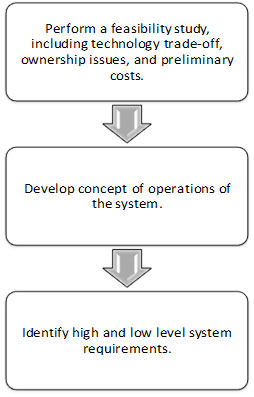
This section describes key planning-related steps to be undertaken by an implementing agency and/or the agency contracted by the implementing agency prior to developing high- and low-level designs of the system. These key steps identify alternative technologies and preliminary cost based on planning steps, identify stakeholder needs, and develop the concept of operations of the system. Eliciting stakeholder needs is probably the most important step and not only assists in defining the system but also in gaining support of the system. Key steps prior to designing the system are illustrated in Figure 5:
Performing a Feasibility Study
A feasibility study needs to be performed after stakeholders agree on the higher-level system concept, which mostly focuses on how the system is to be used. The feasibility study identifies institutional and financial constraints, appropriate technology, approximate costs, and scope of the system. The feasibility study reduces risk of cost and schedule overruns by verifying and identifying risks early on. Project feasibility is established once the project scope and cost estimations have been validated and verified against available agency resources and external funding. The feasibility study identifies the following:
- Alternative methods and technologies to achieve the same goals and objectives, such as use of existing infrastructure such as masts or cross-arms, hardwired vs. solar power, wireless vs. wired communications, and local vs. remote server.
- Project risks and institutional and physical constraints.
- Project and system cost, affordability, and funding sources considering the short- and long-term operation of the system.
Performing Technology Trade-Off Analysis
The preferred technology (in this case RFID) has proven its capability to measure, relay, and archive crossing and wait times of commercial vehicles. However, if the stakeholders have concerns about the fundamentally different alternatives to the RFID-based border crossing time and wait time measurement system, then a technology trade-off analysis needs to be performed to identify alternative technologies that could be less expensive and more acceptable to stakeholders. Thus, it is recommended that the implementing agency perform a technology trade-off analysis against the requirements of the stakeholders, funding availability, and operational characteristics of the border crossing. A trade-off analysis also helps to ensure that stakeholders are well-informed about strengths and weaknesses of alternative and preferred technologies.
An earlier trade-off analysis performed for the FHWA prior to deployment of RFID is an example of how similar studies can be performed by agencies. In the FHWA study, the following technologies were analyzed prior to selection of the RFID technology:
- Automatic vehicle identification (AVI):
- AVI using laser frequency.
- AVI using radio frequency (i.e., RFID).
- AVI using infrared frequency.
- Automatic vehicle location (AVL).
- Mobile phone location.
- Automatic license plate recognition (ALPR).
- Vehicle matching.
- Inductive loop detectors.
Factors such as cost, accuracy of readings, and maturity of technology, availability, and reliability were analyzed for each of the six main technologies listed above. Table 1 summarizes the results of the initial analysis from the study by listing the advantages and disadvantages of the six technologies.
| Technology | Advantages | Disadvantages |
|---|---|---|
| AVI |
|
|
| AVL |
|
|
| Mobile Phone Location |
|
|
| ALPR |
|
|
| Vehicle Matching |
|
|
| Loop Detectors |
|
|
Despite the advantages of the RFID technology, there are potential risks, which are as follows:
- Technology is susceptibility to damage.
- Equipment/components are susceptible to theft.
- Equipment has limited power sources.
- Data transfer is complex (especially from Mexican readers).
- Permits and agreements must be reached with public stakeholders.
Some other factors that can be considered while selecting RFID technology are as follows:
CBP (and DPS in the case of Texas) currently use RFID technology in its facilities. DPS installed several RFID reader stations inside its compound and distributed transponders to shippers and carriers on a voluntary basis. A high percentage of carriers whose vehicles cross the U.S.–Mexico border in Texas are outfitted with RFID tags in order to comply with CBP (and DPS) initiatives.
Because of substantial infrastructure investments by CBP (and DPS), it is understandable that RFID continues to be utilized in the long run at land border crossings along the U.S.–Mexico border.
Due to business competitive sensitivities, local private stakeholders tend to prefer technologies that are non-intrusive and do not have to reveal their operational practices, especially the shippers and carriers.
Prior to the pilot program for implementation of the RFID automated travel time measurement system at BOTA, it was emphasized to stakeholders that there was no intent for the RFID system to identify any carrier, truck, or driver. Rather, the interest was confined to gathering and manipulating aggregated data. The system was only intended to extract and time stamp the identification number of the transponder carried on a truck’s windshield. While there are other data that reside on the transponders, use of data beyond transponder ID is not necessary for travel time measurement. However, the possibility exists that the transponder ID number could be used for other purposes. For example, if the transponder ID were read at a remote sensor, it could be used to give a heads-up to Federal Motor Carrier Safety Administration (FMCSA) and/or State vehicle inspectors that a certain truck was inbound because the transponder ID presumably is in their databases. Truck drivers are naturally curious about what data are being collected as they drive past RFID equipment some distance from the border. It needs to be made clear to stakeholders exactly what data are to be collected and for what purposes they are to be used.
Identifying Ownership Issues
There needs to be a clear distinction between who owns and who operates the RFID-based border crossing time and wait time measurement system after it is deployed. This may depend on the type of procurement method used, especially in the case of design-build type procurement in which the institution contracted to maintain the system may be designated as the owner of the system until the system has been transferred to a government agency as the owner. If the procurement method is not a design-build arrangement, then the implementing agency is the owner of the system but could contract with another institution for operating and maintaining the system.
Liability issues need to be identified, addressed, and completely understood early on. It is strongly recommended to pursue services of legal experts to assess the likely impact of liability.[5] It is also important in the case of a cross-border project, such as is being described in this document, to identify who is liable for damages due to equipment failures in Mexico.
Also, data ownership and redistribution might emerge as an issue for which adequate policies and procedures need to be in place. If the region already has other ITS deployments, then such policies can be borrowed from previous projects. In most situations, policies regarding distribution of data are governed by Federal, State, and city laws if the owner of the system is a public agency.
It must be clear who owns the intellectual property rights that might result from the deployment. Retaining intellectual property rights also depends on source of funding. Typically, Federal funding sources allow private entities contracted to implement the system to retain rights and patents generated by the system.
Data ownership, redistribution, and intellectual property rights issues also need to be specified in contractual documents developed prior to procurement of private entities and contractors to design and deploy the system.
Estimating Preliminary Costs
At this stage of the project planning, it is important to estimate the approximate cost of deploying an RFID-based border crossing time and wait time measurement system. However, the cost needs to reflect the following three key drivers of the project and the system: major hardware components, high-level capabilities, and O&M needs.
There are no formal sources whereby the implementing agency can reliably estimate the approximate cost. Studies have used the FHWA ITS Cost/Benefits Database to estimate ITS deployment cost, but the database has not had enough unit cost history to estimate the cost of components for an RFID-based border crossing time and wait time measurement. Hence, the ideal method of estimating preliminary project and system cost is by referring to past projects with similar scope and capabilities (i.e., analogous estimating). FHWA and TxDOT have procured similar projects and are deploying more at the U.S.–Mexico border. The actual cost of these projects is a reliable source with which to estimate preliminary project costs.
Table 2 includes the cost of RFID-based border crossing time and wait time measurement system projects deployed at various crossings at the U.S.–Mexico border. All project costs include cost of major hardware components, management labor, field device installation, and O&M.
| Project Location | Project Sponsor | Project Cost | Equipment and Installation Direct Cost | RFID Configurationa |
|---|---|---|---|---|
| Bridge of the Americas, El Paso, Texas | FHWA | $328Kb | $110,000 | 2 reader stations, 2 with solar power, 5 traffic lanes |
| Pharr-Reynosa Bridge, Pharr, Texas | TxDOT | $213Kc | $70,000 | 4 reader stations, 1 with solar power, 9 traffic lanes |
| World Trade Bridge and Colombia Bridge, Laredo, Texas | TxDOT | $408Kd | $170,000 | 6 reader stations, 2 with solar power, 21 traffic lanes |
| Veteran’s Memorial Bridge, Brownsville, Texas | TxDOT | $248Ke | $100,000 | 3 reader stations, 1 with solar power, 8 traffic lanes |
| Mariposa Port of Entry, Arizona | ADOT | $180Kf | $56,000 | 2 reader stations with solar power, 4 traffic lanes |
a Reader configuration includes reader stations, readers, and antennae. Reader stations are physical locations where there is infrastructure including one or more RFID readers, each connected to antennae on a mast or roadway cross-arm, equipment cabinet, batteries, wireless modem (typically), and solar power (if there is no reliable hardwire power available). Reader configuration in Table 2 includes total number of individual RFID reader stations located on both sides of the U.S.–Mexico border. A single RFID reader is capable of receiving information from multiple antennae located over passing vehicles. Each antenna typically reads transponders from a single lane, so the number of traffic lanes shown for a crossing in Table 2 corresponds to the number of antennae deployed. ↑
b As a pilot deployment, along with installation and evaluation/assessment of results, this project included costs for:
- Coordinating stakeholders.
- Gathering baseline data.
- Identifying potential vehicle detection technologies and conducting a trade-off analysis.
- Developing requirements, specifications, and ConOps.
- Designing the project.
- Developing implementation plan.
- Demonstrating technology effectiveness.
- Reporting (including Section 508 compliance). ↑
c This project included two reader stations in Mexico and two in the United States. ↑
d This project included two crossings. Readers were installed at the CBP primary inspection booths and cover a total of 12 lanes—8 at the World Trade Bridge and 4 at Colombia. ↑
e This project included installation of readers at CBP primary inspection booths, covering four lanes. ↑
f While two reader stations (one on each side of the border) are in the original plan, two reader stations are now planned for the Mexican side of the border and one at CBP primary inspection booths due to stakeholder input and POE layout, which is expanding to eight lanes. ↑
Based on the estimated and actual cost of past RFID-based border crossing time and wait time measurement system projects listed in table 2, the approximate cost of such a system ranges between $70,000 to $100,000 per RFID reader station. Per-station cost includes the following:
- The reader station includes a single utility pole with a mast arm, concrete foundation, and battery vault installed without acquiring the right-of-way.
- Accessories include a solar panel, signal cabinet, and necessary panel board to hold communication and power devices.
- RFID components include two antennae per reader and four antennae per mast arm.
- The central subsystem includes storage space on an existing database server and a relational database structure to archive and process the crossing and wait time data.
- The user subsystem includes storage space in a Web server to host a map-based Web site to relay current crossing and wait time using real simple syndication (RSS) and a set of predefined charts and graphs.
The bulk of the per-station cost includes installation of a separate utility pole and the mast arm, the cost of which is approximately $30,000. Note that the cost of installation both on the U.S. and Mexico side may not differ substantially. If an existing mast or gantry is available to install the RFID readers and antennae, then the per-station cost can be reduced by almost 50 percent. The aforementioned project cost also includes approximately $550 to $650 per month per reader station to operate and maintain the system for a 12-month period.
Developing a Concept of Operations
The ConOps sets a framework for the design and deployment of the system and a technical course for the project.[1] Its purpose is to clearly convey a high-level view of the system to be developed that each stakeholder can understand. The ConOps is not a document that lists the detailed requirements for the system, nor is it a design document that specifies the technical design or technologies to be used. The ConOps defines the following:
- What the stakeholder needs are and stakeholders’ roles and responsibilities in the project.
- What the high-level capabilities of the system are and its basic elements.
- What the ideal locations of RFID reader stations are.
- How the system is to be evaluated and validated (key performance parameters [KPPs] or other measures).
- How the system is to be operated and maintained.
Defining Stakeholder Needs and Their Responsibilities
There are several stakeholder agencies involved in the border crossing process for commercial trucks crossing the U.S.–Mexico border. One or more stakeholder meetings need to be undertaken to (a) solicit stakeholder participation during the project, (b) identify stakeholder needs, and (c) identify responsibilities of individual stakeholders throughout the life cycle of the project. Active participation and support from these agencies depends on their immediate need for the border crossing and wait time data. It is important to note that not all agencies may play an active role in the project, but their involvement might be crucial in successful deployment of the system. Thus, discussions aimed at addressing any stakeholder questions and/or concerns about the technology and the system need to be encouraged and facilitated. For example, stakeholder agencies that have to issue permits to install equipment in their right-of-way may understandably have initial concerns about the technology and equipment being deployed so that it does not hinder their operations.
A list of stakeholder agencies, including their points of contact for the project, need to be developed early in the project. Typically, for a cross-border project of this type that involves components being deployed in two different countries, stakeholder agencies most likely include:
- U.S. Federal agencies:
- CBP.
- General Services Administration (GSA).
- FHWA.
- FMCSA.
- U.S. Environmental Protection Agency (EPA).
- U.S. State-level agencies:
- DPS, State Highway Patrol.
- State DOTs.
- Mexican Federal agencies:
- Aduanas.
- Secretaría de Comunicaciones y Transportes (SCT).
- General Services Administration.
- Mexican local and regional stakeholders:
- MPOs.
- Cities and States.
- Mexican private stakeholders:
- Maquila associations.
- Shippers and carriers.
- Local transportation service providers.
- U.S. local and regional stakeholders:
- MPOs, councils of government, associations of government.
- Cities and counties.
Table 3 includes roles and responsibilities of key stakeholder agencies in successfully deploying an RFID-based border crossing and wait time measurement system on the U.S.–Mexico border.
| Stakeholder Agency | Roles and Responsibilities in Deploying a RFID-Based Border Crossing Time and Wait Time Measurement System |
|---|---|
| GSA | The Federal inspection facility on the U.S. side is owned by the GSA. Installation of RFID equipment under the auspices of FHWA requires approval of GSA form 1583: Permit for Use of Real Property by Federal Agency. |
| CBP | CBP coordinates with GSA to allow the installation of RFID equipment. In the past, CBP has shown interest in receiving most current wait times and crossing times. |
| FHWA, State DOTs, Cities, and MPOs | These agencies may play a major role as a funding and/or implementing agency and provide right-of-way and access to existing roadside infrastructure. |
| Freight Carriers and Shippers | These agencies help define requirements of the system for real-time information and archived data based on their needs. |
| Mexican Local, State, and Federal Agencies | Local and State agencies play a significant role in providing the necessary right-of-way, which may also belong to Federal agencies. They may also assist in lowering the equipment importation. |
Based on experiences from similar projects, stakeholders particularly indicated a need for efficient and reliable traveler information related to border crossings. Also, archived border crossing data are used by private and public agencies that have responsibilities to plan, operate, and manage border crossing infrastructure. Archived data are used by agencies such as MPOs, city agencies, CBP, and GSA to plan future infrastructure improvements and manage resources in order to operate border crossings efficiently.
Identifying the Ideal Location for RFID Reader Stations
All border crossings are different in their operational characteristics. Differences in features such as physical layout, hours of operation, provision of separate lanes for shipment types, and expedited processing arrangements influence system design. Thus, developing a geometric layout of a border crossing is essential. At large crossings and most other crossings, lanes for passenger vehicles and trucks typically separate prior to the crossing and converge after departure from the crossing.
A footprint of a border crossing typically needs to consist of the following:
- Physical boundaries of State and Federal inspection facilities.
- Path of trucks from start of queue to exit of the State facility.
- Separate paths for shipment types, primary and secondary inspections.
- Identification of access and egress for trucks to access facilities other than inspection facilities.
- Egress points that could allow trucks to depart the truck path after being detected by entry but not exit reader(s).
- Right-of-way along the truck path.
- Tentative location of RFID reader stations.
A typical footprint of U.S.–Mexico border crossings in terms of freight movement consists of the following:
Mexican export lot—A facility operated by Mexican customs that is responsible for inspecting export materials leaving Mexico. Generally, only a small percentage of freight is physically inspected at this facility. Roads leading to the Mexican customs facility may be a Federal roadway or a city roadway. At many border crossings, roadways leading to the facility could be on the right-of-way of a city and Federal agency. Thus, permission from the city and SCT is essential to install field devices on the right-of-way.
U.S. Federal inspection compound—This facility is operated by CBP. Its primary function is to make sure no illegal freight is permitted to enter the United States. Secondary inspections can occur here if CBP feels it necessary to further examine the driver, freight, or conveyance. These secondary inspections can include intrusive measures (e.g., physically unloading the trailer to examine its cargo) or non-intrusive measures (e.g., x-ray or gamma ray imaging). FMCSA might be co-located within the facility. CBP is the occupant of the facility, but GSA is responsible for all construction-related activities inside the compound. Hence, obtaining necessary permits from GSA is essential to install field devices inside the facility.
State inspection facility—This facility is operated by the State’s Department of Public Safety. Its primary function is to ensure that tractors and trailers entering the United States from Mexico are safe enough to operate on U.S. roadways. Secondary inspections of the vehicles can occur here if deficiencies are revealed through a preliminarily review of the conveyance by DPS. In the State of Texas, the inspection facility is located on TxDOT’s property and right-of-way. Hence, obtaining TxDOT’s permission to install utility poles for the readers on the side of the road north of a facility in Texas is necessary. This may not be the case with other States.
The northbound commercial freight border crossing process begins at the Mexican export lot on the Mexican side of the border (also known as the Aduana facility). After clearing customs on the Mexican side, a truck crosses into the United States, typically across a physical bridge structure. Immediately upon entering the United States, the truck proceeds to the U.S. Federal inspection compound. Entrance to the Federal inspection compound is accessed through a primary inspection booth. At these primary inspection booths, a CBP agent determines whether the truck requires any secondary inspection. If so, the agent directs the driver to it; otherwise, the agent instructs the driver to simply proceed to the exit. Final clearance to depart the Federal inspection compound is given at a booth at the exit of the compound, at which point the truck enters a State inspection facility (in Texas, the BSIF).
In principle, the greater number of RFID reader stations that can be installed at a border crossing, the greater the ability to segment the truck path in a way that yields information on where delays are occurring. The more detailed information facilitates both a more effective response to alleviate congestion and better historical data about the causes of the congestion. However, more readers means more cost. The benefits of segmenting the truck path with more readers needs to be discussed with stakeholders so that they are clear on the trade-offs. In reality, it may be difficult to secure a budget for more than the basic two or three readers. As an illustration, the approximate locations for potential measuring sites identified for the BOTA border crossing site were as follows:
- R1—the farthest point from the entrance to the Mexican export lot, before the queue develops on the Mexican side of the border.
- R2—the entrance to the Mexican export lot.
- R3—the exit of the Mexican export lot.
- R4—primary inspection booth of the U.S. Federal compound.
- R5—the entrance to the State inspection facility.
- R6—the end of the border crossing process after the exit of the State inspection facility.
Based on these sites, the respective segments allow measurement of the following:
- R1 to R2—the amount of time a truck spends in the queue on the Mexican side of the border.
- R2 to R3—the amount of time a truck spends in the Mexican export lot.
- R3 to R4—the amount of time a truck spends on the physical bridge before entering the U.S. Federal compound.
- R4 to R5—the amount of time a truck spends inside the U.S. Federal compound.
- R5 to R6—the amount of time a truck spends inside the State inspection facility compound.
- R1 to R4—wait time of a truck, assuming the time spent to enter the Mexican facility is relatively small if the truck is a FAST one or zero in the case of a non-FAST truck.
- R1 to R6—crossing time of a truck to complete the border crossing process.
Two reader stations corresponding to R1 and R6 were initially implemented at BOTA to provide measurement of crossing time, and a third reader station corresponding to R4 was installed that provided measurement of wait time.
Defining High-Level Capabilities of the System
Through stakeholder meetings, high-level capabilities of the proposed system need to be defined. All the stakeholders need to be in agreement with these capabilities, which need to satisfy their individual needs. High-level capabilities of the system need to be short and concise. An example list of high-level capabilities for an RFID-based border crossing time and wait time measurement system includes the following:
- The system needs to automatically measure the wait time required for a northbound truck to move from a predetermined point upstream of the typical queue on the Mexican side to the CBP primary inspection facility on the U.S. side.
- The system needs to automatically measure the crossing time required for a northbound truck to move from a predetermined point upstream of the typical queue on the Mexican side to the exit of the POE on the U.S. side.
- The system needs to relay most recent crossing and wait times to local media and travelers through the Internet and other electronic delivery mechanisms.
- The system needs to systematically archive all the raw crossing and wait time data created during the course of the RFID implementation.
- Archived data need to be made available to authorized subscribers and stakeholders.
Defining Evaluation Performance Measures
The ConOps also needs to define the approach that is to be taken to evaluate and validate the system and the project. Key performance measures and a basic plan to evaluate and validate the system need to be included in the ConOps. All the stakeholders need to be in agreement with these key performance measures.
After the system has been installed, it needs to be tested and evaluated based on a test and evaluation (T&E) plan that is developed as part of a detailed design. The T&E plan is based on the performance measures identified in the ConOps.
Two key performance measures are recommended in order to ensure that the system accurately collects border crossing and wait times of trucks. These key performance measures are:
Tag Read Time Stamp Accuracy: RFID readers send identification number of tags to a central server, which assigns a time stamp to each read. Internal clocks of both RFID readers and the central server must be the same most of the time. These two times must be within 1 minute of each other 95 percent of the time in order to ensure the accuracy of the system. If there is a significant time delay between the RFID reader station and the central server, the time stamps of transponders will not be consistent.
Accuracy of Crossing and Wait Times: A side-by-side comparison of crossing and wait time measured by the RFID-based border crossing time and wait time measurement system and the one measured in the field (or baseline data) need to be performed to evaluate the system. The difference between crossing and wait times collected by an RFID-based border crossing time and wait time measurement system and the baseline data need to be within 3 minutes of each other 85 percent of the time to guarantee the RFID-based border crossing time and wait time measurement system’s accuracy. There are several techniques by which baseline crossing and wait time data can be collected in the field.
The system evaluation may also consist of determining the ability of RFID readers to read a significant number of tags carried by the trucks crossing the border. Total tags read by the RFID readers can be compared with the total number of tags collected in the field by visually counting the tags carried by the trucks. However, as a word of caution, it is very difficult to accurately count the number of tags visually since trucks carry many decals that appear to look like tags. Also, there is no way to confirm whether the tag carried by a truck is active.
Identifying System Requirements
System requirements describe what the system needs to do to meet the stakeholder needs. Developing system requirements could be an iterative process in some projects and may involve going back and forth among the stakeholders to come up with a final list of requirements. It is important to involve stakeholders in requirement development. Stakeholders may not have experience in writing requirement statements, but they are the foremost experts concerning their own requirements.
The following is a sample list of system requirements:
- The system must not interfere in any way with day-to-day operations at the border crossings. The process of vehicle detection should not impact the speed or path of vehicles through the facilities.
- The system must not require the interaction of either drivers or employees of agencies manning the POE on either side of the border during normal operation, other than to report on a visible anomaly such as damaged system hardware (e.g., a tag reader antenna).
- System failure must not affect operations at the POE.
- The system must be focused on analysis of aggregated data rather than the identity of drivers, shipments, or trucks in order to maintain anonymity. The goal is to generate average crossing and wait times from individual vehicle data and not to specifically track and store crossing and wait times of individual vehicles.
- Processed crossing and wait time data need to be available to authorized subscribers through the Internet.
- If more than two RFID reader stations are installed, segmented data need to be obtained, measured, and archived.
- The system need not require an interface to any current equipment or data streams in use at the POE. The system need not rely on data from other parties to be effective, although data from these parties may be incorporated at some point to increase the overall value of the project.
- Commercial vehicles are expected to have RFID tags using either the TransCore eGo or American Trucking Association’s (ATA’s) tag protocol. The field tag reader equipment is to be able to read tags of either protocol.
- The RFID reader station design needs to include a solar-powered option (including batteries) to support deployment in a more remote area or an area with unreliable electrical service.
- The RFID reader stations need to be capable of maintaining an accurate time clock, at least accurate to the minute, for use in time-stamping tag reads. Other approaches that can maintain time synchronization are also acceptable.
- All field equipment must exhibit sufficient environmental specifications to ensure proper operation in the area climate.
- The RFID reader station design needs to incorporate a method to detect malfunctioning equipment, send an alert, and attempt to self-correct or otherwise compensate for the problem. This is particularly necessary for the communication link.
- The design of the system needs to maximize the use of off-the-shelf components that can be readily purchased in case a repair is required.
- The RFID reader station design needs to be such that little ongoing maintenance is required since the sites may be difficult to access without prior authorization.
Evaluation Questionnaire
The implementing agency should prepare a list of questionnaire that should be considered prior to designing the system and ensure that the system is feasible. A recommended list of evaluation questionnaire is as following:
- Have you identified the stakeholders for the system?
- Have all the stakeholders agreed to support and participate in the project for a successful deployment?
- Have you identified and defined institutional issues of ownership and liabilities?
- Have you performed technology trade-off studies? Are there any other technologies that the stakeholders prefer?
- Have you determined approximate cost for installing and maintaining the system? Can you afford the system and obtain funding?
- Have you defined high-level capabilities of the system?
- Have you identified requirements for the system?
- Are there any requirements that cannot be met by the system? Are these requirements critical, or can they be met by incremental upgrades to the system in the future?
- Have you identified how the system will be evaluated and validated?