5. Interfacing with the FHP CAD System
One source of statewide traffic-related information developed by iFlorida was an interface to the Florida Highway Patrol Computer Aided Dispatch (FHP CAD) system. Three different tools were used by the Florida Department of Transportation (FDOT) to interface with the FHP CAD system. The first tool "pushed" incident information to the Condition Reporting System (CRS). When the CRS failed, FDOT funded a project to develop a new interface to the FHP CAD data that would filter the data and make it available to FDOT Regional Traffic Management Center (RTMC) operators via a FHP CAD Data Viewer Web site. This was intended to be an interim solution until SunGuide, the replacement for the CRS software, could interface with the FHP CAD system. As this report was being written, the FHP CAD interface to SunGuide was being developed, based on the FHP CAD interface to the FHP CAD Data Viewer.
5.1. The FHP CAD System
The FHP operates seven installations of its FHP CAD, one for each of the nine FHP Dispatch Centers. These seven dispatch centers support the nine FDOT districts and the Florida Turnpike. FHP duty officers enter data into these CAD systems as incident information is received, and update the incident data as new information arrives. Each of these installations of the FHP CAD system submits data to a separate FHP server for inter-agency sharing and to support the FHP Traffic Crash Report Web site. Figure 48 is a screen shot taken from that Web site.
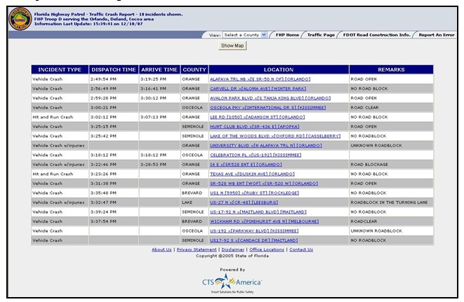
Figure 48. The FHP Traffic Crash Report Web site
FDOT identified five types of data within the FHP CAD system that could be useful, and FHP provided insights into these types of data and their availability and reliability.
| A process must be in place to update incident type translation tables whenever incident types are changed on the CAD side of a CAD-DOT interface. |
- Latitude and longitude. In Florida, the data is usually present and reliable. (FDOT reviewed one week of FHP-CAD data and verified that the latitude-longitude data was very reliable.)
- Incident type. This data is always present, though the incident type categories used by FHP are different than those used by FDOT. The FHP CAD side of the interface translates the FHP incident types into ones recognized by FDOT. Since FHP changes the incident types periodically, a process is needed to ensure that the translation tables are updated whenever FHP makes changes to the incident types.
- Road location. When the FHP CAD interface was first used, this information was not always entered into the correct fields-it might be placed in a free text description field rather than in the road location fields. FHP sent out memos and took other steps to improve the consistency of how data was entered into the CAD system. Currently, this data is almost always present and in the correct field.
- The incident description is free text and includes many inconsistencies in the format and content of the data.
- County. The county field is not currently populated in the data received by FDOT. FHP will be updating FHP CAD to address this issue. In the updated version, county data will be added before warehousing the data, based on the latitude and longitude of the event.
| The DOT should work with the Highway Patrol to ensure that practices are in place to enter key information in the correct fields within the CAD system. |
5.2. The FHP CAD Interface to CRS
The CRS used FHP CAD data as one source of incident information, integrating it with incident information that could be directly entered by RTMC operators. Figure 49 depicts this CRS user interface for reviewing FHP CAD data.
The user interface displayed a list of incidents that the CRS had successfully received from FHP CAD and allowed users either to accept an incident (i.e., integrate the incident with other CRS incidents and continue to update it as new information arrived from the FHP CAD), take over an incident (i.e., integrate it with other CRS incidents and customize the information, but no longer update it if new information arrived), delete it, and place it on hold (i.e., decide later how to process the incident).
The FHP CAD interface to CRS was implemented as follows:
- FDOT hired the FHP CAD contractor (CTS America) to work with the CRS contractor to develop the interface between these two systems.
- The CRS contractor developed an interface specification based on the IEEE 1512 standards and provided that specification to the FHP CAD contractor.
- The FHP CAD contractor developed software to support its side of the interface to present data according to the specification provided by the CRS contractor, and the CRS contractor developed software to support the CRS side of this interface, along with CRS tools to manage incident information that was received.
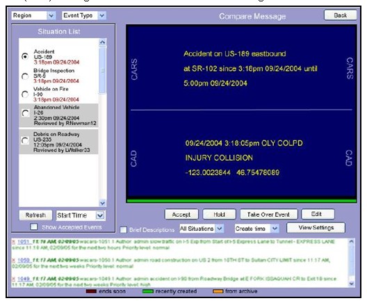
Figure 49. The CRS Interface to FHP CAD Data
The basic approach was to use Simple Object Access Protocol (SOAP) for transmitting incident information with the XML message formats based on the IEEE 1512 standards. Three types of messages were defined:
- New Incident. Information about a new incident is transmitted via the 1512 Incident Description (IDX) message with the Status Indicator indicating the information is for a new incident. This message defines an Event ID, which is a unique identifier that is used to identify an event in all additional messages related to that incident.
- Incident Update. Information about an already defined incident via the 1512 Incident Description (IDX) message with the Status Indicator communicating that the information is for an already defined incident (i.e., a New Incident message had already been sent).
- Close Incident. An incident is closed when the FHP CAD system transmits a "close incident event" message.
The CRS contractor took the message format itself directly from the IEEE 1512 standard in the form of a set of 13 ASN.1 statements, which the FHP CAD contractor was expected to convert to XML.
| The use of event-driven messages requires implementation of methods to identify and recover from dropped events. |
The messages would be transmitted from the FHP CAD system to the CRS via a SOAP push transfer. The CRS contractor referred to this as "event-driven SOAP" because each transfer was related to an event that occurred within the FHP CAD system: defining a new incident, updating an existing incident, or closing an existing incident. One consequence of using event-driven messaging is that the process must define methods for identifying and recovering when a dropped event occurs. This could occur for any of several reasons, including failure of the FHP CAD server (i.e., a set of event messages due for transmission was not sent), network failure (i.e., so a sent message was not received) or failure of the CRS (i.e., a received message was not processed). If a message is dropped, a problem will occur with the CRS side of the data. If a New Incident or Incident Update message is dropped, incident data will be missing from the CRS. If a Close Incident message is dropped, a message will exist in CRS after it has been closed within the FHP CAD system.
The interface did include data for detecting when a message was dropped. The 1512 standard includes an Update Counter in the 1512 messages, and the CRS contractor required that the FHP CAD messages include this counter. This counter could be used to identify a dropped message by comparing the Update Counter with the last received Update Counter for an incident. This could detect dropped New Incident and Incident Update messages, but not a dropped Close Incident message.
The interface also did not include an approach for notifying the FHP CAD system that a message had been dropped and should be resent. In fact, the CRS design document does not indicate that the CRS will detect and recover from dropped FHP CAD messages, nor does it state how it will recover and restart if the CRS fails. There was evidence of these omissions in the data archived from the CRS, in that a query of recent incidents would often include older incidents that had never been closed.
| Identify the fields for which the CAD system does not perform strong quality control checks. Those fields may require extra effort to use them within a DOT system. |
Other problems occurred after the CRS received the data. First, the CRS often had difficulty correctly identifying the location at which an incident occurred. Within the CRS, the road and milepoint location were key to locating the incident. Within the FHP CAD system, this type of location information was not needed internal to the software. Consequently, a variety of road names might be used for the same road and, when the FHP CAD interface was first used, the road name might be entered as part of the free text description rather than in the correct field. This made it difficult for CRS to use the road name to locate incidents.
Since the latitude and longitude of FHP CAD incidents were present and reliable, the CRS used those values to identify the road location for an incident by "snapping" an incident to the point on the CRS road network that most closely matched the incident latitude and longitude. Incidents that were not located near any CRS road would be discarded. Unfortunately, the CRS incident snapping process did not work reliably, as incidents would sometimes snap to locations far removed from their actual locations. When incident snapping was turned off, a new problem occurred: the CRS could no longer filter out incidents that were not located on CRS roads, and RTMC operators had to delete a large number of extraneous FHP CAD incident data.
This combination of problems severely limited the usefulness of the CRS implementation of the FHP CAD interface.
5.3. The FHP CAD Interface to the FHP Data Viewer
The FHP Data Viewer Web site was designed to obtain incident information from the FHP CAD system, identify the road on which each incident occurred, and provide an interface that would allow RTMC operators to easily review incidents for each road that was covered by the Central Florida or Statewide 511 systems. Organizing the data by road was intended to make it easier for RTMC operators to maintain the road-based 511 messages. The organization of the incident data in the FHP Data Viewer is shown in Figure 50.
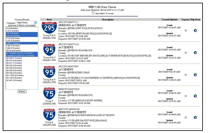
Figure 50. The FHP Data Viewer Web site
Rather than adopting the IEEE 1512 standard directly for the FHP CAD interface to the FHP Data Viewer, this standard was used as a starting point and was modified through a collaborative effort between CTS America (the FHP CAD vendor) and PBS&J (the FDOT contractor developing the FHP Data Viewer Web site). They first considered using the CRS 1512-based interface, but decided it was too complex. A simpler interface was designed that used file transfer protocol to push incident information from the FHP CAD system to a PBS&J server (rather than SOAP) and provided complete information from every active incident with each update (rather than using event-driven messages).
One advantage of this approach was that it was not subject to errors related to dropped messages. The main disadvantage was that the amount of information transmitted was larger. Since a typical FHP CAD incident message was less than 1 KB and the FHP CAD system typically was handling fewer then 200 incidents at a time, the size of the resulting XML file was small enough that the resending incident data would have a very minor impact on system performance.
Another advantage was the simplicity of the interface. Whereas the interface to the CRS was developed over a period of several months, the total time to design the interface and develop the software to support the FHP CAD side of the interface was about two weeks. It took about two weeks longer to finish the initial development of the FDOT side of the interface and the FHP Data Viewer.
To overcome the limitation experienced by the CRS with regard to road names, the developers of the FHP Data Viewer used a translation table to convert road names received by FHP into standard road names used by FDOT. For example, the Florida Turnpike is referred to by a number of names, including "SR 91" and the "Florida Turnpike." PBS&J reviewed archived FHP incident data to identify commonly occurring road names and translated them into the unique names used for roads within the FHP Data Viewer.
RTMC operators believed that the FHP Data Viewer Web site did provide a reliable source of incident data from the FHP CAD system, and many used it as their primary source of incident information. Some still preferred using the FHP Web site directly.
5.4. Summary and Conclusions
The primary objectives of the various FDOT interfaces to the FHP CAD system were to provide RTMC operators with an improved source of FHP incident information, which they could use to support the Central Florida and Statewide 511 systems. The first version of this interface was not very successful, and many operators preferred to refer to the incident information available via the FHP Traffic Crash Reporting Web site rather than rely on the CRS to provide incident information. The second version of this interface (the FHP Data Viewer), however, was successful.
While deploying and operating these systems, FDOT did identify a number of lessons learned that other locales may find useful.
- The DOT should work with the Highway Patrol to ensure that practices are in place to enter key information needed by the DOT in the correct fields within the CAD system. The data needs of FHP were different from those of FDOT, so some data fields that were key to FDOT but not key to FHP were not always entered consistently. One example was the road name, which was sometimes entered in the FHP CAD system as part of the free text description rather than in the road name field. FHP cooperated closely with FDOT by encouraging its dispatchers to follow more stringent data entry requirements with respect to these fields.
- Transferring data from the FHP CAD system required translation of some coded values from FHP's values to those recognized by FDOT. An example was the incident type. Because FHP sometimes revised the list of acceptable values for incident types and their meanings, FHP instituted procedures to ensure that the tables used to translate FHP incident type values to FDOT values would be updated whenever such changes occurred.
- Event-driven messaging is subject to errors related to dropped messages. A system that uses event-driven messaging should include methods for identifying and recovering from dropped messages.