Traffic Signal Timing Manual
Contact Information: Operations Feedback at OperationsFeedback@dot.gov
This publication is an archived publication and replaced with the Signal Timing Manual - Second Edition.
CHAPTER 4
TRAFFIC SIGNAL DESIGN
TABLE OF CONTENTS
- 4.0 TRAFFIC SIGNAL DESIGN CONCEPTS
- 4.1 Overview
- 4.1.1 Relationship between Signal Timing and Traffic Control Design
- 4.1.2 Traffic Signal System Design
- 4.2 Phasing Overview
- 4.2.1 Definitions and Terminology
- 4.2.2 Ring-and-Barrier Diagrams
- 4.3 Left-Turn Display Options
- 4.3.1 Permissive Only Left-Turn Phasing
- 4.3.2 Protected Only Left-Turn Phasing
- 4.3.3 Protected-Permissive Left-Turn Phasing
- 4.3.4 Split Phasing
- 4.3.5 Prohibition of Left-Turns as a Phasing Option
- 4.3.6 Guidelines for Selecting Left-Turn Phasing
- 4.4 Left-Turn Phase Sequence Options
- 4.4.1 Lead-Lead Left-Turn Phase Sequence
- 4.4.2 Lag-Lag Left-Turn Phase Sequence
- 4.4.3 Lead-Lag Left-Turn Phase Sequence
- 4.5 Pedestrian Phasing
- 4.6 Right-Turn Phasing
- 4.7 Detection Fundamentals
- 4.7.1 Detection Design Objectives
- 4.7.2 Detector Operating Modes
- 4.7.3 Controller Memory Modes
- 4.7.4 Detection Design for High-Speed Approaches
- 4.7.5 Detection Design for Low-Speed Traffic Movements
- 4.8 Detection Applications
- 4.8.1 Basic Fully-Actuated Design
- 4.8.2 Volume-Density Design
- 4.8.3 Multiple-Detector Design
- 4.8.4 Left-Turn Movements
- 4.8.5 Right-Turn Movements
- 4.9 References
LIST OF TABLES
- Table 4-1 Recommended distance between stop line and detector
- Table 4-2 Recommended detector locations and timing settings for multiple detector technique
LIST OF FIGURES
- Figure 4-1 Physical components of a signal system
- Figure 4-2 Phasing and movement diagram for the intersection of two one-way streets
- Figure 4-3 Typical vehicular and pedestrian movements at a four-leg intersection
- Figure 4-4 Standard ring-and-barrier diagram
- Figure 4-5 Ring-and-barrier diagram for intersection of two one-way streets
- Figure 4-6 Ring-and-barrier diagram showing permissive phasing
- Figure 4-7 Ring-and-barrier diagram showing protected phasing
- Figure 4-8 Ring-and-barrier diagram showing protected-permissive phasing
- Figure 4-9 Ring-and-barrier diagram showing split phasing
- Figure 4-10 Prohibited left turns by time of day
- Figure 4-11 Guidelines for determining the potential need for a left-turn phase
- Figure 4-12 Ring-and-barrier diagram showing protected lead-lag left turns
- Figure 4-13 Illustration of the yellow trap
- Figure 4-14 Ring-barrier diagrams showing a leading pedestrian interval and an exclusive pedestrian phase4-19
- Figure 4-15 Phase diagram illustrating a right-turn overlap
- Figure 4-16 Examples of pedestrian push buttons
- Figure 4-17 Example of vehicle detector design (through lane on side street)
- Figure 4-18 Indecision zone boundaries on a typical intersection approach
- Figure 4-19 Distance to the beginning and end of the indecision zone
- Figure 4-20 Detector location for multiple detector technique (level approach)
4.0 TRAFFIC SIGNAL DESIGN CONCEPTS
This chapter documents the concepts of traffic signal design as they apply to traffic signal timing. The principles related to geometric design and operation are addressed in the Signalized Intersections: Informational Guide (1) The elements addressed in this Chapter include: signal control type, signal phasing, detection layout, and how the decisions made during traffic signal design affect signal timing for isolated (described in Chapter 5) and coordinated (described in Chapter 6) operation.
This chapter consists of four sections. The first section provides an overview of the objectives of traffic signal design. The second section summarizes the basic concepts associated with key signal design elements. The third section describes a procedure for determining appropriate signal design elements for a given intersection. The last section provides guidelines for selecting signal design values and choosing from among design options.
4.1 OVERVIEW
The topic of traffic signal design broadly includes any of an intersection's traffic signal control elements that have a physical presence at the intersection. In this regard, the traffic control type (e.g., pre-timed, actuated) is implemented in the signal controller and cabinet. The signal phasing is implemented using signal heads, signal indications, and logic in the controller that governs their sequence. Detection is provided by various devices that identify users (such as vehicles and pedestrians) of the intersection. Other design elements exist (e.g., preemption); however, the aforementioned three elements are present at almost all intersections, and have a significant influence on intersection safety and efficiency. Hence, they are the subject of discussion in this chapter.
The objective of signal design is to produce a design that yields safe and efficient operation for the prevailing conditions. This objective is accomplished by making design choices that are tailored to the specific facility conditions. Signal timing settings (as described in Chapter 5) can be changed as needed to accommodate changes in traffic demand, pattern, but signal design elements are relatively static and are typically more difficult (or costly) to change and thus are discussed as an introduction. The efficiency of an intersection is directly impacted by its signal design, and the detection layout can have a significant effect on the safety associated with high-speed intersection approaches (2).
4.1.1 Relationship between Signal Timing and Traffic Control Design
The traffic signal design process should recognize and accommodate signal timing considerations to insure effective operation of the intersection. A robust detection system is needed for the traffic signal to be able to respond to changes in traffic conditions. Detection systems sense when pedestrians and vehicles are at a traffic signal and use that information to determine who will be served next and how long the phase is served. The quality of intersection operation is particularly dependent on the relationship between the detection layout and the signal controller settings. For optimum performance, the detector layout and signal settings should be “tuned” to the geometry of the intersection, its traffic volume, and the approach speed. The tuning process consists of finding a balance between detector location (relative to the stop line), detector length, passage time, and minimum green time for the prevailing conditions. However, there is no strong consensus in the industry with regard to what is the “best balance.”
Use of an iterative process in the design process results in an intersection that can take advantage of signal timing techniques to provide a high level of service to all users.
The signal design can also be influenced by the traffic control device layout. Specifically, for a safe and effective signal design, it must be possible to properly position signal heads for maximum visibility for all movements. The MUTCD (3) describes the minimum standards for traffic signal displays. These standards address the number, size, mounting alternatives, physical arrangement, and placement of the signal heads. They also include special considerations for left-turn phasing that address the number and arrangement of lenses in the left-turn signal head, the location of this head, and the display sequence it presents during the signal cycle. The reader is referred to the MUTCD for further information on this topic. The intent of this chapter is to highlight specific issues that affect signal timing and not replicate the information contained within the MUTCD.
4.1.2 Traffic Signal System Design
Traffic signals may operate in a system of intersections. The application of timing plans depends on the infrastructure available in the signal system. The typical hardware components of a signal system are shown in Figure 4-1. These components are described below.
Figure 4-1 Physical components of a signal system
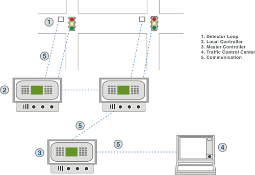
- Detection. Detectors are used to gather information about the “conditions” used in the local traffic signal controller at each intersection and to allocate time at the intersection. Detection may also be used to collect data that can support monitoring, managing, and measuring performance. Few agencies achieve all three functions with their detection system.
- Local Controller. (further described in Chapter 5 and 6) The local controller operates the displays through the load switches using the signal timing provided by the user. The local controller implements specific strategies from field inputs or directly from the central signal system operator.
- Master Controller. The master controller is an optional component of a system that facilitates communication between the “central” signal system and the local controllers for control decisions. The primary functions of the on-street master controller are to select the timing plans for a group of intersections, to process and store detector count information, and to monitor equipment operation.
- Traffic Control Center (Signal System). The traffic control center is used for a variety of functions. The central signal system is an alternative to using a master controller and contains the operational database that stores controller data, monitors the system, and allows timing and other parameters to be modified. It may also facilitate the implementation of the advanced concepts described in Chapter 9.
- Communication. Several components of the system communicate through many forms. Communication facilitates coordination between controllers (see below).
These system components works together to implement a control strategy, such as coordination. To understand the implementation of the strategy, one must have a rudimentary understanding of how a system is configured and how coordination is maintained at a system level. This is particularly important for troubleshooting.
4.2 PHASING OVERVIEW
Phasing represents the fundamental method by which a traffic signal accommodates the various users at an intersection in a safe and efficient manner. This section first presents definitions and terminology and then discusses the variety of phasing techniques used in common practice.
4.2.1 Definitions and Terminology
Definitions used in traffic signal timing have resulted in some confusion. In many cases, “the old way of doing things” confounds the ability of the industry to educate people new to the field. Over the years, the description of the “individual movements” of the dual-ring 8-movement controller as “phases” has blurred into common communicated terminology of “movement number” being synonymous as “phase number”. Most signal designs and all controllers sold today provide eight standard phases within the signal controller; however, a four-phase intersection is commonly referred to in the literature to represent a standard four-legged intersection with protected left turns on all approaches. It is the intent of this document to reduce the ambiguous use of the term “phase” and for the purposes of this document, a phase is defined as a controller timing unit associated with the control of one or more movements. Each phase at an intersection has a set of timing, possibly containing vehicle and pedestrian timing. A phase may control both a through movement and a right turn movement on an approach.
The MUTCD defines a signal phase as the right-of-way, yellow change, and red clearance intervals in a cycle that are assigned to an independent traffic movement or combination of traffic movements.
Two additional terms that are important for improving the use of terminology within the signal timing industry is to articulate is the use of movement and interval. A movement reflects the user perspective and is defined by the user type and the action that is taken (turning movement for a vehicle or pedestrian crossing). Two different types of movements include those that have the right of way and those that must yield consistent with the rules of the road or the Uniform Vehicle Code.
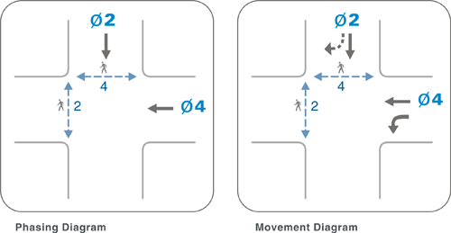
A simple example of the concept of movements is the intersection of one-way streets shown in Figure 4-1. In this example, the intersection is operated by two phases (2 and 4) and pedestrians are accommodated as concurrent movements to the traffic. Phase 2 will include a through and a right turn movement, while phase 4 will have a through and a left turn movement (appropriate turning movements are omitted from the diagram for simplicity). The right turn on phase 2 must yield to pedestrian traffic crossing the west leg of the intersection.
Figure 4-2 Phasing and movement diagram for the intersection of two one-way streets
An interval is a duration of time during which the signal indications do not change. For example, a pedestrian phase contains three intervals—Walk, Flashing Don’t Walk, and solid Don’t Walk—and within the Walk and Flashing Don’t Walk intervals, the corresponding through movement will remain green.
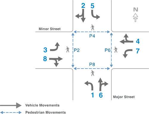
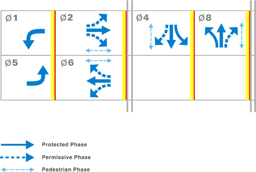
The movements served at an intersection can be categorized by the various users: vehicles, pedestrians, bicyclists, and transit. Figure 4-2 illustrates the typical vehicle and pedestrian movements at a four-leg intersection. In the context of this figure, bicycle and transit movements track the same paths as vehicle movements. These movements are regulated by the signal controller through their allocation to one or more signal phases. The following list defines some of the terms used to describe vehicle and pedestrian phasing (4):
- A vehicular phase is defined as a phase that is allocated to one or more vehicular traffic movements, as timed by the controller unit.
- A pedestrian phase is defined as a traffic phase allocated to pedestrian traffic that may provide a pedestrian indication either concurrent with one or more vehicular phases, or separate from all vehicular phases.
- A traffic phase is defined as the green, change, and clearance intervals in a cycle assigned to specified movement(s) of traffic.
- A cycle is defined as the total time to complete one sequence of signalization for all movements at an intersection. In an actuated controller unit, the cycle is a complete sequence of all signal indications.
The assignments shown are typical for eight-phase controller operation although other assignments are possible. As can be seen in Figure 4-3, left-turn movements are assigned odd number phases, while through movements are assigned to even number phases. In this example, the southbound left-turn movement is protected and is associated with phase 5. The right-turn movements are not typically assigned to separate phases. For example, the westbound right-turn movement is compatible with the westbound through movement and thus shares phase 4.
Typically, a pedestrian movement is associated with the concurrent vehicular phase running parallel and adjacent to it. As indicated earlier, this phase may include the concurrent right-turn movement that is associated with the through movement. As illustrated in Figure 4-3, pedestrians crossing the northern leg of the intersection are assigned the concurrent westbound vehicular phase (phase 4), which conflicts with the eastbound left turn (phase 3), this is further described in the next section. The operation of a concurrent phase is influenced by both the vehicular and pedestrian movements that it serves.
Figure 4-3 Typical vehicular and pedestrian movements at a four-leg intersection
4.2.2 Ring-and-Barrier Diagrams
Modern U.S. practice for signal control organizes phases by grouping them in a continuous loop (or ring) and separating the crossing or conflicting traffic streams with time between when they are allowed to operate, either by making the movements sequential or adding a barrier between the movements. The ring identifies phases that may operate one after another and are typically conflicting phases organized in a particular order. For instance, it may be desirable to separate the traffic traveling through the intersection in the northbound direction from the southbound left turn movement. A change interval and clearance time is used to separate that movement in time.
In Figure 4-4, a “barrier” would be used to separate the east-west movements from north-south movements to avoid operating conflicting movements at the same time. They are also used to define a relationship between the rings to assure compatible movements. The barrier represents a reference point in the cycle at which a phase in each ring has reached a point of termination; both rings must cross the barrier simultaneously.
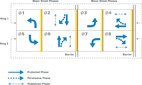
The time sequence of phases can be described using a ring and barrier diagram. Some common rules for number phases at an intersection (which are applicable to the diagram) are provided in the following list, which assumes leading left turns and separate left-turn phases.
- Phases 1, 2, 3, and 4 are assigned to Ring 1. Phases 5, 6, 7, and 8 are assigned to Ring 2.
- Phases 1, 2, 5, and 6 are assigned to Barrier 1. Phases 3,4,7, and 8 are assigned to Barrier 2.
- A phase pair contains two phases within the same ring and barrier that cannot be displayed concurrently. Examples of phase pairs include 1+2, 5+6, 3+4, and 7+8. Phases within a phase pair can be reversed (e.g. 2+1, 6+5, etc.) Phase pairs within the same barrier must end simultaneously (i.e., end at the barrier). For example, phase pairs 1+2 and 5+6 must end simultaneously at the end of barrier 1 and phase pairs 3+4 and 7+8 must end simultaneously at the end of barrier 2.
- Phase pair 1+2 can operate concurrently with phase pair 5+6. Phase pair 3+4 can operate concurrently with phase pair 7+8. These phase pairs are also known as concurrency groups because they can time together.
- One common practice is to assign phases 2 and 6 to the major street movements and the phases on the other side of the barrier to the minor road movements. Another practice is to define this by direction (phase 4 may be the most northerly pointed phase).
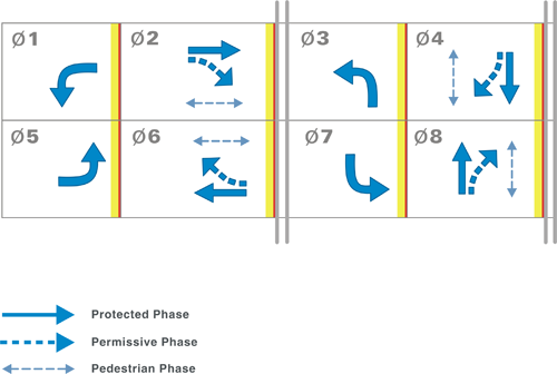
An example ring diagram is shown in Figure 4-4. The sequence of phases is shown as they occur in time, proceeding from left to right. The figure illustrates a phase sequence with left-turn movements leading the opposing through movements on both the major and minor streets. The diagram shows phase 1 and 5 ending at the same time, but they operate independently and can end at different times. The subsequent phase (phases 2 and 6 respectively) may begin once the previous phase has used its time. Once the barrier is crossed phases 3 and 7 operate followed by phases 4 and 8. The cycle ends with the completion of phases 4 and 8.
Figure 4-4 Standard ring-and-barrier diagram
When considering signal phasing it is helpful to start at the most basic, one where two one-way streets intersect. Figure 4-5 shows a ring and barrier structure that compliments the phase diagram described previously in Figure 4-3. All movements on the street are served (vehicles, bicycles, and pedestrians) in one direction during one phase, and all movements on the cross street during the other phase. It should be noted that it is common practice to assign pedestrians to a through traffic movement, with the underlying assumption that a motorist or bicyclist making a right turn must yield to pedestrians as per most Uniform Vehicle Code (5). However, care should be exercised with this concurrent pedestrian phasing approach when there are exclusive right-turn lanes with high right turn volumes (6].
Figure 4-5 Ring-and-barrier diagram for intersection of two one-way streets
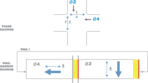
In this example, the left-turning movements are either non-existent or prohibited (phase 2) or are protected (phase 4). Application of this concept at a more typical intersection of two-way streets uses the standard ring and barrier structure described in Figure 4-4.
Assignment of phase numbers to signalized intersections is somewhat arbitrary based on historical design principles, but there are some rules that have been applied to standardize operation.
Depending on the complexity of the intersection, 2 to 8 phases are typically used, although some controllers can provide up to 40 phases to serve complex intersections or sets of intersections. Developing an appropriate phasing plan begins with determining the left-turn phasing type at the intersection. Section 4.4 presents some of the guidance related to selection of appropriate left turn phasing based on traffic volumes and safety experience.
4.3 LEFT-TURN DISPLAY OPTIONS
There are five options for the left-turn phasing at an intersection: permissive only, protected only, protected-permissive, split phasing, and prohibited. Phasing can have a significant impact on signal system effectiveness for a number of reasons, including:
- Permissive only left turn operation may reduce delay for the intersection, but may adversely affect intersection safely, because it requires motorists to choose acceptable gaps.
- Protected only left-turn phases may reduce delay for turning vehicles but are likely to increase overall intersection delay.
- Protected-permissive left turn phases can offer a good compromise between safety and efficiency but could limit available options to maximize signal progression during coordination unless innovative displays are used.
- Split phasing may be applicable with shared lanes, but could increase coordinated cycle length if both split phases are provided a concurrent pedestrian phase.
- Prohibited left turns may be used selectively to reduce conflicts at the intersection.
4.3.1 Permissive Only Left-Turn Phasing
Permissive only operation requires left-turning drivers to yield to the conflicting vehicle and pedestrian traffic streams before completing the turn. In the permissive mode, the left-turn movement is served concurrently with the adjacent through movement. Both the left turn and the opposing through movements are presented with a circular green indication. Thus, in this left turn display option, a green arrow is never provided.
Permissive operation is primarily used when traffic is light to moderate and sight distance is adequate. This display option provides the most efficient operation for green allocation at the intersection. The efficiency of this mode is dependent on the availability of gaps in the conflicting streams through which the turn can be safely completed. This mode can have an adverse affect on safety in some situations, such as when the left-turn driver's view of conflicting traffic is restricted or when adequate gaps in traffic are not present. The yellow trap can occur for the “permissive only” left turn when the opposite direction has a lagging left turn movement. Figure 4-6 and the following figures are adapted from those presented in the Signalized Intersections: Informational Guide Report and thus, phase 2 is defined as the eastbound movement.
Figure 4-6 Ring-and-barrier diagram showing permissive phasing
4.3.2 Protected Only Left-Turn Phasing
Protected only operation assigns the right-of-way to drivers turning left at the intersection and allows turns to be made only on a green arrow display. This operation provides for efficient left-turn movement service; however, the added left-turn phase increases the lost time within the cycle length and may increase delay to the other movements. An exclusive left-turn lane is typically provided with this phasing as shown in Figure 4-7. The left-turn phase is indicated by a green arrow signal indication. This type operation is recognized to provide the safest left-turn operation.
\Figure 4-7 Ring-and-barrier diagram showing protected phasing
4.3.3 Protected-Permissive Left-Turn Phasing
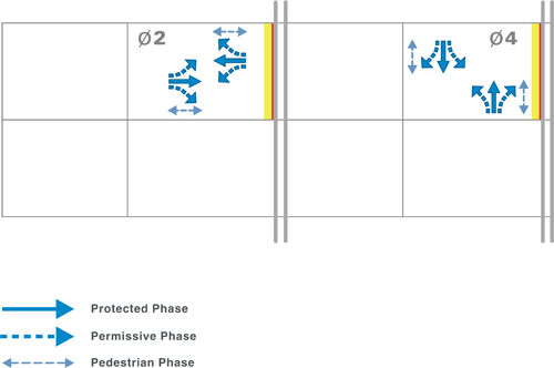
Protected-permissive operation represents a combination of the permissive and protected modes. Left-turning drivers have the right-of-way during the protected left-turn phase. They can also complete the turn "permissively" when the adjacent through movement receives its circular green indication as illustrated in Figure 4-8. This mode provides for efficient left-turn movement service, often without causing a significant increase in delay to other movements. This mode also tends to provide a relatively safe left-turn operation, provided that adequate sight distance is available and turns during the permissive component can be safely completed.
Figure 4-8 Ring-and-barrier diagram showing protected-permissive phasing
Protected-permissive phasing should be used with caution when a phasing sequence other than lead-lead left-turn phasing is being deployed. Section 4.4.2 provides additional detail on this matter.
4.3.4 Split Phasing
Split phasing represents an assignment of the right-of-way to all movements of a particular approach, followed by all of the movements of the opposing approach. This is depicted in Figure 4-9. Spilt phasing may be necessary when intersection geometry results in partially conflicting vehicle paths through the intersections or where the approaches are offset such that left turning vehicles would have to occupy the same space to complete their turns. Split phasing avoids the conflict of 10 opposing left turn vehicle paths. Similarly, if the intersection has high left turn and through volume, the traffic engineer may have to use shared left turn and through lanes to make efficient use of the approach which would also result in split phasing for the approach.
Figure 4-9 Ring-and-barrier diagram showing split phasing
Split phasing may be helpful if any of the following conditions are present (7):
- There is a need to accommodate one or more left-turn lanes on each approach, but sufficient width is not available to ensure adequate separation in the middle of the intersection. This problem may also be caused by a large intersection skew angle.
- The larger left-turn lane volume is equal to its opposing through lane volume during most hours of the day ("lane volume" represents the movement volume divided by the number of lanes serving it.)
- The width of the road is constrained such that an approach lane is shared by the through and left-turn movements yet the left-turn volume is sufficient to justify a left-turn phase.
- One of the two approaches has heavy volume, the other approach has minimal volume, and actuated control is used. In this situation, the phase associated with the low-volume approach would rarely be called and the intersection would function more nearly as a "T" intersection.
- Crash history indicates an unusually large number of sideswipe or head-on crashes in the middle of the intersection and involving left-turning vehicles.
This phasing is typically less efficient than other types of left-turn phasing. It typically increases the cycle length, or if the cycle length is fixed, reduces the time available to the intersecting road.
4.3.5 Prohibition of Left-Turns as a Phasing Option
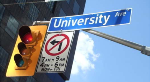
Prohibition of left turns on an approach is an option that has been implemented in some cases to maintain mobility at an intersection. In this case, a supplemental sign may be provided that indicates “no left turn”. In some cases, these have been applied only during certain times of day, when gaps in traffic are unavailable and operation of permitted phasing may be unsafe. Figure 4-10 is an example from Toronto, Ontario, that prohibits left turns during the morning and evening periods.
Figure 4-10 Prohibited left turns by time of day
In general, the operational mode used for one left-turn movement on a road is also typically used for the other (opposing) left-turn movement. For example, if one left-turn movement is permissive, the opposing left turn is also permissive. However, this agreement is not required and the decision of mode should be movement-specific based on factors such as sight distance, volumes, number of turning lanes, number of opposing lanes, and leading vs lagging left turn operation.
4.3.6 Guidelines for Selecting Left-Turn Phasing
A variety of guidelines exist that have been developed to indicate conditions where the benefits of a left-turn phase typically outweigh its adverse impact to intersection operation. Many of these guidelines indicate that a left-turn phase can be justified based on consideration of several factors that ultimately tie back to the operational or safety benefits derived. These factors include:
- Left-turn and opposing through volumes
- Number of opposing through lanes
- Cycle length
- Speed of opposing traffic
- Sight distance
- Crash history
The flowchart shown in Figure 4-11 can be used to assist in the determination of whether a left-turn phase is needed and whether the operational mode should be protected or protected-permissive.
These guidelines were derived from a variety of sources (8;9). Application of the flowchart requires the separate evaluation of each left-turn movement on the subject road.
Figure 4-11 Guidelines for determining the potential need for a left-turn phase
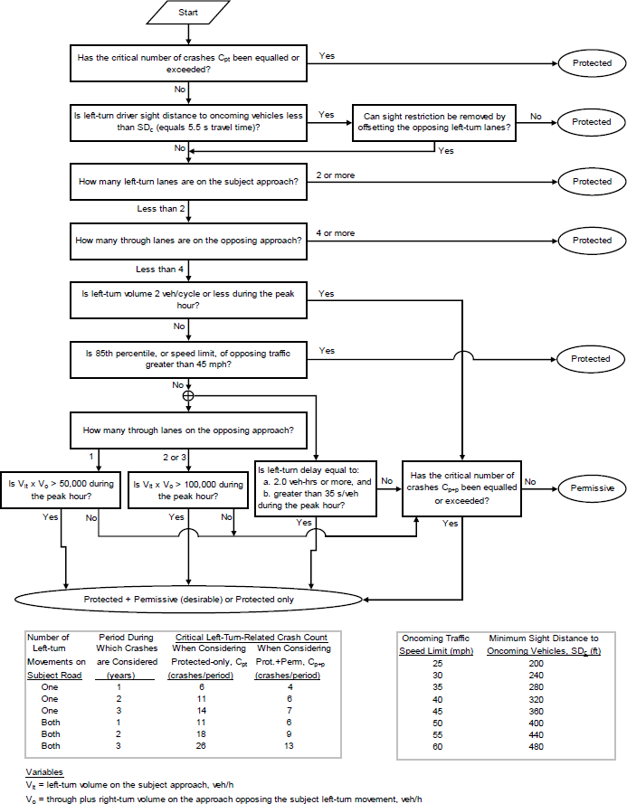
Source: Adapted from (Kell and Fullerton, 1998; Orcutt, 1993; Traffic Engineering Manual, 1999).
The objective of the flow chart is to identify the least restrictive left-turn operational mode. A secondary objective is to provide a structured procedure for the evaluation of left-turn phasing for the purpose of promoting consistency in left-turn phase application.
The critical left-turn crash counts identified in the figure are based on an underlying average critical crash frequency and recognize the inherent variability of crash data. The underlying averages are 1.3 crashes per year and 3.0 crashes per year when considering protected-permissive and protected only left-turn phasing, respectively. If the reported crash count for existing permissive operation exceeds the critical value, then it is likely that the subject intersection has an average left-turn crash frequency that exceeds the aforementioned average (5 percent chance of error) and a more restrictive operational mode would likely improve the safety of the left-turn maneuver.
The flowchart has two alternative paths following the check of opposing traffic speed. One path requires knowledge of left-turn delay; the other requires knowledge of the left-turn and opposing through volumes. The left-turn delay referred to in the flowchart is the delay incurred when no left-turn phase is provided (i.e., the left-turn movement operates in the permissive mode).
4.4 LEFT-TURN PHASE SEQUENCE OPTIONS
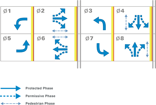
It may be advantageous under certain circumstances to change the sequence in which left turns are served relative to their complementary through movements. This is done by reversing the sequence of a pair of complementary phases, as is shown for phases 1 and 2 in Figure 4-4. In this example, phase 1 is said to “lag” phase 2. Specifically, Figure 4-12 shows phases 2 and 6 starting and ending at different times in the cycle. This independence between the through phases can be desirable under coordinated operations because it can accommodate platoons of traffic arriving from each direction at different times.
Figure 4-12 Ring-and-barrier diagram showing protected lead-lag left turns
4.4.1 Lead-Lead Left-Turn Phase Sequence
The most commonly used left-turn phase sequence is the "lead-lead" sequence which has both opposing left-turn phases starting at the same time. If a single ring structure is used, then the two phases also end at the same time. If an actuated dual ring structure is used, then each left-turn phase 14 is assigned to a different ring such that each can end when the left-turn demand is served (i.e., they can end at different times). The advantages of this phasing option are: (1) that drivers react quickly to the leading green arrow indication and (2) it minimizes conflicts between left-turn and through movements on the same approach, especially when the left-turn volume exceeds its available storage length (or no left-turn lane is provided). A more detailed discussion of the advantages of leading left-turn phases is provided in Chapter 13 of the Traffic Engineering Handbook (10).
4.4.2 Lag-Lag Left-Turn Phase Sequence
This left-turn phase sequence is most commonly used in coordinated systems with closely spaced signals, such as diamond interchanges. It has both opposing left-turn phases ending at the same time. If it is implemented in a single ring structure, then the two phases also start at the same time. If a dual-ring structure is used, then each left-turn phase is assigned to a different ring such that each can start when the left-turn demand is served (i.e., they can start at different times).
Lagging left-turn phasing is also recognized to offer operational benefits for the following special situations:
- At "T" intersections when the one left-turn phase that exists is combined with a protected-permissive mode.
- At the intersection of a two-way street and a one-way street where the one left-turn phase that exists is combined with a protected-permissive mode.
- At a n interchange, or a pair of closely-spaced interconnected intersections, where both intersections have a left-turn phase and each are combined with the protected-permissive mode.
When used with protected phasing, this phase sequence provides a similar operational efficiency as a lead-lead or lead-lag phase sequences. However, differences emerge when they are used with protected-permissive mode. One disadvantage of lagging left-turn phases is that drivers tend not to react as quickly to the green arrow indication. Another disadvantage is that, if a left-turn bay does not exist or is relatively short, then queued left-turn vehicles may block the inside through lane during the initial through movement phase.
When lag-lag phasing is used at a four-leg intersection where both phases are used with the protected-permissive mode, then both left-turn phases must start at the same time to avoid the "yellow trap" (or left-turn trap) problem, illustrated in Figure 4-13. This problem stems from the potential conflict between left-turning vehicles and oncoming vehicles at the end of the adjacent through phase. Of the two through movement phases serving the subject street, the trap is associated with the first through movement phase to terminate and occurs during this phase's change period. The left-turn driver seeking a gap in oncoming traffic during the through phase, first sees the yellow ball indication; then incorrectly assumes that the oncoming traffic also sees a yellow indication; and then turns across the oncoming traffic stream without regard to the availability of a safe gap.
The "yellow trap" problem can be alleviated by using one of the following techniques:
- Use the protected-only mode for both left-turn movements.
- Use a single-ring structure to ensure that both through movement phases end at the same time (use with the protected-permissive mode).
- Use a flashing yellow arrow or"Dallas Display" for both left-turn signal heads and use the protected-permissive mode for both left-turn movements.
Figure 4-13 Illustration of the yellow trap
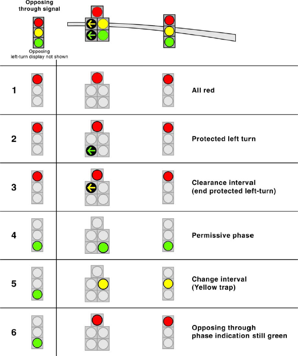
Source: FHWA Signalized Intersection Guide
In fact, under at least one condition, the second technique can operate more efficiently than dual-ring lead-lead phasing. This condition occurs when the left-turn volume is moderate to heavy and relatively equal on both approaches. Regardless, a detailed operational evaluation should always be used to confirm that lag-lag phasing operates more efficiently than other phasing options.
The third technique avoids the yellow trap by using an overlap in the controller and a five-section left-turn signal head. An overlap is a controller output (to the signal head load switch) that is associated with two or more phases. In this application, the left-turn green and yellow arrow indications are associated with the subject left-turn phase; and the left-turn green, yellow, and red ball indications are associated with the opposing through movement phase (as opposed to those of the adjacent through phase). Two types of protected-permissive displays have been developed to provide more operational flexibility and avoid the “yellow trap” problem: the flashing yellow arrow and the “Dallas Display”.
The flashing yellow arrow is contained within a three-, four-, or five-section head and provides a permissive indication to the driver that operates concurrent with the opposing through movement rather than the adjacent through movement. Researchers for National Cooperative Highway Research Program (NCHRP) Project 3-54 studied alternatives to the green ball indication for permissive left turn movements. This study was conducted over a 7-year period and comprised a very comprehensive research process, including engineering analyses, static and video-based driver comprehension studies, field implementation, video conflict studies, and crash analyses. This study (11) recommended that a flashing yellow arrow be allowed as an alternative to the circular green for permissive left-turn intervals.
- The flashing yellow arrow was found to be the best overall alternative to the circular green as the permissive signal display for a left-turn movement.
- A flashing yellow arrow was found to have a high level of understanding and correct response by left-turn drivers, and a lower fail-critical rate than the circular green.
- The flashing yellow arrow display in a separate signal face for the left-turn movement offers more versatility in field application. It is capable of being operated in any of the various modes of left-turn operation by time of day, and is easily programmed to avoid the "yellow trap" associated with some permissive turns at the end of the circular green display.
Subsequent to the publication of the NCHRP research, FHWA has issued an Interim Approval and no longer requires a Request to Experiment for this display. As of this writing, it has been proposed for inclusion in the next revision to the MUTCD.
In the “Dallas Display”, the signal head uses louvers on the yellow and green ball indications to restrict visibility of the left-turn display to adjacent lanes. The louvered signal head is referred to as the "Dallas Display." With this display, both left-turn phases can operate in the protected-permissive mode and the trap is avoided.
4.4.3 Lead-Lag Left-Turn Phase Sequence
This left-turn phase sequence is generally used to accommodate through movement progression in a coordinated signal system. The aforementioned "yellow trap" may occur if the leading left-turn movement operates in the protected-permissive mode and the two through movement phases time concurrently during a portion of the cycle. The "yellow trap" problem can be alleviated by using one of the following techniques:
- Use the protected only mode for the leading left-turn movement.
- Use a single ring structure that ensures that the two through movement phases do not time concurrently (use with the protected-permissive mode).
- Use a flashing yellow arrow or "Dallas Display" for the left-turn signal head associated with the leading left-turn phase and use the protected-permissive mode for both left-turn movements.
The first two techniques will likely have an adverse effect on operations, relative to a dual ring implementation of lead-lag phasing with protected-permissive operation. However, they avoid the potential adverse effect a yellow trap would have on safety.
The third technique avoids the yellow trap by using an overlap in the controller and a five section left-turn signal head. This use of overlap was described in the previous discussion of lag-lag left-turn 17phasing. However, in practice, the Dallas Display is used for both the leading and the lagging left-turn signal heads because it improves operational performance (12).
Lead-lag phasing is also recognized to offer operational benefits for the following special situations:
- Where there is inadequate space in the intersection to safely accommodate the simultaneous service of the opposing left-turn movements. However, in this application, a single ring structure (or equivalent functionality in a dual ring structure) should be used to ensure that the two left-turn phases never time concurrently.
- Intersections where the leading left-turn movement is not provided an exclusive lane (or the available left-turn storage is relatively small).
4.5 PEDESTRIAN PHASING
Pedestrian movements are typically served concurrently with the adjacent through movement phase at an intersection. This is done to simplify the operation of the intersection primarily and is largely a legacy issue in our application of signal logic and control. Typical application of pedestrian operation puts pedestrians in conflict with right-turning vehicles and left-turning vehicles that operate in a permissive mode, by inviting their movement at the same time. There are specific measures that can be used to mitigate this potential conflict, three common options include:
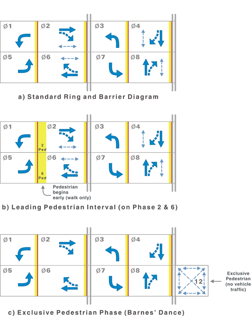
- Leading pedestrian interval. As shown in Figure 4-14b, a leading pedestrian interval starts a few seconds before the adjacent through movement phase. This allows pedestrians to establish a presence in the crosswalk and thereby reduce conflicts with turning vehicles. This option supports improved safety for pedestrians by allowing them increased visibility within the intersection and is applicable to intersections where there are significant pedestrian-vehicle conflicts (13).
- Lagging pedestrian interval. A lagging pedestrian interval option operates similarly to a leading pedestrian interval, except that the pedestrian walk interval starts several seconds after the adjacent through movement phase. This option allows a waiting right-turn queue to clear before the pedestrian walk indication is presented and reduces conflicts with right-turning vehicles. It is applicable to intersections where there is: (1) a high right-turn volume and (2) either an exclusive right-turn lane (or lanes) or the two intersecting roads have one-way traffic (14).
- Exclusive pedestrian phase (also “pedestrian scramble” or “Barnes’ Dance”) As shown in Figure 4-14c, an exclusive pedestrian phase dedicates an additional phase for the exclusive use of all pedestrians. This additional phase is configured such that no vehicular movements are served concurrently with pedestrian traffic. During this phase, pedestrians can cross any of the intersection legs and may even be allowed to cross the intersection in a diagonal path. This type of phasing has an advantage of reducing conflicts between right-turning vehicles and pedestrians, but it comes at a penalty of reduced vehicular capacity and longer cycle lengths (which increases delay to all users). The exclusive pedestrian phase is not frequently used but can be found in the central business districts of several cities, including Denver and San Francisco.
Figure 4-14 Ring-barrier diagrams showing a leading pedestrian interval and an exclusive pedestrian phase
4.6 RIGHT-TURN PHASING
Two types of right-turn phasing are addressed in this section. The first type is based on the addition of a phase to the signal cycle that exclusively serves one or more right-turn movements. This type of right-turn phasing is rarely used. If it is being considered, then its operational or safety benefits should be evaluated and shown to outweigh its adverse impact on the efficiency of the other intersection movements.
The second type of right-turn phasing is based on the assignment of the right-turn movement to the phase serving the complementary left-turn movement on the crossroad. The following conditions should be satisfied before using this type of right-turn phasing:
- The subject right-turn movement is served by one or more exclusive right-turn lanes.
- The right-turn volume is high (300 vehicles per hour or more) and is a critical movement at the intersection (see Chapter 3 for more details).
- A protected left-turn phase is provided for the complementary left-turn movement on the intersecting road.
- U-turns from the complementary left-turn are prohibited.
If the aforementioned conditions are satisfied, then the appropriate operational mode can be determined. If the through movement phase for the subject intersection approach serves a pedestrian movement, then the right-turn phasing should operate in the protected-permissive mode. As shown in Figure 4-15, the permissive right-turn operation would occur during the adjacent through movement phase, and the protected right-turn operation would occur during the complementary left-turn phase.
Figure 4-15 Phase diagram illustrating a right-turn overlap
If the through movement phase for the subject intersection approach does not serve a pedestrian movement, then the right-turn phasing should operate in the protected only mode during both the adjacent through movement phase and the complementary left-turn phase. A controller overlap may be used to provide this sequence.
4.7 DETECTION FUNDAMENTALS
Detection at an intersection informs the signal controller that a user desires service (often called “demand” for service). Detectors place calls into the traffic signal controller. The controller uses this information and the signal timing to determine the display provided to the users. Detection for pedestrians is limited in most cases to push buttons as shown in Figure 4-16, although accessible 20 pedestrian signal detectors are increasing in their use. The FHWA’s Pedestrian Facilities User Guide-Providing Safety and Mobility (15) is a resource describing more detail related to other equipment.
Figure 4-16 Examples of pedestrian push buttons
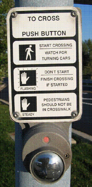
Source: Fred Ranck,FHWA, Illinois, Naperville, intersection of Washington Street at Shuman Blvd
There are various forms of vehicle detection technologies, and strengths and weaknesses of each are described in the Traffic Detector Handbook, 3rd edition (2006). The detection design for an intersection describes the size, number, location, and functionality of each detector. Most engineering drawings include the wiring diagram for how detectors are associated to phases. Signal timing settings such as the passage time, delay, extend, and other related parameters are described in more detail in Chapter 5.
The size and location of detectors is an important element in traffic signal design. Detectors can consist of one 6-foot-by-6-foot inductive loop detector, a series of closely spaced 6-foot-by-6-foot loop detectors (may be circular in shape as shown in Figure 4-17), one long (6-foot-by-40-foot) loop detector, or alternative detection technology (e.g., video, microwave, etc.) that can monitor an 21 equivalent length of roadway. This detection zone can be used to meet the objectives described below.
Figure 4-17 Example of vehicle detector design (through lane on side street)
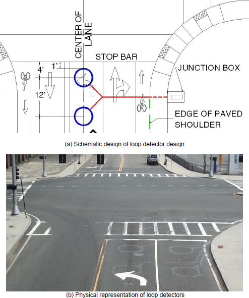
(a) Schematic design of loop detector design
(b) Physical representation of loop detectors
A “call” represents the controller’s registration of a request for service on a specified phase. A call can be triggered by an actuation from any detection, vehicular, pedestrian, or other or through a controller function. When triggered by a vehicle detection unit, the call’s start and end time can be equal to that of the actuation from the detection unit, or it can be modified using the controller’s detector parameters (e.g., delay, extend, call, queue, etc.). These parameters are described in Chapter 5.
4.7.1 Detection Design Objectives
The objective of detection is to detect vehicle presence and identify gaps in vehicle presence that are sufficiently long to warrant terminating the phase. There are many objectives of detection design that can be characterized with the following statements:
- Identify vehicle presence on a phase.
- Extend the phase to serve queued traffic and that which is progressed from upstream traffic signals.
- Identify gaps in traffic where the phase may be ended and extend the green.
- Provide a safe phase termination for high-speed movements by minimizing the chance of a driver being in the indecision zone at the onset of the yellow indication.
The first and fourth objectives are safety related. The first objective addresses expectancy, while the fourth specifically addresses the potential crashes as a result of phase termination. The fourth objective is achieved by using advance detectors on the approach. The location of these detectors can vary and depends on the detection technology used as well as intersection approach speed. The safety benefit of this design tends to be more significant on high-speed approaches. The other objectives focus on intersection efficiency.
The second and third objectives are designed to address efficiency. During low volume (late night or off-peak) conditions, detection should seek to serve all traffic identified without stopping. In peak conditions, green allocation should seek to measure flows and maintain flows that are near saturation flow as described in Chapter 3. Detection timing to achieve this objective will be discussed in more detail in Chapter 5.
4.7.2 Detector Operating Modes
The detection operating mode refers to the way the detection unit measures activity and is set in the detection unit. It also affects the duration of the actuation submitted to the controller by the detection unit. One of two modes can be used: presence or pulse. The presence mode is typically the default mode.
Pulse Mode
Pulse mode is used to describe a detector which detects the passage of a vehicle by motion only (point detection). This is characterized by a short “on” pulse sent to the controller of 0.10 to 0.15 seconds duration. The actuation starts with the arrival of the vehicle to the detection zone and ends after the pulse duration. This mode is typically used when the detectors are located upstream of the stop line and the associated detector channel operates in the locking mode.
Presence Mode
Presence mode is used to measure occupancy and the actuation starts with the arrival of the vehicle to the detection zone and ends when the vehicle leaves the detection zone. Thus, the time duration of the actuation depends on the vehicle length, detection zone length, and vehicle speed.
Presence mode measures the time that a vehicle is within the detection zone and will require shorter extension (or gap) timing with its use.
Presence mode is typically used with long-loop detection located at the stop line. In this application, the associated detector channel in the controller is set to operate in the non-locking mode (see next section). In this mode, the delay or extend parameters in the controller (described in detail in Chapter 5) can be used to modify the call start and end times. Alternatively, the delay or extend functions in the detection unit could also be used to adjust the start and end time of the actuation. The combination of presence mode operation and long-loop detection typically require a small passage time value to maintain efficiency. This characteristic tends to result in an operational benefit through efficient queue service.
Modifiers to the detector settings are commonly handled in the controller. This has increased in popularity because it provides a single location for information on all phases at the intersection.
4.7.3 Controller Memory Modes
Controller memory modes refer to the controller’s ability to “remember” (i.e., retain) a detector actuation. One of two modes can be used: non-locking or locking. This mode is set in the controller for each of its detector channel inputs. It dictates whether an actuation received during the red interval (and optionally, the yellow interval) is retained until the assigned phase is served by the controller. All actuations received during the green interval are treated as non-locking by the controller. The non-locking mode is typically the default mode.
Non-locking Mode
In the non-locking mode, an actuation received from a detector is not retained by the controller after the actuation is dropped by the detection unit. The controller recognizes the actuation only during the time that it is held present by the detection unit. In this manner, the actuation indicates to the controller that a vehicle is present in the detection zone and the controller converts this actuation into a call for service. This mode is typically used for phases that are served by stop line detection. It allows permissive movements (such as right-turn-on-red) to be completed without invoking a phase change. In doing so, it improves efficiency by minimizing the cycle time needed to serve minor movement phases. Non-locking mode is not typically used with pulse detection due to an inability to detect vehicle presence after the pulse duration elapses.
Locking Mode
In the locking mode, the first actuation received by the controller on a specified channel during the red interval is used by the controller to trigger a continuous call for service. This call is retained until the assigned phase is serviced, regardless of whether any vehicles are waiting to be served. This mode is typically used for the major-road through movement phases associated with a low percentage of turning vehicles (as may be found in rural areas). One advantage of using this mode is that it can eliminate the need for stop line detection, provided that advance detection is provided and that it is designed to ensure efficient queue service.
4.7.4 Detection Design for High-Speed Approaches
Detection designs for high speed approaches (speeds greater than 35 mph) have the objective to not only service the queue at the beginning of green but also to safely terminate the phase in the presence of a conflicting call. Stop bar detection is usually used to clear the queues and the multiple upstream detectors are used to safely terminate the phase. For efficient operation, the stop bar detector should be programmed as a queue detector so that the stop bar detector is disconnected after the queue clears and only the upstream detectors are used to safely terminate the phase. When stop bar detectors are not used, volume density functions should be used to provide appropriate minimum green time to clear the queues.
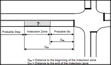
The design of advance detection on high-speed approaches requires special attention. Drivers within a few seconds travel time of the intersection tend to be indecisive about their ability to stop at the onset of the yellow indication. This behavior yields an "indecision zone" (also known as a “dilemma zone”) in advance of the stop line wherein some drivers may proceed and others may stop. The location of this zone is shown in Figure 4-18.
Figure 4-18 Indecision zone boundaries on a typical intersection approach
The indecision zone location has been defined in several ways.
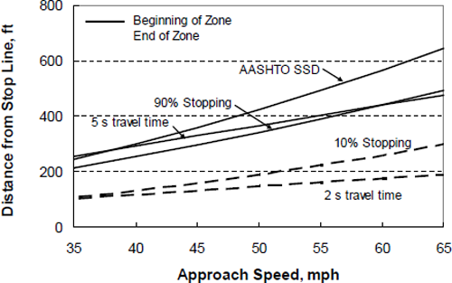
- Distance from stop line. Some researchers have defined it in terms of distance from the stop line (16;17). They define the beginning of the zone as the distance beyond which 90 percent of all drivers would stop if presented a yellow indication. They define the end of the zone as the distance within which only 10 percent of all drivers would stop. The distance to the beginning of the zone recommended by Zegeer and Deen corresponds to about 5 seconds of travel time. That recommended by ITE increases exponentially with speed, ranging from 4.2 to 5.2 s travel time, with the larger values corresponding to higher speeds.
- Travel time. Another definition of the indecision zone boundary is based on observed travel time to the stop line. Chang et al. (18) found that 85 percent of drivers stopped if they were more than 3 s from the stop line, regardless of their speed. Similarly, they found that drivers less than 2 s from the stop line would almost always continue through the intersection.
- Stopping sight distance. A third definition of the beginning of the indecision zone is based on safe stopping sight distance (SSD). A method for computing this distance is described in Chapter 3 of the AASHTO document, A Policy on the Geometric Design of Highways and Streets (19).
The zone boundaries obtained by these three definitions are compared in Figure 4-19. The boundaries based on distance typically have an exponential relationship. Those based on travel time have a linear relationship. Based on the trends shown in the figure, the beginning and end of the indecision zone tend to be about 5.5 and 2.5 seconds, respectively, travel time from the stop line. These times equate to about the 90th-percentile and 10th-percentile drivers, respectively.
Figure 4-19 Distance to the beginning and end of the indecision zone
For these types of designs, the furthest detector upstream of the stop bar is usually located at the beginning of the indecision zone of the approach design speed (85th-percentile approach speed). This is usually at a distance of 5 to 5.5 seconds of travel time. Subsequent detectors have a design speed of 10 mph lower than the upstream detector. Typically 3 to 4 detectors are used to enable safe termination of the high speed approach phase. The detectors are allowed to extend the phase by the passage time programmed in the controller or by the extension time on the detector itself (see Chapter 5).
Although the concept of the indecision zone has been known for many years, comprehensive research has not been completed to conclude what the appropriate way to address the human factors associated with intersection design and signal timing display. The indecision should not be confused with the dilemma faced by drivers determining whether there is distance to stop and, if not, to travel through the intersection before a conflicting movement receives a green indication.
4.7.5 Detection Design for Low-Speed Traffic Movements
Detection design for low speed traffic movements (speeds of 35 mph or less) has a different objective compared to the detection design for high speed traffic movements. The primary objective of detection on low speed approaches is to call a phase and clear the queue while minimizing delay. Due to lower speeds, there is less emphasis on protection from dilemma zone or indecision zone on the approach. Hence, some agencies use only stop bar detection for low speed approaches. Stop bar detectors are usually operating in the presence mode. This facilitates the primary objective of detector calling the phase and clearing the queues.
4.8 DETECTION APPLICATIONS
This section presents a series of detection applications.
4.8.1 Basic Fully-Actuated Design
This design is based on the following assumptions:
- A detection zone located at the stop line.
- The detectors are operating in the presence mode.
- Non-locking memory is used for the associated detector channel in the controller.
- No recall is used for the phase to which the detector is assigned.
The key element of this design is the determination of detection zone length. The optimal length represents a trade off in the desire to avoid both premature gap out and excessive extension of green. According to Lin (20), the ideal length of the stop line detection zone is about 80 feet. This length allows the passage time setting to be small such that the design is very efficient in detecting the end of queue while minimizing the chance of a premature gap-out. However, the installation and maintenance of such a long detector is often cost prohibitive and multiple detectors of a shorter length are often used. The following guidelines should be used to determine the appropriate length of the stop line detection zone:
- The detection zone should not be smaller than 20 feet.
- The zone should be positioned such that a queued vehicle cannot stop between its trailing edge and the crossroad.
- The zone should consist of one long detection zone or a series of loops. Other sensors that can provide the equivalent length of detection can also be used.
4.8.2 Volume-Density Design
This design is based on the following assumptions:
- One 6-foot detector is located upstream of the stop line.
- The detector unit is operating in the pulse mode.
- Locking memory is used for the associated detector channel in the controller.
- No recall is used for the phase to which the detector is assigned.
This design is not well-suited to approaches with a significant percentage of turning vehicles because these vehicles may unnecessarily submit a call for the through movement phase.
A key element of this design is the location of the detector. This location should be based on the desired maximum allowable headway for the design. Research has shown that maximum allowable headways in the range of 1.8 to 2.5 seconds yield the snappiest operation, values of 2.6 to 4.5 seconds will allow detected vehicles to use the green, but may result in extension of green during low flow periods (this is discussed further in Chapter 5). Lower values are more appropriate for higher volume conditions.
The advance detector should be located such that the travel time from the detector to the stop line for a vehicle traveling at the 85th percentile speed is equal to the maximum allowable headway. In this manner, the green interval is not unnecessarily extended by a vehicle that has crossed the stop line (as it is with stop line detection). Based on this principle, the recommended location for the detector is listed in Table 4-1 for a range of approach speeds.
With this design, the passage time setting is equal to the maximum allowable headway (which may vary if gap-reduction is used). Guidelines related to the detection design as it relates to signal timing are described in Chapter 5 for determining the appropriate minimum green interval. Gap-reduction is not essential with a maximum allowable headway of 3.0 s but should be considered for a maximum allowable headway of 4.0 s. If gap-reduction is used, then the minimum gap should be equal to 2.0 s. Guidelines for setting the time before reduction parameter and the time to reduce parameter are described in Chapter 5.
| 85th Percentile Approach Speed, mph | Distance between Detector and Stop Line, ft | |
|---|---|---|
| 3.0 s Max. Allowable Headway | 4.0 s Max. Allowable Headway1 | |
| 20 | 90 | 115 |
| 25 | 110 | 145 |
| 30 | 130 | 1752 |
| 35 | 155 | 2052 |
| 40 | 180 | 2352 |
| 45 | 200 | 2652 |
Notes:
|
||
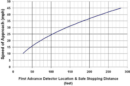
4.8.3 Multiple-Detector Design
This design technique, used by the city of Portland, Oregon, is based on the following assumptions:
- One 6-foot detector is placed at 60 feet (because safe stopping distance ends at 15 mph), this is the last detector the vehicle will cross.
- One 6-foot detector is located at the safe stopping distance upstream of the stop line, based on the approach speed; this is the first detector the vehicle will cross.
- At higher speeds, one or two additional detector(s) is(are) placed between the first advance detector and the last detector (at 60 feet).
- The detectors operate in presence mode.
- Non-locking memory is used for the associated detector channel in the controller.
- No recall is used for the phase to which the detector is assigned.
The first detector registers demand for the vehicles as they approach the stop bar. The second detector is used like a speed sieve to determine whether the vehicle can stop safely upon its approach to the intersection (based on the safe stopping distance from the second detector. This design is well-suited to approaches with a significant percentage of turning vehicles because it is likely these vehicles will gap out as the vehicle slows to make the turn at the intersection or upstream driveway. This is further illustrated in Figure 4-20.
Figure 4-20 Detector location for multiple detector technique (level approach)
Source: City of Portland, Oregon
A key element of this design is the use of detectors and extend values within the controller timing to reduce the time between successive vehicles. A sample table of extend values from the City of Portland is shown in Table 4-2.
| Approach Speed, mph | Location of Advance Detector (feet) | Location of Second Detector (feet) | Location of Detector Nearest Stop Bar (feet) | Extend (Carryover) Value from Upstream Detectors (secs)1 |
|---|---|---|---|---|
| 25 | 105 | 60 | - | 0.8 |
| 30 | 140 | 60 | - | 2.1 |
| 35 | 183 | 115 | 60 | 1.0 |
| 40 | 230 | 130 | 60 | 1.6 |
| 45 | 283 | 190 | 115 & 60 | 1.0 |
Notes:
|
||||
4.8.4 Left-Turn Movements
The guidelines provided in this section can be used to design the left-turn movement detection when this movement has an exclusive lane (or lanes). In general, the detection design for a left-turn movement should follow the guidelines offered for through movements, as described previously for basic fully-actuated design in Section 4.8.1. Some agencies use an additional detector approximately 100 feet upstream of the stop bar to provide some advance notice of a vehicle approaching the intersection. In this case, an extension (carryover) setting is provided to allow a vehicle leaving the first advance detector to reach the detection zone at the stop bar and a short gap setting is used for the phase (assuming stop bar detection in presence mode).
In cases where the left-turn movement operates in the protected-permissive mode and the conflicting through movement phase is on recall, then the stop line detection zone could be set back from the stop line one or two vehicle lengths. This technique assumes that one or two vehicles can be served at the end of the conflicting through phase. A call for the left-turn phase would only be registered if the left-turn queue extends back over the detection zone, in which case there would be more vehicles that could clear at the end of the through phase.
If the left-turn movement operates in the protected-permissive mode and the conflicting through movement phase is likely to rest in recall, then the controller’s delay parameter can be used with the channel assigned to the left-turn lane detector to minimize unnecessary phase changes. The delay value used should range from 3 to 15 seconds, with the larger values used when higher speeds and volumes exist on the conflicting approach. Most controllers have a detector switching setting that can be used to send calls from left-turn detectors to the adjacent through phases to extend the permissive green phase for both movements.
If the left-turn movement operates in the permissive or protected-permissive mode and the adjacent through movement phase is not on recall, then it may be desirable to extend the stop line detection zone beyond the stop line. This extension would be intended to minimize the potential for stranding a turning vehicle in the intersection at the end of the permissive period. It may also ensure that the left-turn movement is detected under low-volume conditions.
4.8.5 Right-Turn Movements
The guidelines provided in this section can be used to design the right-turn movement detection when this movement has an exclusive lane (or lanes). In general, the detection design for a right-turn movement should follow the guidelines offered for through movements, as described previously for basic fully-actuated design in Section 4.8.1.
If the right-turn volume is moderate-to-high and the volume on the intersecting road is relatively low (such that many gaps for right-turn-on-red exist), then the controller’s delay parameter can be used with the channel assigned to the right-turn lane detector to minimize unnecessary phase changes. The delay parameter should also be considered when a conflicting phase is on recall. The delay value used should range from 7 to 15 s, with the larger values used when higher speeds and volumes exist on the intersecting road.
If the right-turn volume is high but there are few gaps for right-turn-on-red, then the use of the delay parameter may not be appropriate because it may only increase the delay to the right-turning vehicles.
4.9 REFERENCES
- Rodegerdts, L.A., B. Nevers, B. Robinson, J. Ringert, P. Koonce, J. Bansen, T. Nguyen, J. McGill, D. Stewart, J. Suggett, T. Neuman, N. Antonucci, K. Hardy, and K. Courage. Signalized Intersections: Informational Guide. Report FHWA-HRT-04-091. Federal Highway Administration, Washington, D.C., 2004.
- Wu, C-S., C.E. Lee, R.B. Machemehl, and J. Williams. “Effects of Multiple-Point Detectors on Delay and Accidents.” Transportation Research Record 881. National Research Council, Washington, D.C., 1982, pp. 1-9.
- Manual on Uniform Traffic Control Devices. U.S. Department of Transportation, Washington, D.C., December 2003.
- National Transportation Communications for ITS Protocol: Object Definitions for Actuated Traffic Signal Controller (ASC) Units – 1202 v01.07. National Electrical Manufacturers Association, Rosslyn, Virginia, January 2005
- National Committee on Uniform Traffic Laws and Ordinances, http://www.ncutlo.org/ February 26, 2007
- Hubbard, S.M.L., R. Awwad, and D.M. Bullock, “A New Perspective on Assessing Impact of Turning Vehicles on Pedestrian Level of Service at Signalized Intersections," Transportation Research Record, TRB, National Research Council, Washington, DC, TRB Paper ID# 07-0473, in press.
- Rodegerdts et al. 2004
- Kell, J. H., and Fullerton, I. J., Manual of Traffic Signal Design. 2nd Edition. Institute of Transportation Engineers, Washington, D.C., 1998.
- Orcutt, F.L. The Traffic Signal Book. Prentice Hall, Englewood Cliffs, New Jersey, 1993.
- Traffic Engineering Manual. Section 3 - Signals. Florida Department of Transportation, Tallahassee, Florida, March 1999
- NCHRP Report 493
- De Camp, G., and R.W. Denny. "Improved Protected-Permitted Left-Turn Signal Displays -- The Texas Approach." ITE Journal. Institute of Transportation Engineers, Washington, D.C., October, 1992, pp. 21-24
- Lalani, N. Alternative Treatments for At-Grade Pedestrian Crossings. Institute of Transportation Engineers, Washington, D.C., 2001
- Lalani, N., 2004
- Zegeer, C.V., C. Seiderman, P. Lagerwey, M. Cynecki, M. Ronkin, and R. Schenider. "Pedestrian Facilities Users Guide – Providing Safety and Mobility." Federal Highway Administration, Washington, D.C., March 2002.
- ITE Technical Committee 18 (P.S. Parsonson, Chair). "Small-Area Detection at Intersection Approaches." Traffic Engineering. Institute of Transportation Engineers, Washington, D.C., February 1974, pp. 8-17
- Zegeer, C.V., and R.C. Deen. "Green-Extension Systems at High-Speed Intersections." ITE Journal. Institute of Transportation Engineers, Washington, D.C., November, 1978, pp. 19-24 31
- Chang, M.S., C.J. Messer, and A.J. Santiago. "Timing Traffic Signal Change Intervals Based on Driver Behavior." Transportation Research Record No. 1027. Transportation Research Board, National Research Council, Washington, D.C., 1985, pp. 20-30.
- A Policy on Geometric Design of Highways and Streets. American Association of State and Highway Transportation Officials, Washington, D.C., 2004
- Lin, F.B. “Optimal Timing Settings and Detector Lengths of Presence Mode Full-Actuated Control.” Transportation Research Record No. 1010. Transportation Research Board, National Research Council, Washington, D.C., 1985, pp. 37-45 32