
Freeway Management and Operations Handbook
Chapter 15 – Detection
and Surveillance
Page 2 of 3
15.2.7 Probe Surveillance
By using vehicle-locating technologies, the vehicle itself can become an important surveillance tool for monitoring traffic conditions in the roadway network. Vehicles, acting as moving sensors (or probes), can provide information about traffic conditions on each link traversed. This information can be transmitted to a central computer system where it can then be merged with information from other sources to provide an accurate representation of actual travel conditions in the transportation system. Probe surveillance can typically provide the following measurements:
- Link speeds.
- Link travel times.
- Origin and destination of vehicle traveling through system.
Technologies that enable the use of vehicles as probes include the following:
15.2.7.1 Automatic Vehicle Identification (AVI)
AVI systems permit individual vehicles to be uniquely identified as they pass through a detection area. Although there are several different types of AVI systems, they all operate using the same general principles. A roadside communication unit (i.e., "reader") broadcasts an interrogation signal from its antenna. When an AVI-equipped vehicle comes within range of the antenna, a transponder (or tag) in the vehicle returns that vehicle's identification number to the roadside unit. The information is then transmitted to a central computer where it is processed.
The most common application of AVI technology is for automatic collection of tolls, known as Electronic Toll Collection (ETC). In this application, toll charges are electronically deducted from the driver's account when he or she passes through a toll plaza. Because tolls are collected automatically, the vehicle can pass through the toll plaza without stopping. By placing readers at selected intervals along the roadway, AVI technology may also be used as a means of using these vehicles as probes, automatically collecting travel time information. (Note: One such system – TRANSMIT – is described in the "Examples" section at the end of this chapter.)
Classes of transponders, based on the degree to which they can be programmed, include the following:
- Type I. Type I transponders are read-only tags that contain fixed data, such as a vehicle identification number. They can initially be programmed either at the manufacturing facility or by the agency issuing the transponder; however, they cannot by reprogrammed without returning the transponder to the manufacturer.
- Type II. These transponders have read/write capability. In these transponders, some of the memory contains permanent information (such as vehicle identification number) and cannot be reprogrammed. However, additional memory can be provided and may be reprogrammed or written remotely from the reader. This type of transponder is typically used in toll systems to record time, date, and location of entry, and account balance for vehicles.
- Type III. These transponders are also known as "smart cards." They have extended memory and are capable of full two-way communication. With this system, vehicles can be warned of incidents, congestion, or adverse weather conditions, enabling drivers to take alternative routes. This type of system requires sophisticated technology for both the roadside and vehicle-based equipment.
15.2.7.2 Automatic Vehicle Location (AVL)
AVL systems enable the location of a vehicle to be determined and tracked as it traverses the transportation network. These systems have many uses for many different customers, including the following:
- Emergency Services – aid in dispatching emergency vehicles.
- Maintenance Departments – track the location and progress of incident response vehicles as well as winter maintenance vehicles (which may be equipped with mobile environmental sensors).
- Transit Agencies – track vehicles and provide passengers with arrival time estimations through information displays.
- Delivery Companies – plan the most efficient dispatch of fleet vehicles.
- Private Citizens – determining their location and most appropriate routing in unfamiliar territory; also to recover a stolen vehicle.
This technology can also be used to determine the severity of congestion or the occurrence of an incident, by obtaining probe reports from vehicles traveling in the network. Software in a control center can automatically monitor travel speeds and transit times of vehicles equipped with AVL technology. There are numerous techniques and technologies that can be used for locating the vehicle, including the following:
- Dead Reckoning and Map-Matching: Dead-reckoning systems monitor the vehicle's internal compass and odometer and calculate its position by measuring its distance and direction from a known central starting point. Dead-reckoning systems frequently get off track and can be corrected using a technique called map matching. Map-matching systems store a map of the vehicle's coverage area in a database and assume that when a vehicle changes direction, it must have turned from one road on to another. When a vehicle does make a turn, map-matching systems alter the vehicle's record location to the nearest possible point at which the turn could have taken place. Because of the low degree of positional accuracy of dead reckoning and map matching, most AVL systems use more advanced technology options.
- Signpost. When vehicles, such as transit buses, regularly travel a fixed route, many fleet operators have found that sign-post-based positioning systems offer an alternative to more advanced AVL technologies. Antennas are placed at locations throughout the vehicle's route and record the time when the vehicle passes nearby. Probe-based surveillance using toll tags and readers constitute a form of signpost-based AVL system. With some transit-based systems, the "signpost" also transmits the location of the signpost (and, therefore, the bus itself) to the bus; and the bus then transmits this information to central via radio communications.
- Ground-Based Radio Navigation. In "terrestrial" or "ground-based" radio navigation, the AVL vendor sets up several receiving antennas in a metropolitan area. Each appropriately equipped vehicle broadcasts a radio frequency (RF) signal to all nearby receiving antennas. By measuring the time it takes for the signal to travel to the antenna, the distance from the vehicle to the antennas can be determined. When the vehicle's signal is received by three or more antennas, the vehicle's position can be uniquely determined. A recent approach to radio navigation involves cellular telephones – determining a vehicle's location by measuring signals resulting from cellular phone usage within the vehicle. A disadvantage of radio-navigation is that RF signals have difficulty transmitting through large obstructions, such as mountains, tunnels, parking garages, and metropolitan canyons formed by the large buildings that line many downtown city streets.
- Global Positioning Systems (GPS). Global positioning systems (GPS) use a network of satellites that are continuously orbiting the Earth to locate any object anywhere on the planet. The satellites are available free-of-charge to anyone with a device capable of receiving the satellite signals. The U.S. Department of Defense (DOD) launched the satellites in order to track objects of interest on the ground. The position of the objects is determined measuring how long a radio signal takes to reach the object from multiple satellites. GPS is by far the most accurate global navigation system ever devised, with accuracies in the range of 5 to 30 feet. Similar to radio-navigation, GPS signals have difficulty transmitting through large objects. The signals also have trouble transmitting through opaque objects, such as leaves on trees
- Differential GPS. Differential GPS improves upon the accuracy of standard GPS. With differential GPS, a receiver placed at a known location calculates the combined error in the satellite range data. By knowing the error, correction factors can be applied to all other receivers in the same locale, virtually eliminating all errors in measurements.
15.2.8 Manual Detection and Surveillance
Freeway surveillance techniques classified as manual strategies often provide information and data that support incident detection. Frequently, manual reports help detect incidents faster than many automatic incident detection methods. Many existing freeway management systems throughout the United States detect a significant portion of incidents either through service patrols, cellular calls and/or call boxes as summarized below:
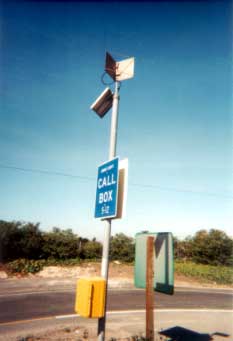
Figure 15-9: Call Box
- Cellular telephones. This method of incident detection is becoming more important resource as the number of cellular telephones on the roadways increases. Some traffic management systems, in coordination with enforcement agencies, have established free cellular call numbers for reporting incidents or requesting aid. These toll free numbers connect the caller directly to the traffic management center or to other agencies responsible for responding to incidents.
- Freeway service patrols. Another effective method for monitoring traffic conditions and detecting incidents is freeway service patrols. A freeway service patrol consists of a team of trained drivers who cover a particular area of freeway, monitoring traffic operations. Many different vehicles are used for freeway service patrols around the United States, including light trucks, mini-vans, and tow trucks. The most noticeable benefits of service patrols are those involving traffic incident management, as discussed in Chapter 10, Traffic Incident Management herein.
- Call boxes / Emergency telephones. Call boxes or emergency telephones (Figure 15-9) may also be used to detect incidents or to locate motorists in need of help. These devices are located on the side of the freeway and are typically spaced from 0.40 km to 0.80 km (0.25 to 0.50 mi) apart. Motorists can stop and use these devices to report a problem.
15.2.9 Video Surveillance
Closed circuit television (CCTV) systems have been used for many years to provide visual surveillance of the freeway system. Control centers typically use CCTV systems for the following purposes:
- Detecting and verifying incidents.
- Monitoring traffic conditions
- Monitoring incident clearance.
- Verifying message displays on changeable message signs.
- Monitoring environmental conditions (e.g., visibility distance, wet pavement).
For fixed location CCTV systems, video cameras are permanently mounted either on existing structures along the freeway or on specially installed camera poles (see Figure 15-10). This type of system consists of various components, including the following:
- Video camera unit.
- Mounting structure (existing or newly installed).
- Controller cabinet housing the camera monitoring and control equipment.
- Communication system connecting camera to control center.
- Video monitors and camera controls located in control center.
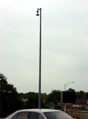
Figure 15-10: CCTV Camera Assembly (Courtesy of Wisconsin DOT)
CCTV systems allow control room personnel to visually monitor sections of roadway and to react directly to the actual conditions on the roadway. Since operators can lose interest if required to constantly view CCTV monitors, and may fail to notice incidents immediately after they occur, current systems are being designed to automatically position cameras at suspected incident locations (as signaled by incident detection algorithms) and to alert the operator.
15.2.9.1 Cameras
Current CCTV technology allows viewing of ¼ to ½ mi (0.4 to 0.8 km) in each direction if the camera mounting, topography, road configuration, and weather are ideal. The location for CCTV cameras is dependent on the terrain, number of horizontal and vertical curves, desire to monitor weaving areas, identification of high-incident locations, and the need to view ramps and arterial streets. Each prospective site must be investigated to establish the camera range and field-of-view that will be obtained as a function of mounting height and lens selection.
Two key measures of CCTV camera operation are light sensitivity and camera resolution. Sensitivity describes the amount of light needed to make a useful image, while resolution is the number of lines reproduced from the camera signal in making a video image on a monitor useful. The amount of available light is one of the most important factors affecting CCTV camera performance in traffic applications. Therefore, cameras must be sufficiently sensitive to view traffic conditions during morning and evening peak periods, even in winter when illumination may be very low during morning and evening "rush" hours. Light levels at intersections and interchanges typically range from 2 to 3 foot-candles (FC), while light levels can be less than 0.1 FC at roadway sections between intersections / interchanges. Cameras should also provide good horizontal resolution since this parameter helps determine image quality and ability to discern details. This is particularly important for viewing at a distance.
Video cameras compatible with National Television Standards Committee (NTSC) standards are available in either monochrome or color. Traditionally, monochrome cameras offered better resolution in low-light conditions, although improvements in color video imaging and processing technologies have closed that gap. In general, monochrome cameras have several advantages over color cameras. Specifically, monochrome cameras:
- Perform well under a greater variety of light conditions, including infrared;
- Are more light-sensitive overall;
- Provide higher resolution;
- Have a higher signal-to-noise ratio;
- Last longer; and
- Cost less than color cameras.
Monochrome cameras require illumination at the faceplate of only 0.13 FC, equivalent to full moonlight, to produce a full video image. For an 80% video level, monochrome cameras require 0.01 FC at the faceplate, equivalent to a clear full moon, and 0.0016 FC, equivalent to a clear quarter moon, to achieve a 30% video level. A 30% image is recognizable in black and white.
In contrast, color cameras require a minimum illumination of 0.8 FC at the faceplate, equivalent to the ambient light level at sunrise or sunset, to produce a full video image. For an 80% video level, color cameras require 0.07 FC at the faceplate, equivalent to twilight. At this level, however, the camera image may not reproduce color effects properly. Color cameras generally require full-spectrum illumination for proper color rendition. Further, good color saturation (intensity) is important in a color camera. Insufficient color saturation results in a "washed out" image, and over-saturation can make an image appear excessively vivid. Color camera resolution is 480 TV lines horizontally and 350 TV lines vertically.
The performance gap between color and monochrome cameras is converging to the point where, except for the most demanding low-light situations, differences in video quality and resolution are indistinguishable. Color cameras have a distinct advantage over monochrome cameras in providing color information that can aid incident verification, assessment and management. Color video can also integrate visually with other color graphics and workstation displays. Although the ability to reproduce color at low-light levels diminishes significantly, color cameras can easily differentiate headlights, taillights and red brake lights in low light. In areas of consistent traffic, vehicle headlights should illuminate the field of view sufficiently to benefit from a color CCTV system.
Another strategy for CCTV surveillance in low-light conditions is using cameras with adjustable shutters (integration cameras). By slowing the shutter speed, adjustable cameras can increase frame exposure times allowing more light to reach the camera image-sensing device. The tradeoff of slower shutter speeds in a high motion (i.e., moving traffic) environment is a blurred image. The improved visual presentation and additional information color video provides outweigh possible quality erosion in low-light levels. Further, in an arterial application where street lighting is used, low light level presents are less of a risk.
Both analog and digital cameras are marketed for freeway management application, as summarized below:
- Analog. The main component for analog cameras is
the Charge Coupled Device (CCD) sensor. The CCD sensor is a solid-state
imaging technology available in a compact, inexpensive format. CCD cameras
are typically available in a variety of imager size formats, including
2/3", 1/2", 1/3" and ¼". The two most common, proven CCTV camera
sensors are the interline transfer and frame transfer CCDs. Both CCD
devices provide good quality video and good sensitivity.
- Interline CCD is the most commonly used system type for security and surveillance applications in traffic management, mass transit, airports, and military applications. Interline CCD sensors are smaller than frame transfer imagers, have longer service life, require less periodic maintenance, produce no geometric distortion, are immune to vibration, magnetic fields and direct exposure to sunlight or headlight, and consume minimal power. The interline transfer CCD image device eliminates overload streaking because it is not sensitive to infra-red, improves dynamic range, and also provides high resolution.
- The frame transfer CCD imaging device provides extraordinary resolution, and is very well suited to full-motion video monitoring under consistent illumination levels. However, the frame transfer device uses larger individual photocells and is thus more sensitive. The frame transfer device requires a larger chip area, so it costs more and has a higher level of "smear" than interline transfer devices. Smear occurs when an illumination source overloads the imager, resulting in the appearance of bright vertical lines on the image. Both types of CCD devices have some smear, but it is more pronounced in the frame transfer device.
- Digital. An alternative to analog video technology is Digital Signal Processing (DSP), which is becoming a traffic management standard since the cost of the technology has dropped over the last 5 years. DSP magnifies a CCTV image through a process called "electronic zooming", which increases the effective zoom of a camera by up to 8 times. This process is basically enhanced "pixel replication," a process using pixels more than once in creating output images. Electronic zoom increases the display size of only a portion of the camera sensor area, however, and resolution actually decreases during DSP because fewer sensor pixels make a display covering the entire monitor screen. The expanded image is actually an "artificial zoom," and lacks the resolution of an optical zoom. Other features of DSP are image stabilization and scene brightness balance.
15.2.9.2 Lens
CCTV system lenses are available for purchase separately from the camera. Since the lens is a vital component in determining CCTV surveillance range, it is prudent to consider lens capabilities separately from the camera. Of course, evaluation of any camera-lens pair is also necessary before recommending a particular lens-camera combination. It should also be noted that, while it may be prudent from a maintenance standpoint to standardize the lenses used, each application (location) has unique characteristics that will define the optimum lens.
The focal length of a lens (typically measured in millimeters) measures the distance from lens to camera imager, and determines the camera field-of-view. As focal length increases, the viewing area decreases and is magnified, making distant objects appear larger. Short focal length lenses have a wide field of view and display more of a scene. Long focal length lenses have a telephoto effect and provide more detailed views of distant targets.
Field of view (i.e., the height and width of a scene) and depth of field (i.e., the minimum and maximum distances from the lens at which a subject is in sharp focus) are two major considerations in selecting a camera lens for CCTV traffic applications. The following equations illustrate the relationship between focal length and object area using the typical ½" format imager (Note: The field of view for the same focal length lens differs depending upon the format imager):
| H = (6.4 x L) / F | F = lens focal length in mm H = horizontal dimension of the object in mm |
| V = (4.8 x L) / F | V = vertical dimension of the object L = distance from the lens to the object in mm |
Typical CCTV camera lenses come in a variety of configurations. For example:
- Lenses are available in ¼", ½", 2/3" and 1" formats compatible with camera imager formats.
- Zoom lens magnification ratios range from 6:1 to 22:1, depending on the focal length range.
- Common zoom lens focal length ranges are 4–86mm, 8–48mm, 8–80mm, or 16–160mm.
- Using a camera and lens of the same format size (for example, ½") results in a focal length equivalent to that of the lens.
- Adapting larger format lenses to smaller format cameras will result in a corresponding increase in the effective focal length of the lens. This is one way to extend the range of a given lens.
- Extenders placed between the camera and lens can also increase focal length by a factor of 1.5 to 2.0.
The amount of light a lens can collect is important in selecting a camera-lens pair. The lens F-stop measures the amount of light that can reach a sensing device through the lens, and is equivalent to the focal length divided by the aperture. The higher the F-stop number, the less light is transmitted through the lens. Zooming a lens out for distance viewing, or decreasing the aperture, will increase the F-stop resulting in less light being collected by the lens.
Zoom lenses also come equipped with pre-set capabilities. Potentiometers coupled with motorized zoom and focus functions provide position feedback to the Camera Control Receiver/Driver (CCR/D). This feature allows users to position cameras quickly and effortlessly at pre-set positions, a vital function for long-distance viewing at maximum lens zoom. With so much magnification, slight changes in camera position can change the camera view dramatically. In addition, presets are necessary for applications providing control over the Internet or other non full-motion solution.
Neutral Density (ND) lens spot filters are required in outdoor camera applications to prevent iris shutdown in the presence of bright point sources of light. Infrared (IR) lens filters are also required for use with color cameras to prevent distortion of the visible color spectrum.
15.2.9.3 Pan & Tilt
Using a pan/tilt (P/T) platform, CCTV system operators can change camera position about the 360-degree "azimuth" axis, and adjust camera elevation up or down (within a 90 degree range). Together with a zoom lens, the P/T allows operators to view a scene within any direction about the camera, and within the lens field-of-view and distance ranges. Adjustable limit switches on the P/T restrict the range of motion to that required for a particular installation (or to block out certain views, such as residential areas). The speed of the pan/tilt mechanism determines the rate of camera coverage, while horizontal and vertical camera movements determine the coverage area.
P/T is accomplished with either an external unit that the camera, lens, and enclosure attached to, or a "dome" where the camera, lens, and P/T mechanism are enclosed in an aesthetic dome enclosure. External units typically have a pan speed of 6.0 to 9.0 degrees/second (plus or minus 1 degree), and a tilt speed of 4.0 to 4.5 degrees/second (plus or minus 0.5 degrees). However, one manufacturer has recently introduced a high-speed pan/tilt drive with a maximum pan rate of 40°/second and a tilt rate of 20°/second and a continuous 360° pan range.
Dome enclosed systems provide much higher P&T speeds – typically able to pan and tilt at 90-100 degrees/second. Dome systems also have more range than external units, having the ability to look straight down. It should be noted that the Dome cameras are "horizon limited". They can't look up at the sky or up a nearby steep hill very well. However, unless the camera is to be placed in very hilly terrain, this is not a major drawback for roadway traffic monitoring. Cameras in a dome system cannot be seen by motorists, which make them much less intrusive than external P&T systems.
Like the lens pre-sets, pan/tilt pre-sets allow pre-positioning cameras at desired locations. Pan/tilt pre-sets can also "reset" cameras to revert to a pre-determined direction at the end of a viewing session. This procedure can ensure that cameras are not left pointing in an undesirable direction. Like the lens pre-sets, the P/T pre-sets use potentiometers to feedback relative azimuth and elevation position to the CCR/D (Camera Control Receiver/Driver).
15.2.9.4 Environmental Enclosure
An environmental enclosure is usually necessary to protect delicate camera and lens equipment from environmental hazards such as weather and pollution. As with P/T units, the enclosure can be a separate component housing the camera and lens and mounted on an external P/T unit, or a dome enclosure housing the camera, lens and P/T mechanism. Each of these enclosures can be:
- Atmospheric vented enclosures are generally less expensive than others, provide better cooling, and require relatively little maintenance, or
- Self-contained, pressurized enclosures provide better camera and lens protection because the units are sealed. However, they do not provide the same level of cooling, and require periodic re-pressurization.
On the component enclosure, an externally mounted sun shroud, shading the camera housing from direct sun, can reduce internal temperatures by about 10 to 15 degrees Fahrenheit. The shroud also helps deflect sun glare and rain from the enclosure window. On a dome system, the dome itself is the sunscreen. An internal heater can help prevent fog formation due to temperature and humidity differentials on the front enclosure window or dome.
15.2.9.5 Camera Control Receiver/Driver
A Camera Control Receiver/Driver (CCR/D) decodes camera, lens and P/T control commands into control signals that the individual devices use during operation. The CCR/D can also manage zoom lens and P/T pre-set positions. CCR/D units typically store up to ten programmable pre-set positions by associating lens and P/T potentiometer settings with a given position. Each pre-set position defines a complete setting. The CCR/D uses this information to drive lens and P/T motors to acquire that position. Fully variable control of all P/T azimuth positions is also possible by associating potentiometer readings with compass point directions. This option allows finer camera control, but with greater complexity and expense. Preset positions are repeatable up to one degree of accuracy.
Scene blocking is another CCR/D feature that may be desirable for freeway surveillance. Using this feature, an operator or system administrator can program a section of the viewing area to be blocked out during panning operations. Scene blocking can prevent operators from viewing inappropriate areas such as private backyards, apartment buildings and hotels. A variation of this feature freezes the image as the camera pans across the blocked viewing area and resumes normal real-time viewing when the camera reaches the end of the blocked area. In external P/T units, physical "stops" are installed on the unit to prevent the unit from panning or tilting beyond a determined point. In either case, these settings are typically performed at initial set-up, and seldom require any further maintenance.
15.2.9.6 Video Communications and Formats
Video can be transmitted either as analog or digital video. Transmission of analog video requires large amounts of bandwidth. For transmission distances of more than 500 feet, analog video must usually travel over coaxial cable or fiber optic cable.
Digital video requires that the analog video source be converted to digital "data". This is accomplished via a CODEC (coder-decoder). The process is very similar to the conversion of voice from analog to digital, but is substantially more complex. Several different types of video CODECs are available to serve a wide variety of communication needs. The CODEC provides two functions. First, it converts the analog video to a digital code. Second, it "compresses" the digital information to reduce the amount of bandwidth required for transmission. In the process of converting from analog to digital and back to analog, the video image loses some quality. The compression process also adds a small loss of video quality. Each of the following CODECs has its own set of video image quality loss characteristics.
- H.261 CODECs are used primarily for video conferencing. The analog to digital process sacrifices motion for video and audio quality. They typically use POTS (or DDS) services to reduce total cost of operation and are designed to provide simultaneous multiple connections for group conferencing. However, they can use T-1 and "fractional T-1" circuits for better image quality.
- DS-3 CODECs were developed for use in distance learning systems, providing full motion, full video and audio quality for the classroom situation. Communication is accomplished via broadband links. The communication links can be leased DS-3 service, or privately installed copper or fiber optic networks.
- JPEG (Joint Photographic Group Experts) and Motion JPEG are some of the most widely used CODECs for video surveillance purposes. However, they were primarily developed for the purpose of storing images electronically. Each still image is converted to an electronic data image and transmitted. The still images are assembled at a receive decoder and displayed at a rapid rate to provide motion. They can be used with POTS communication circuits, fixed low speed data circuits, or broadband copper and fiber optic communication links. They are also used in wireless applications such as spread spectrum radio, or CDPD cellular.
- MPEG (Moving Picture Experts Group) CODECs were developed to provide a better quality motion image compression. There is less image quality lost in the conversion and compression processes. However, the primary purpose of MPEG CODECs is to provide "real-time like" motion pictures via the Internet (also called Streaming Video). The overall process creates a storage buffer so that there is always a slight delay between the request to view and the start of the motion picture. For the average user of the Internet, this is not a problem. CODEC manufactures using the MPEG-2 standard for traffic surveillance purposes have adapted this standard to create a real-time video transmission. However, this does have a minimal impact on final image quality. The MPEG-4 standard was developed for Internet streaming video, but is also being adapted for "real-time" surveillance purposes.
15.2.9.7 Portable CCTV Systems
Portable CCTV systems can serve several purposes including the following:
- Short-term traffic monitoring in areas with non-recurring congestion (e.g., work zone, critical incident, detours etc.).
- Traffic monitoring at special traffic generators (e.g., stadiums, parades, etc.).
- Traffic monitoring along evacuation routes
- Determination of optimum camera location for fixed location CCTV systems.
Portable CCTV systems are typically mounted in a light truck or van or on a trailer (see Figure 15-11). Components of a portable system include the following:
- Camera with pan-tilt-zoom capability.
- Telescopic boom.
- Television monitor and video recorder
- Camera control unit for controlling pan, tilt, and zoom functions.
- Generator for powering equipment; or battery power with solar charging
- Air compressor for operating telescopic boom.
- Wireless communications
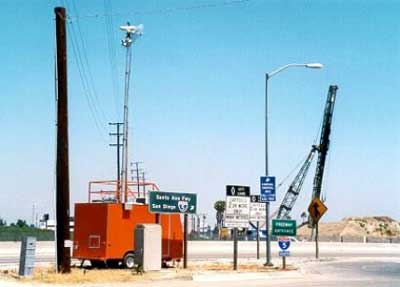
Figure 15-11: Portable CCTV Assembly
(Photograph courtesy
of Lawrence A. Klein, Placentia, CA)
15.2.10 Environmental Sensors
Observation and prediction of weather events and their roadway impacts are important in the development and implementation of operational strategies and response plans. Better road weather data (i.e., timely, accurate, and relevant) are critical to effective freeway management and operations in adverse weather. The type of weather event that is occurring will influence decisions of traffic managers. Weather events can range from relatively localized phenomena (thunderstorms, fog, and tornadoes) to major events that may require evacuation over a wide area (hurricanes, floods). Specific weather may vary over different parts of a network (rain, ice, snow) resulting in a need for different responses. Transportation managers need the ability to gather and process information on the location, characteristics, and duration of weather events, as well as the ability to predict their impacts (11).
Effective response requires that transportation managers be able to gather and process information that describes the key characteristics of a weather event. Operational strategies should reflect the best understanding possible of such weather event characteristics including:
- Severity – Precipitation type and amount, temperature, visibility, and wind speed are among the specific measures that will describe the severity of the weather event. The degree of potential risk to life and property will vary greatly and influence the response.
- Area of Impact – The size and characteristics of the geographic area impacted by the event will have a major influence on operational strategies. Weather events may influence an area beyond the range of individual jurisdictions, requiring additional coordination activities. A common terminology and clear understanding of weather events and their impacts are needed to define the area of impact.
- Time of Day – The operational strategies implemented will vary based on time of day. Events occurring during peak hours will require different, and more complex, strategies than those required during periods of light travel. Events occurring during morning peak will require a different response than those occurring during evening peak.
- Lead Time – The lead time prior to the weather event will influence the response of the transportation managers. Transportation managers need an understanding of forecast accuracy and risk factors in order to deploy the appropriate level of resources.
- Event Duration – The anticipated duration of the weather event, as well as the start and stop times, will also influence operational strategies. Contingency plans must be part of the strategy in case the event is either longer or shorter than anticipated. Events starting just prior to or during peak periods will require different response plans than those events that start during periods of light travel (11).
15.2.10.1 RWIS
A road weather information system (RWIS) is a combination of technologies that collects, transmits and disseminates weather and road condition information. The component of an RWIS that collects weather data is the environmental sensor station (ESS). An ESS is a fixed roadway location with one or more sensors measuring atmospheric, surface (i.e., pavement and soil), and/or hydrologic (i.e., water level) conditions (Figures 15-12 and 15-13), including:
- Atmospheric sensors – air temperature, barometric pressure, relative humidity, wind speed and direction, precipitation type and rate, visibility distance
- Surface sensors – pavement temperature and condition (dry, wet, ice, freeze point, chemical concentration), subsurface temperature, subsurface freeze/thaw cycles)
- Hydrologic sensors (stream, river and tide levels)
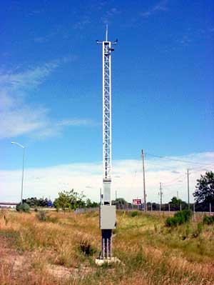
Figure 15-12: Environmental Sensor Station
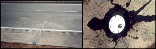
Figure 15-13: Surface Sensor
Data collected from environmental sensors in the field are stored onsite in a Remote Processing Unit (RPU) located in a cabinet. In addition to the RPU, cabinets typically house power supply and battery back-up devices. The RPU transmits environmental data to a central location via a communication system. Central RWIS hardware and software collect field data from numerous ESS, process data to support various operational applications, and display or disseminate road weather data in a format that can be easily interpreted by a user. Environmental data may be integrated into automated motorist warning systems, and transmitted to TMCs, emergency operations centers and maintenance facilities for decision support. This information may also be used to enhance forecasts and supplement mesoscale environmental monitoring networks (i.e., mesonets) (25).
Weather service providers (who are often RWIS/ESS vendors) also use the data to develop tailored weather services and products, including pavement temperature / bridge icing forecasts, ice and snow prediction, optimization of treatment routes and resource allocation, and thermal mapping. The latter is a process to quantify the variation in nighttime road surface temperatures across the roadway network. This variation can be 10°F or greater (depending on exposure, altitude, traffic, and road materials), which can impact which areas may become icy before others.
Transportation managers utilize environmental data to implement three types of road weather management strategies – advisory, control and treatment. Advisory strategies provide information on prevailing and predicted conditions to both transportation managers and motorists. Control strategies alter the state of roadway devices to permit or restrict traffic flow and regulate roadway capacity. Treatment strategies supply resources to roadways to minimize or eliminate weather impacts. Many treatment strategies involve coordination of traffic, maintenance, and emergency management agencies. Winter maintenance managers utilize road weather information to assess the nature and magnitude of threats, make staffing decisions, plan treatment strategies, minimize costs (i.e., labor, equipment, materials), and assess the effectiveness of treatment activities (by agency staff or subcontractors). Traffic managers may alter ramp metering rates, modify incident detection algorithms, vary speed limits, restrict access to designated routes, lanes or vehicle types (e.g., tractor-trailers) and disseminate road weather information to motorists in order to influence their travel decisions. Some Traffic Management Centers integrate weather data with traffic monitoring and control software. Emergency managers may employ decision support systems that integrate weather observations and forecasts with population data, topographic data, as well as road network and traffic data. When faced with flooding, tornadoes, hurricanes, or wild fires; emergency managers may use this data to evacuate vulnerable residents, close threatened roadways and bridges, and disseminate information to the public.
RWIS standards fall into the following three categories:
- Siting standards focus on installing ESS in locations that generate the most accurate and appropriate weather condition observations.
- Calibration standards are procedures for testing the accuracy of ESS observations.
- Communication standards include protocols for exchanging data between RWIS devices and other ITS elements, and display and message set standards for communicating weather and road condition information to end users.
The information requirements and spacing of information collection points for weather monitoring depends on a number of factors, including:
- Average annual precipitation – the greater the precipitation (e.g., snowfall), the need for more roadway information at closer intervals. Similarly, areas / segments with significant rainfall and / or icing potential (as determined from thermal mapping) will also need roadway information.
- Level of winter maintenance activities – an organization that regularly implements proactive treatment strategies (e.g., anti-icing before snowfall) will typically need more road weather information than an agency that performs reactive treatment (e.g., plowing and spreading abrasives after snowfall).
- Terrain – areas of higher elevation, with steep upgrades / downgrades, and/or plains subject to high winds and blowing snow, may need a greater coverage of weather information.
- Microclimates and thermal influences. Weather information is required wherever there is a significant change.
- Spot problems – areas with very local influences (e.g., fog, high winds, frequent icing) necessitate a focused coverage of partial weather information as a minimum.
Additional information on RWIS and ESS is available from the FHWA publication entitled "Best Practices for Road Weather Management, Version 2.0" (Reference 25).