Guidelines for Transportation Management Systems
Maintenance Concept and Plans
2. Maintenance Considerations and Activities
3. TMS Maintenance Concept & Requirements
4. Maintenance Considerations for the Life-Cycle of a TMS
6. TMC Maintenance Program: Multi-Year Plan
7. Maintenance Program Support Services
3. TMS Maintenance Concept & Requirements
3.1. Introduction
As defined previously, responsive maintenance is the repair or replacement of failed equipment and its restoration to safe, normal operation. Preventive maintenance is the activity performed at regularly scheduled intervals for the upkeep of equipment.
This chapter provides an introduction and overview of a maintenance concept and the linkage and traceability of the TMS maintenance concept to the Operational Concept for the TMS. The idea of a maintenance concept and a resulting set of maintenance requirements build on the proven Systems Engineering approach. The systems engineering approach is recommended as the preferred method for developing ITS projects with FHWA's Rule 940 (Ref. 3). Systems engineering is a structured technique for thinking about systems development and begins with a concept of operations. A "concept of operations" summarizes what the system is supposed to accomplish and under what conditions it will be done. From this concept, a set of requirements can be developed. It is these requirements that drive the rest of system design and implementation.
A "concept of operations" is designed to articulate the vision, roles and responsibilities, practices, and procedures to be realized in a TMS. Likewise, the "maintenance concept" is designed to articulate the essential reliability and performance measures necessary to meet stated operational concepts. Just as the concept of operations drives the system functional requirements, the maintenance concept drives the Maintenance Requirements. These maintenance requirements then become enabling requirements for input into the system design phase and other implementation and operation phases in the TMS life-cycle.
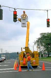
Figure 3-1 INFORM Maintenance
Crew at Work, NY
Several references from the literature research offer suggestions for maintenance programs, such as setting goals and objectives for a maintenance plan. Often, measures of performance are used to set maintenance levels or even as the basis for maintenance budgeting. These are very useful techniques; however, this approach can sometimes miss the bigger picture. For example, a maintenance goal of keeping 95 percent of all CCTV cameras available at all times does not answer the bigger picture of why are CCTV cameras needed in the first place, since there is no traceability back to the original concept of operations.
The main impetus for recommending a structured systems engineering approach for ITS project development was the need to improve the chances of success. Without a structured systems approach, ITS success stories, unfortunately, have not been a common occurrence. The systems engineering approach was originally developed in the aerospace industry in the 1960's to combat an alarming failure rate for large, complex missile and space programs. The systems engineering process does not guarantee success, but it has certainly improved the chances of getting there.
The systems engineering approach can also reduce costs. Another way of describing systems engineering is that it is a "requirements driven development process." That is, user requirements are the overriding determinant of systems design, component selection, and implementation. There should be no "gold plating" and you only pay for what you really need.
As stated earlier, there are precious few funds available for TMS maintenance. Any funding that may be allocated is done so only after a significant level of justification. Once allocated, most Agencies must be very judicious in spending their maintenance funds and often worry about how to set priorities so as to not overspend in one area at the expense of another. Thus, the maintenance concept is a central element of any maintenance plan or program. The maintenance concept imposes a structured approach to the development of maintenance requirements that is traceable back to an operational concept.
This chapter details the maintenance concept and parallel activities in the systems engineering process. The main objective of this chapter is to introduce and describe a relatively new process that is designed to overlay and parallel the basic systems engineering process. The steps in the maintenance concept development process are described in enough detail to allow application to a wide range of systems. An example is provided to illustrate a particular application of the maintenance concept to develop, justify, and estimate maintenance requirements.
3.2. What is a Maintenance Concept?
Since the maintenance concept is designed to complement the systems engineering process, it is useful to start with a brief overview of systems engineering. Figure 3-2 is a graphical illustration of the steps in the systems engineering process. This "V" diagram is one of many ways to depict the systems engineering process. This particular representation, however, is the model presented in the FHWA/NHI course entitled "Introduction to Systems Engineering."
Figure 3-2 Systems Engineering Life-Cycle Process D
Table 3-1 summarizes each of the steps in the systems engineering process outlined in the "V" diagram and identifies how each step can potentially impact the maintenance requirements of the system.
Step in the Process |
Description |
Implications for Maintenance |
|---|---|---|
| Regional Architecture/Vision | Not shown in "V" diagram, this is an input into the Systems Engineering process. | May require maintenance of external interfaces. |
| Concept of Operations | Articulates the scope and reason for the system, roles, and responsibilities for all stakeholders, including, but not limited to, practices and procedures, environmental and utilization requirements. | Operational, environmental and utilization requirements establish baseline maintenance requirements. |
| High-Level/Detailed Requirements | No technology selection yet. This is the "what" not the "how". Process of decomposing very high-level concepts into greater levels of detail. A walkthrough process provides validation that requirements capture the concept of operations. | Requirements such as reliability, systems life-cycle costs, and performance requirements directly influence maintenance requirements. |
| High-Level/Detailed Design | Includes the allocation of detailed requirements to system components or modules. This step describes "how" the requirement will be met. | This step provides the best opportunity to control maintenance costs through the design alternatives analysis. |
| Implementation | Implementation of the approved design. Construction and/or software development. | Inspection and process quality-assurance help minimize surprises in the testing phase. |
| Integration, Verification, and Validation Testing | Recomposition of subsystems. Testing for performance verification. Validation that design requirements met by integrated system. | Verification tests whether or not the system was built right. Validation tests if the right system was built. |
| Operations and Maintenance | TMS is commissioned and accepted. | Execution phase further validates maintenance requirements. |
| Assessment | A crosscutting activity that can be performed at any step, but typically done after commissioning (i.e., how well did we do?). | Maintenance experience will be useful for the next evolution of the system. |
| Traceability & Configuration Management | Another crosscutting set of activities that documents and maintains the linkage between all the steps in this process. | Provides the documentation roadmap to support and simplify TMS maintenance. |
Sometimes referred to as an "enabling requirement," an inherent system requirement is the maintainability of the system. By simply following the systems engineering process, systems maintainability and reliability can be captured in the design alternatives analysis. For example, a requirement for 99.9 percent availability of the system database computer has significant implications on the computer hardware and network design. Design alternatives such as redundant power supplies or redundant computers must be evaluated against the total system costs. The drawback of this straightforward approach is that that the life-cycle maintenance costs may not be fully considered during design. A low-capital cost solution for this example could be to utilize an off-site backup computer during a failure of the primary computer. Having multiple computers in multiple locations, however, can greatly increase maintenance costs by adding significant travel and lost time to everyday maintenance activities.
A more comprehensive approach is to develop a "maintenance concept" that parallels the concept of operations. Figure 3-3 shows the system engineering process along with and parallels the maintenance concept and requirements development steps. It is important to note that the maintenance concept does not require changes in the systems engineering process, but rather provides a way to emphasize maintenance within the context of the systems development process.
Figure 3-3 Incorporation of the Maintenance Concept into the Systems
Engineering Process D
The maintenance concept leads to high-level and detailed maintenance requirements. Implementation of the system coincides with implementation of the maintenance management program, which, in turn, provides verification that the system is maintainable as designed. The crosscutting activity of system validation during the operations phase parallels validation that the maintenance concept was captured in the management of the system and confirms that the maintenance requirements are being met.
Maintenance Requirements
The maintenance concept described above leads to a series of requirements for a maintenance plan. These requirements include:
- Configuration management and traceability,
- Qualifications of staffing,
- Planning a maintenance program,
- Risk management,
- Cost estimating,
- Measures of performance,
- Design life considerations,
- Partnerships, and
- Procedures.
These requirements are addressed in the sections that follow.
3.3. Configuration Management, Traceability, and the Maintenance Concept
There is growing recognition of the need for an on-going configuration management plan and process for TMS. Configuration management (CM) is defined as a process for establishing and maintaining consistency of a product's performance, functional and physical attributes throughout the product's design, implementation, operations, and maintenance phases (Ref. 4). The more complex a system becomes, the greater the range of variables that impact system performance. With more variables, the potential for permutations and variations on possible configurations grows exponentially. Without a rigorous configuration management process that documents all changes and modifications to the system, it is nearly impossible to diagnose what changes may have caused a system malfunction.
The maintenance concept and tracking of maintenance requirements relies on two key outputs of the CM process: baseline documentation and on-going performance monitoring. A baseline is any fully documented configuration found to meet current operational concepts and system requirements. Maintenance management systems (discussed in detail in Chapter 7) typically provide key performance indicators, such as mean time between failures (MTBF), mean time to repair (MTTR) as well as availability percentage for various system components. By pairing a baseline with a set of key performance indicators, a system operator can monitor selected measures and, if there is a problem, can very quickly narrow down the number of potential causes.
For example, the INFORM system on Long Island, New York tracks the percentage of devices online and maintains a trend analysis. Figure 3-4 shows the statistics for three years of operations. A configuration management process will keep track of the changes in the system and can be compared with the output of the performance monitoring process. Subtle changes in system availability or device performance may not be immediately obvious; however, they will likely be evident over the long term.
Figure 3-4 Three-Year Report of Equipment Availability D
Traceability is an important crosscutting activity in the systems engineering process. Its importance can be illustrated in the example diagramed in Figure 3-4. In this diagram of a vehicle detection subsystem within a TMS, there are certain wiring configurations in the field, which are eventually mapped to fields in the systems database. There is a typical wiring configuration, but the number of lanes can vary by location. There is a critical need for good up-to-date documentation of all of these configurations. The cost of maintenance or troubleshooting of this subsystem will increase dramatically if the system technician has to visually verify all cabinet wiring configurations before making database changes.
3.4. Sample Applications of a Maintenance Concept
Consider the following examples of how maintenance concepts can parallel the development of operational concepts:
Figure 3-5 Importance of Traceability and Configuration Management
to the Maintenance Concept D
An Agency is considering the implementation of adaptive traffic signal control to help with arterial congestion. The initial concept of operations is to upgrade all of the Agency's signals to adaptive control. As the concept is further defined into systems requirements, the maintenance concept is also developed. The maintenance concept recognizes that the new technology being proposed cannot impose drastically higher maintenance requirements on the Agency without some beneficial trade-offs. Adaptive control algorithms require significantly more detector data to operate successfully. More detectors will require a higher level of field maintenance. Prior to completing the final design, the scope of the adaptive control project is scaled back to just the critical intersections. Even though there will be some increase in field maintenance of the new detectors, this effort is offset by better performance through the critical intersections and reduced engineering time revising timing plans. In this example, the feedback from the parallel development of a maintenance concept and requirements has resulted in a refined concept of operations and related system requirements that are more in tune with both the operational and maintenance funding of the Agency.
In another example, an Agency is designing a new freeway management system and requires a method of verifying reported incidents and determining appropriate response measures. A closed-circuit TV (CCTV) camera system is selected through the design process. The design alternatives analysis recognizes that even good quality CCTV equipment occasionally fails for one reason or another. Research has indicated that large systems can expect an average of 5 to 10 percent failures. For example, for a 50-camera system, between two and five cameras will not be operational at any given time. Based on an operational concept that requires "full CCTV coverage" of the roadway, the designer has to consider the maintenance concept required to meet this requirement. One alternative is to increase maintenance funding to procure additional bucket trucks and CCTV spares to enable faster responsive time and more rapid repairs, thereby reducing the average number of failed cameras. Assuming the initial funding could be obtained, the total life-cycle cost of maintaining such a resource would be much greater than the cost of repairs. A re-evaluation of the design is a better solution. Adding a few more cameras and adjusting their locations to provide for more overlap of CCTV viewing angles will reduce the probability that any single camera failure will result in significant blind spots. Even with a few more cameras to maintain, there is less of a requirement for a large maintenance fleet and spares inventory and the total life-cycle costs are reduced.
3.5. Planning a Maintenance Program
In the planning of a maintenance program, a very important issue is the acquisition of a consistent budget stream to continue the upkeep of the various systems and devices. Some Agencies have limited their approach to extended warranties and sometimes one or two years of additional support from the system integrator to maintain the computers and software. As with other highway programs, maintenance costs are a significant percentage (around 5 percent) of the capital costs. However, using a fixed percentage for cost estimation of maintenance is not a very reliable process. The variations in functionality, weather, and geography among differing systems necessitates that cost estimates be made on a case-by-case basis. Also, planning a maintenance program needs to include an estimate of the staffing requirements. One way is to use a spreadsheet that calculates the maintenance labor hours necessary for preventive and responsive maintenance activities. The table (Ref 5) indicates Maintenance Staffing levels in variety of TMS's.
| Boston | Toronto | Long Island | Detroit | Milwaukee | Atlanta | Phoenix | Houston | |
|---|---|---|---|---|---|---|---|---|
| Number of Maintenance Staff | N/A | 3+ | N/A | 3 | 3 | * | 3+ | 3+ |
| Organization Responsible for Maintenance | Installation Contractor | Agency, Contractors | Maintenance Contractor | Agency District Office | Agency District Office, Communication & Maintenance Contractors | Agency, System Manager, PM Contractor | Agency District Office TMC Systems Team | Agency District Office |
| Special Maintenance Elements | None | None | None | None | Information Technology Specialist | Information Technology Team | Systems Team | None |
| Centerline Miles | 7.5 | 60 | 165 | 180 | 63 | 220 | 254 | 122 |
| Types of Field Equipment | SCADA, VMS, Loops, CCTV, Gates, Over height, FO Network, AM/FM Rebroadcast | VMS, Loops, CCTV, FO Network, Ramp Meters, RWIS | VMS, Loops, CCTV, Coax Network, Ramp Meters, Traffic Signals | VMS, Loops, CCTV, Coax & FO & Microwave Network, HAR, Ramp Meters | VMS, Loops, Microwave Detectors, AVC, CCTV, Ramp & Freeway Meters HAR, RWIS | VMS, Loops, Radar, VIDS, CCTV, FO Network, Ramp Meters | VMS, Loops, PAD, CCTV, FO Network, RWIS | VMS, LCS, Loops, CCTV, Gates, FO Network, Ramp Meters |
TMC maintenance is not clearly separable from other maintenance functions. The types and number of devices that are included is site specific but using the brief definition of each spreadsheet column heading, below, a staffing estimate can be made. The column heading can include:
- Field Device: Is the ITS equipment and components out in the field?
- Device Count: Total count of devices.
- Preventive Maintenance Schedule: Total vendor-recommended periodic maintenance trips during the service period. Typically at 3-, 6-, or 12-month intervals.
- Labor Hours per Person: Labor effort needed to perform the recommended maintenance procedures.
- Number of Persons per Crew: Is Assess adequacy of the number of personnel and crews to perform the preventive maintenance procedures safely and efficiently.
- Travel Time One-Way: Average distance to be traveled one-way to the maintenance location.
- Labor Hours + Travel Time (Round-Trip): This formula calculates the total time in hours for the crew size and travel times.
- Total Hours for Labor/Travel and Devices: This formula calculates the total time needed to perform the preventive maintenance for each ITS field device type.
- Average Number of Responsive Maintenance Visits per Year: This average comes from other ITS Agency's maintenance reports and vendor information given for their devices.
A sample spreadsheet is shown in Table 3-3, below.
| Field Device | Device count | Preventive Maintenance
(Hours) |
|||||
|---|---|---|---|---|---|---|---|
| Preventive Maintenance Schedule | Labor Hours Per Person | Number of People per crew | Travel Time | Labor Hours + Travel Time | Total Hours for Labor/ Travel & Devices | ||
| Variable Message Sign | 25 | 6 months | 2 | 3 | 3 | 15 | 750 |
| Highway Advisory Radio | 5 | 12 months | 3 | 2 | 2 | 10 | 50 |
| Weather / Pavement Sensor | 10 | 12 months | 2 | 2 | 3 | 10 | 100 |
| Camera - CCTV | 40 | 6 months | 2 | 3 | 2 | 12 | 480 |
| Non-Intrusive Count Station (Video or Radar) | 60 | 12 months | 2 | 2 | 2 | 8 | 480 |
| Permanent Count Stations (Connected to STC) | 1 | 12 months | 1 | 2 | 2 | 6 | 6 |
| Permanent Count Stations (Not Connected) | 20 | 12 months | 1 | 2 | 2 | 6 | 120 |
| Video Detection at Signals | 20 | 12 months | 2 | 2 | 2 | 8 | 160 |
| Total hours | 2146 | ||||||
| Field Device | Responsive Maintenance (Hours) |
|||||
|---|---|---|---|---|---|---|
| Labor Hours Per Person | Number of People per crew | Labor Hours + Travel | Average Number of Visits Per Year (1/3 of Devices) | Total Hours for Labor/ Travel & Devices | ||
| Variable Message Sign | 4 | 2 | 14 | 8.3 | 116 | |
| Highway Advisory Radio | 2 | 2 | 8 | 1.7 | 13 | |
| Weather / Pavement Sensor | 2 | 2 | 10 | 3.3 | 33 | |
| Camera - CCTV | 2 | 2 | 8 | 13.2 | 106 | |
| Non-Intrusive Count Station (Video or Radar) | 2 | 2 | 8 | 19.8 | 158 | |
| Permanent Count Stations (Connected to STC) | 2 | 2 | 8 | 0.3 | 3 | |
| Permanent Count Stations (Not Connected) | 2 | 2 | 8 | 6.6 | 53 | |
| Video Detection at Signals | 2 | 2 | 8 | 6.6 | 53 | |
| Total hours | 534 | |||||
Supervisory staff are typically added according to local policies and conditions.
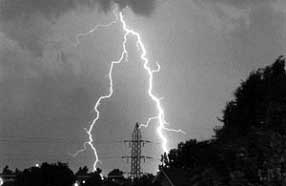
Figure 3-6 Lightning Causes EMP Damage Remotely
(Photo: FEMA)
TMS's are rarely static. If successful, they are liable to be expanded; if not particularly successful, they can be modified or replaced. In addition, due to budget constraints, the procurements are often made over several years. Thus, at any one time, there is often a varied mix of technologies and ages of equipment. For example, having a variety of message signs is common. In some cases, the manufacturer may have gone out-of-business — a fairly regular occurrence in this industry. This leaves the Agency with a confluence of devices: some new and possibly being maintained by vendors; others aging and possibly being maintained by Agency staff. In addition, there can be items that should be scrapped, but which are politically difficult to remove. This particularly applies to DMS's that drivers are used to seeing. Over the past decade, there have been several DMS manufacturers that have gone out-of-business, leaving Agencies with no sources for spares. In those situations, the best that can be done if items are not to be scrapped is to either selectively remove selected less critical components and use them for spares, or try to re-engineer replacement components.
Figure 3-7 Risk Assessment Matrix D
To mitigate these problems, a maintenance plan should incorporate scrapping items and ensure that spares and replacements are anticipated. Particular attention should be paid to DMS's and cameras since sign messages and video feeds to the public are quickly missed when either removed or non-operational. Budgeting for replacement items is the key to avoiding these problems.
Staffing Qualifications
All staffing associated with any TMS project must be qualified for the work that is to be performed. Typically technicians under contract that are responsible for the electronic components should have a minimum of a two-year associate degree plus two years relevant work experience or equivalent. This type of requirement should be included in any statement of work for contractors. An equivalent to this qualification would be more than five years of relevant experience directly with the Agency. A problem reported by some of the surveyed Agencies involved qualified staff being proposed by the winning contractor, but different, less capable staff being used on the job when the project began.
3.6. Risk Management and Probability of Multiple Failures
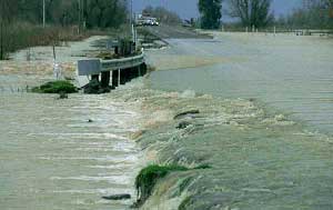
Figure 3-8 Flooding Damages ITS as well
as Structures
(Photo: University of Nebraska)
With regard to planning for knock downs, lightning, floods, and other unforeseen events, some allowance needs to be made. The FHWA guidelines require that roadside devices are either thirty feet from the carriageway or they are protected by a guardrail. One ITS system in Virginia with over 1,000 roadside devices suffers from approximately one knockdown per year.
Lightning is extremely variable and, despite the best attempts towards protection, electromagnetic pulses (EMP) can damage the electronics — even when the devices are not directly hit. In fact, most damage to equipment is not caused by direct lightening strikes, but by induced voltages on conductors from nearby strikes. ITS devices are often electronically sensitive devices placed in open areas on top of electrically conducting metal poles. To make things worse, these devices are often connected to both power and communication systems via long-conducting copper wires. There have been examples of ITS camera installations in Florida where all of the PTZ units were rendered inoperative by a single storm where the damage came through the power supply.
Flooding too can cause major problems to ITS devices. In Bombay, India, the controller bases are four feet high to protect them from the monsoons. Obviously, the risks to ITS components will vary significantly in different geographies and climates across the US.
Each Agency that is trying to assess the maintenance need could undertake a simple risk analysis whose objectives would be to:
- Identify those issues and factors that are liable to occur.
- Assess the costs associated with these factors.
- Determine appropriate mitigation solutions.
A simple assessment matrix can be used to assess the potential significance of each area of risk.
Each potential risk needs to be assessed for its probability of occurring and the costs. Information on historical weather patterns can be obtained from the National Environmental Satellite and Information Service (NESIS) at: http://www.nesdis.noaa.gov/. NESIS has significant information on weather history that may help in assessing the probability of events for specific states. Although the scoring of the probability can be arbitrary, the areas that are shaded indicate higher probability and higher cost impact. The information can be used as tool to assist in the evaluation and risk.
Knowing which areas are at-risk can assist in maintenance planning in:
- Design aspects that that will lower the impact of disasters. These could include raising elements above potential floodwater or increasing lightning protection.
- Making allowances in the number and types of spares that are needed.
- Having a contingency fund for exceptional conditions — similar to those that some states have for snow plowing during severe winters.
Although the approach to risk evaluation does contain a series of subjective estimates, it has been found worthwhile as it allows the plan development to consider the likelihood and consequences of these types of events.
3.7. Sample Costs
Table 3-4 indicates a sample of annual maintenance costs. Such numbers are often included with maintenance and are frequently not readily available.
| System | Annual Maintenance Costs ($000's) | # of Miles | # of Devices | Cost per Device |
|---|---|---|---|---|
| ODOT–ARTIMIS | 1,000 | 88 | 1,200 | $833 |
| VDOT–N. VA | 2,800 | 150 | 2,743 | $1,020 |
| Orlando | 150 (preventive only) | 39 | 223 | $672 |
| Caltrans (1) | 2640 | NA | 2212 | $1,193 |
Figure 3-9 Annual Maintenance Costs by Device Type D
Inspection of the data in the table above leads to the conclusion that average annual maintenance costs are approximately $1,000 per device. However, the majority of devices in these systems are traffic detectors that are fairly reliable. This value would not be appropriate for systems that contain a high number of devices that are more expensive to maintain. Daniels et al. (Guidelines for Funding Operations and Maintenance of Intelligent Transportation Systems/Advanced Traffic Management Systems, Transportation Research Record 1588) provided costs for maintenance by device type and these are shown in the Figure 3-9.
3.8. Traffic Operations and Maintenance Programs
Effective management of operations and maintenance staff must begin during the planning and design phases. This activity is particularly important in fostering an acceptance of the new traffic system among Agency personnel. Fear of the unknown, coupled with a potential misunderstanding of the system's purpose and concerns that personnel may have regarding job security, can detract from full and efficient utilization of the new system. As previously noted, the following opportunities for staff involvement can be provided through the pre-start-up process, thereby breaking down the natural barriers to system acceptance:
- Early involvement in system plans and designs to ensure proper consideration of reliability and maintainability issues.
- Assurance of thorough training tailored to staff needs.
- Participation in construction inspection and acceptance testing.
- Exposure to similar systems through field services with operations staff.
After the system is operational, several important management functions need to be completed. One is to schedule and conduct in-house, on-the-job training programs. This ongoing training is necessary because of personnel turnover, advancement of personnel to other positions, or terminations. Such a program should be initiated as soon as practical after systems implementation. The in-house training program can be supplemented by sending operations and maintenance staff to attend outside training or to visit similar systems, as appropriate.
At the San Antonio TransGuide Traffic Management Center, TMS operators have been successfully utilized in assisting experienced maintenance personnel in performing preventive, responsive, and emergency maintenance. TMS operators were also used in acceptance testing. The benefits of doing this include the following:
- Provide much-needed assistance to maintenance personnel.
- Provide in-house training for operators without additional cost.
- Give TMS operators a change of pace from their normal routine and help prevent operator burnout.
- Reduce equipment down time.
There are both operational and budgetary connections between a TMS operations program and its maintenance plan. Operationally, the staff in the control center needs to be aware of current and planned maintenance crew activities. Some activities require that specific devices be controlled from on-site. When communications to the central control system are disrupted (typically when somebody removes the plug to connect a local device), the central software should provide a communications failure message. Control software applications should have the ability to take specific devices off-line. This should be done prior to the maintenance tasks. Although contractors and maintenance crews can schedule their activities in coordination with the operators, these often do not take place on time. Weather and the demands of responsive and emergency maintenance disrupt schedules. It is recommended that the maintenance crews and the operators at the central control room be in voice contact through radios or cell phones at all times.
In addition, there are circumstances when the control system operators may wish to halt or divert the maintenance crew. Any presence on the highway can be disruptive to traffic flow. During the course of special events, is not a good time to perform maintenance. Cooperation between the two groups is needed to ensure that preventive maintenance tasks — and lower priority responsive maintenance tasks — are not being performed at inappropriate times.
With regard to budget, all new TMS items and functions need to consider both maintenance and spares. Spares become a major item within a maintenance program, given that much of today's hardware cannot be mended by the local electrical technician. Historically speaking, the replacement of small parts in electronics effectively disappeared as integrated circuits developed. Most components today are comprised of a series of integrated circuits soldered onto boards. This tendency leads to returning all components to the manufacturer. The manufacturer can replace some parts at the component level, but in many cases the pieces are scrapped and replacements furnished. To some extent, this trend leaves the electrical technician with an easier task in terms of replacing failed components. However, it does mean that the maintenance plan and its budget must make allowance for adequate spares. The range of 5-10 percent of all items is used for estimating the needs. This is not a trivial amount of money and it is worthwhile, during the development of maintenance plan, to develop data on the mean time between failures (MTBF) for individual components. Having this data, the Agency can then adopt a policy regarding the time period of spares they wish to keep on hand. For example, if the PTZ motors on camera mounts have an MTBF of six years and the Agency has 50 cameras, it can expect that 50/(6*12), or 0.7, motors will fail per month. If the Agency adopts a policy of maintaining six months of spares, it will need to keep five spare motors on the shelf. The hard issue here is arriving at good MTBF data. Products change and these types of information are often not readily available. In some cases, the manufacturer can assist. However, many specification sheets quote numbers based on calculations made for each component of the device which provides guidance, but does not account for the effects that various components may have on each other, such as heating.
Each Agency should attempt to develop MTBF data for the specific devices for several reasons, including:
- To assist in determining the number of spares to keep on hand.
- To determine ordering policy for obtaining components.
- To assist in the estimating of responsive maintenance calls.
- To provide feedback on how reliable individual ITS devices are, i.e., whether a change in supplier should be considered.
3.9. Maintenance Measures of Performance
The following parameters are useful data when evaluating products. Nevertheless, the reader of product specifications should be vigilant about marketing hyperbole:
- Mean Time between Failures: The average time between hours of exposure for all like products divided by the number of failures (Be advised that warned this is not the "design life."
- Mean Time to Repair: Number of hours to make good the failed item.
- Average Cost to Repair: Approximate cost to make the item fully functional again.
- Design Life: Discussed below.
- Salvage Value: Although often zero, this value can be important when upgrades are being made.
There is a second-hand market for traffic signal controllers. Reselling older hardware and replacing it with compatible new equipment can oftentimes be cheaper than developing software to control two different hardware varieties.
3.10. Design Life and MTBF
This type of information is available at some vendor's websites — this example is for industrial quality Ethernet switches:
"Based upon 1,715 units delivered to our customers in the first twelve months of manufacture. We computed an installed running time based upon the above conservative estimates of 2,810,808 hours. With only four applicable failures during this one-year period, the calculated MTBF is: 2,810,808 Hours / 4 Failures = 702,702 Hours MTBF."
Other examples quoted include:
- Industrial Video Cameras — 20-80,000 hours (2-9 years);
- Radar detectors — 100,000 hours;
- Video projectors — 30,000 hours; lamps — 1500 hours; and
- Uninterruptible power supplies — 100,000 hours
Design life and MTBF is not the same thing for all ITS devices. In some cases, equipment can last decades if it is well maintained and necessary repairs are made. For example, a truck will operate for decades if well maintained. However, to last decades it will need lots of tires and may need an engine. On the other hand, a hard drive, that may have a MTBF of 50 years, a design life of 5 years and a warranty for 2 years will cause an ITS system to crash and usually cannot be repaired. When considering the spares and replacements of ITS devices the developer of the plan needs to consider the most appropriate measure for that device on their facility. Taking one value for a whole system's lifetime, say 10 years, would overestimate the life of a hard drive and underestimate the life of a cherry picker. If spares inventory and replacement budgeting are being calculated, the design life needs to be used.
There is significant variation between similar products. The developer of the plan should attempt to determine the likely design life of the specific product. Generally speaking, components that move break first. Things that get hot also tend to have shorter lives. In traffic signal controllers, the power supply is the most unreliable component, followed by the load switches, then the conflict monitor. Electronic devices that are not switching power and have no moving parts can operate virtually indefinitely as illustrated by computers from the early eighties and amplifiers from the seventies. However, on these devices, knobs and drives usually have had to have been replaced. The impact of these effects should be considered in product selection. Although maintenance needs may be secondary to specifying a required functionality, if there is a choice between differing devices with similar functionality, then these effects on maintenance need to be considered.
3.11. Timely Responses
When specifying responsive maintenance time, Agencies have a tendency to require excessively rapid response. From the contractor's perspective, keeping staff available 24 hours per day seven days per week costs a lot of money. If the required response time is less than the time for the alerted worker to travel from home, then somebody is required to be on-site full time. One full time position requires five employees. This cost is generally too high for the benefit that will be achieved. Even if the TMC is operational at all times, the chances that a failure of a particular device will affect operations is low. When writing the scope of work for the maintenance component of a contract, the Agency needs to consider how the contractor is going to cost the response. Even if Agency staff are being used to react to responsive and emergency calls, there are often working rules that either prohibit this or require significant overtime costs to be paid.
A reasonable balance needs to be developed between timeliness and costs. Some Agencies use the following type of wording:
"The contractor is required to provide two years of maintenance on all elements of the system following acceptance by the State of each element.
The contactor shall provide one phone number that will be the State's sole contact point for requesting maintenance. The timing for the maintenance response shall begin with the phone call to the contractor. The contractor shall ensure that the phone is answered or a message system is always available.
The contractor shall be on-site and commence work within four hours of being informed by the State that a repair is required. Only business hours (7:00AM-4:00PM) will be counted for the maintenance response time."
Changing the various time periods within the above wording can be done to suit the Agency. Of course, the implications of the changes to the costs need to be considered.
3.12. Pre-Bid Meetings
A real understanding of the needs of the maintenance contract is critical to success in these efforts. In one Agency, a request for proposal (RFP) was developed and advertised with a non-compulsory pre-bid meeting. The contract was for two years of maintenance. One company attended the pre-bid meeting, but did not bid the job. A single high-end bid was received. Since one bid was not allowed, the procurement was suspended. At that point, a survey was made of all the potential contractors to determine why they did not bid and would they be interested in a new bid. Some stated that they missed the announcement; others said there was too much uncertainty. Thereafter, a meeting was held at the Agency facility where all potential contractors and their potential subcontractors were invited to discuss the upcoming procurement. This was not a pre-bid conference. The Agency described what was needed from the contractor and the scope of work was discussed. Several comments were made by the contractors that were used to modify the RFP in accordance with input from the contractors. These comments included the following:
- Contractors did not want to buy equipment using their money
to be reimbursed later by the Agency without some compensation.
This process reduces the credit available to the contractor
and, in some cases, it would be too burdensome on the contractors
(e.g., during those periods between major spares purchases
and submission of invoices). Their point was they did not
want to be the Agency's bank. A markup of the equipment
costs was subsequently permitted by the Agency.
- The original RFP asked that the work be done during an
extended standard workday. However, contractors wanted the
ability to work at nights and weekends in order to maximize
the usage of their labor and equipment. A cherry picker that
trims trees during the day can clean signs at night, thus
lowering costs.
- Contractors were very wary of their ability to meet response
times under system situations that could cause major failures.
These include snowstorms, tornados, and major power failures.
The RFP was modified to forgive response times during certain
conditions
- The original RFP was for a one-year contract that was annually
renewable. The contractor's could not obtain space (i.e.,
warehouse for inventory, an office, and parking) on annual
contracts. Most commercial real estate contracts are for two
or three years. Thus the contractors put the entire value
of the lease into the first year as they did not know if the
contract would extend to later years. The RFP was changed
to an initial two-year period that was renewable annually.
- Several contractors stated that they were interested in
only parts of the job, e.g., video or communications systems
only. Consequently, the meeting attendance list was circulated
to all attendees who were encouraged to form alliances in
order to provide responses to all the required functions.
- Additional minor changes were made — mostly relating to local conditions and some ambiguities.
A revised RFP was then published. A mandatory pre-bid meeting was convened and the changes to the solicitation were explained. Three bids were received and a contract was negotiated with the winning bidder that was approximately $2.5M less than the bid received prior to the revision of the RFP.
This process seemed successful in that a better understanding of the Agency's requirements was attained. Also, a reduction in risk on behalf of the contractor resulted in a better contract and saved money.
3.13. Partnerships
There are a variety of arrangements between government Agencies, institutions, academia, toll authorities, airports, and others concerning maintenance activities. For example, the City of Charleston maintains the ITS devices in Mount Pleasant and Goose Creek in exchange for funding contributions. New York State University provides maintenance of the video system for NYSDOT in Albany. The Ohio DOT and the Kentucky Transportation Cabinet own the ARTIMIS TMS under a bi-state agreement and contract out the maintenance, with the management of the contract alternating between the two Agencies. In Houston, TxDOT has a shared services agreement with the State Thruway Authority that covers maintenance.
The form of these agreements is also varied. Sometimes there are no written agreements at all, just an understanding concerning who will do what. In other instances, there are memoranda of understanding (MOU) between the parties that more formally spell out the relationships and responsibilities. In some cases, there are firm contractual documents definitively defining tasks and timeliness requirements.
Agencies should look closely at the functions and hardware that are in locales in an effort to find areas of cooperation not just in maintenance activities, but also in operations. Historically, the functions of traffic signal system maintenance have often been shared by adjacent jurisdictions, e.g., where the State traffic signal maintenance group may take responsibility for a county or a city within its boundaries.
The structure of these MOU's usually includes such items as:
- The nature of the agreement and the naming of the parties.
- The intent of the parties and a definition of the form of the agreement.
- A scope of services that states what is to be done.
- Separate sections on the responsibilities of each of the involved parties.
- The duration of the agreement.
- A termination clause.
- A definition of responsibilities for ownership and maintenance.
- Other legal sections on assignments, audits, discrimination and a signature section.
- Exhibits defining equipment, shared space, payments, scope, and responsibilities.
3.14. Procedures for Control Centers
When considering failures of components, the general rule "if it moves, it will break" still applies. Particular attention should be taken with hard drives that contain the critical data to enable operations. Hard drives are typically quoted with MTBF of 300,000 or 500,000 hours. These periods (34 and 57 years) are nonsense since such long lifetimes cannot be verified; also, the same specification sheets nearly always warranty the product for three years or less. Experience has shown that for new equipment that turns over every three years, about 2 percent of hard drives will fail per year. Although not a large percentage, this can have a devastating effect on operations. It is recommended that as part of the maintenance activities for the central servers and workstations, disk mirroring or other redundancy features be incorporated together with regularly scheduled back-ups. Additionally, making all hard drives "hot swappable" with a common specification will enable the maintenance staff to readily replace the systems most key component.
Central servers can also fail and there are a variety of approaches that can be taken to ensure fairly continuous operations. In order of increasing costs these include:
- Obtaining a Ghost image of the hard drive — this
is a direct copy of everything on the hard drive including
the operating system and all its patches. Such imaging enables
direct replacement of the system at the time the image was
made. This is a good maintenance action that is cheap and
can be performed regularly.
- Providing a redundant computer that has the operating system
(which can be copied from the Ghost image) and can replace
the server or workstation as appropriate. Such an approach
will only update the system status and its database files
since the last back-up. Most office systems currently operate
on networks and thus the redundant computer can be ready on
the network in anticipation of a failure.
- Providing a database replication process using the redundant
computer, but adding an application that copies the database
to the redundant machine at regular intervals. This provides
a high level of redundancy, but does not replicate the data
held in the machine's memory.
- Furnishing a "hot" standby so that a second machine is mimicking all the processes that are taking place on the primary machine. An additional application monitors the operation of the primary machine and automatically transfers control to the secondary machine when a failure is detected. This approach is expensive and is not available on all operating systems. It is usually considered too expensive for ITS applications.
Whichever option is chosen, there are back-up procedures that need to take place as part of a regular preventive maintenance schedule. These tasks need to be coordinated with the operators using the machines
Configuration management of the other components that require maintenance in the control center include:
- Video display units — the projection variety often go out of tune and require frequent adjustment to the projection devices. In some devices, tuning must be performed monthly; in others, it is never required.
- Server and workstation operating systems that may require updates and renewals of pertinent licenses.
- Application software that needs to have certain procedures, e.g., downloading logs, associated with traffic data files and operator actions. Some applications also require to be restarted on a regular basis.
- Replacing video tapes, CDs, and backup tapes in archiving systems.
- Checking weekly for security updates and virus software updates.
- Checking monthly to clear temporary folders and the various files produced by applications that are no longer needed.
- Maintenance of contact lists.
The processes involved with these maintenance tasks in the control center are specific to the needs of the individual component or the requirements of the software application. However, the developer of a maintenance plan will need to make allowances for these tasks.