Chapter 5. Telecommunications for Field Devices
Page 2 of 2
NTSC stands for National Television System Committee, which devised the NTSC television broadcast system in 1953. NTSC is also commonly used to refer to one type of television signal that can be recorded on various tape formats such as VHS, 3/4" U-matic and Betacam. The NTSC standard has a fixed vertical resolution of 525 horizontal lines stacked on top of each other, with varying amounts of "lines" making up the horizontal resolution, depending on the electronics and formats involved. There are 60 fields displayed per second. A field is a set of even lines, or odd lines. The odd and even fields are displayed sequentially, thus interlacing the full frame. One full frame, therefore, is made of two interlaced fields, and is displayed every 1/30 of a second (30 frames per second). |
Basic Video Communication Circuits
Most FMS and a few traffic signal control systems use CCTV cameras to support incident detection. The communications systems used for video transport are very similar to the basic communication links discussed previously. That is, they use a communication transmission device to convert the video signal to one that is compatible with the selected media.
There are several different methods used to prepare a video signal for transmission over a communication link. The most common is to convert it to an analog electrical signal and transmit via coaxial cable. Most video originating from the type of cameras used in an FMS can travel about 100 to 300 feet without degradation (depending upon the specifications of the cable). To travel longer distances the system must include amplifiers. Triaxial cable can usually provide distances of up to 1000 feet without an amplifier.
All CCTV cameras used in North America provide an electrical video signal that meets standards developed by the National Television System Committee (NTSC). This standard is used by many other countries, including Japan, South Korea and Mexico. The NTSC standard is in part based on the 60 Hz AC electrical power provided in the United States, and was developed to provide a standard for broadcast television. The standard was adopted for use in CCTV systems. Two other standards exist – PAL and SECAM – based on the electrical standards in other parts of the world.
Analog Video
NTSC video can be transmitted via twisted pair, but not very far (a few feet). A standard telephone voice call (including low speed analog data used by traffic control devices) can be transmitted almost 20,000 feet. The difference is the amount of bandwidth used by the two signals. NTSC video requires between 3 MHz and 6 MHz, and a voice call requires less than 4 KHz of bandwidth.
The following table provides a comparison of voice, video and text transmission requirements:
Note: "Hertz" is a unit of time to describe the frequency of occurrence. "Bit" and "Byte" are units of data. |
CCTV cameras used for security and traffic incident detection do not output full broadcast quality signals and therefore do not require as much bandwidth. However, it is still greater than 4 MHz.
Most of the CCTV camera systems deployed in the 1990s used analog transmission systems with either coaxial cable or fiber optic cable. They were generally deployed in a configuration that used one communication link for each camera. As system operators gained knowledge of the video systems, they recognized that video signals could be multiplexed, allowing four (4) to sixteen (16) cameras to share a common communication link. Each camera could send a full video signal using a common coaxial cable (or fiber optic cable), and each could be displayed on individual monitors at the TMC. One of the drawbacks to this arrangement was that each video signal had to be brought to a communications hub for multiplexing. However, there was a significant savings for the total cost of the communications infrastructure. Figure 5-14, is a block diagram representing the basic elements of a frequency division multiplexing system.
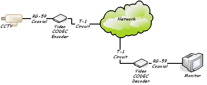
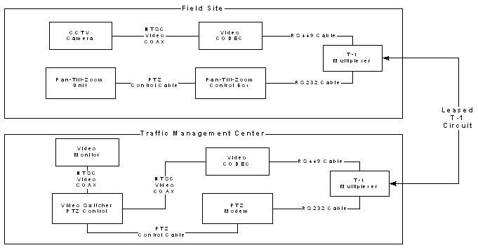
Video signals can also be converted to a digital signal in the same manner as voice is converted. A voice signal is digitized into a 64 Kbit/s signal and can easily be transmitted via two twisted pair for up to 6,000 feet. However, a full NTSC video signal requires a 100 Mbit/s signal and will not travel more than a few feet over the same two twisted pair cable. In fact twisted pair is not used for DS-3; carriers use coaxial cable, or fiber. Full bandwidth video signals don't travel very far (100 to 1000 feet) over coaxial cable. Transmitting video for any significant distance requires the use of a Video CODEC (coder/decoder). This type of CODEC is designed to use a DS-3 communication circuit. The DS-3 circuit is the equivalent of almost 45 Mbit/s. The reduction of the bandwidth to less than half of what is normally required is barely noticeable and in fact is used by broadcasters to send programming between television stations. DOTs have traditionally not used DS-3 CODECs because the cost of deployment was significantly greater than using the FDM type systems described above. DS-3 video CODECs have been in use for many years for "Distance Learning" programs and video conferencing. Many DOTs have deployed video systems using T-1/DS-1 communication links. Figure 5-15 is an example of a typical Video CODEC system using a T-1.
Digital Video CODECS
In the 1990s, DOTs began to deploy video CODECs that could use DS-1 communication circuits (see figure 5-15). Telephone companies provided lower cost (than DS-3) services and the DOT could install twisted pair infrastructure within their own rights-of-way.
Several different types of video CODECs are available to serve a wide variety of communication needs. The CODEC provides two functions. First, it converts the analog video to a digital code. Second, it "compresses" the digital information to reduce the amount of bandwidth required for transmission. In the process of converting from analog to digital and back to analog, the video image loses some quality. The compression process also adds a small loss of video quality. Each of the following CODECs are used in DS-1 systems and has its own set of video image quality loss characteristics.
- H.261 CODECs are used primarily for PSTN based video conferencing. The A to D process sacrifices motion for video and audio quality. They typically use POTS (or DDS) services to reduce total cost of operation and are designed to provide simultaneous multiple connections for group conferencing. However, they can use DS-1 and "fractional DS-1" circuits for better image quality.
- JPEG (Joint Photographic Experts Group) and Motion JPEG are some of the most widely used CODECs for video surveillance purposes. However, they were primarily developed for the purpose of storing images electronically. Each still image is converted to an electronic data image and transmitted. The still images are assembled at a receive decoder and displayed at a rapid rate to provide motion. They can be used with POTS communication circuits, fixed low speed data circuits, or broadband copper and fiber optic communication links. They are also used in wireless applications such as spread spectrum radio.
- MPEG (Moving Picture Experts Group) CODECs were developed to provide a better quality motion image compression. There is less image quality lost in the conversion and compression processes. However, the primary purpose of MPEG CODECs is to provide "real-time like" motion pictures via the internet (also called Streaming Video). The overall process creates a storage buffer so that there is always a slight delay between the request to view and the start of the motion picture. For the average user of the internet, this is not a problem. CODEC manufacturers using the MPEG-2 standard for traffic surveillance purposes have adapted this standard to create a real-time video transmission. However, this does have a minimal impact on final image quality. The MPEG-4 standard was developed for internet streaming video, but is also being adapted for "real-time" surveillance purposes.
Pan-Tilt-Zoom Issues
The use of pan-tilt-zoom (PTZ) created another problem. These devices use either a direct electrical signal with variable voltages, or special coding to activate one of the functions. The manufacturers of the PTZ devices developed special modems that convert the PTZ signal to an RS232 data stream so that it can be transmitted via standard communication circuits. This requires a separate communication path. Incident management systems built during the 1990s generally required separate communications equipment for both the video and the PTZ control. Originally, CCTV camera manufacturers offered an external converter. One was required at the camera end and the other with the video switcher at the TMC. Today, manufacturers offer products that combine both in one system using a single communication path. Most video CODECs and Fiber Video modems have a PTZ data port as part of the package, and cameras and switchers have the control signal conversions devices embedded. The video signal and the PTZ signal travel in opposite directions allowing full bandwidth to be provided for the video signal.
Video-over-IP (VIP)
The video systems described previously were developed to work over communication networks that existed to process voice communications. All data and video transmissions have to be adapted for transport over large point-to-point communication networks. This requires a significant investment in transmission hardware and software systems and media infrastructure. Ethernet and VIP help to reduce the overall complexity of the communications networks and significantly lower the cost of hardware and infrastructure required to support the system. One of the major benefits is the relative ease with which video can be distributed to desktop computer workstations. Before discussing VIP, a quick look at how TV cameras function.
Distributed computing and the explosion of the Internet have driven the use of internetworking for over 30 years. Practically every network in place today was engineered based on standards and technology optimized for handling the single data type, character data, that was prevalent as recently as 10 years ago. Today's sophisticated applications often require networks to handle video, storage and IP/Telephony. The speed and bandwidth requirements for applications using these data types are so high that most network technology is simply not up to the task. DOTs implementing new Advanced Transportation Management Systems (ATMS) are looking to new data communication technologies to help simplify their networks, and reduce the overall costs of deployment and maintenance. Ethernet for general data communication and video-over-IP are logical choices. The next few pages will look at the deployment of Video-over-IP.
TV cameras were first designed using an image pick-up tube. The face of the tube was coated with a light sensitive film that captured the image. The film created an electrical charge which was captured as an analog electrical signal. The electrical representation of the image was transmitted to a monitor. The output of the camera was an analog video signal. All of the equipment described above was needed to convert the video image to something that could be transported via the existing network infrastructure.
In the early 1990s, the "Charged Coupled Device" (CCD) was perfected. A CCD is an electrical device that is used to create images of objects, store information (analogous to the way a computer stores information), or transfer electrical charge (as part of larger device). It receives as input light from an object. The CCD takes this optical input and converts it into an electronic signal – the output. The electronic signal is then processed by some other equipment and/or software to produce an image. The camera must convert the digital image to an analog TV signal.
Initially, video transmitted via the Internet, was required to be converted from analog to digital, and then compressed for efficient transmission. VIP was created as a protocol for the efficient transmission of video via the internet (more about video over the internet and streaming video in Chapter 9). Some enterprising engineer recognized that cameras with CCDs were already capable of providing a digital image signal that was compatible with the digital display output of a typical desktop computer. CCTV cameras are manufactured today with a direct IP output. They can be directly connected to a communication circuit capable of carrying IP traffic. The image data from the camera can be directly routed to a desktop computer.
Two types of basic VIP circuits can be used for video surveillance and incident detection in an FMS or traffic signal control system:
- Direct VIP CCTV camera to Desktop Work Station
- Analog CCTV camera to Desktop Work Station.
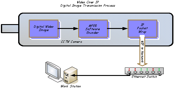
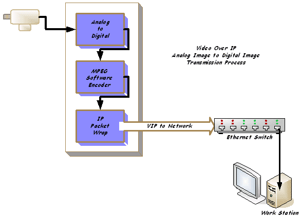
The first is very simple (as shown in figure 5-17), and the second does not have a high degree of difficulty. The direct system uses a camera that is designed to provide a direct output to an Ethernet. The digital video signal is compressed using an MPEG software encoder, and then wrapped in an IP packet for transmission. The second system (as shown in figure 5-18) requires a video CODEC that is designed to take the analog output of an existing CCTV camera, convert it to digital, encode the signal, and wrap it in an IP packet for transmission. There is no need to convert the video signal back to analog. Just use any media viewer application with a compatible MPEG software decoder.
Converting an existing system to VIP is relatively simple. Replace existing Video CODECs (or FDM modems) with a VIP CODEC. In most cases (note: replacement of an FDM system requires additional consideration of communication equipment), the existing communications cable infrastructure can be kept in place. Chapter Seven provides a description of the process used by Utah DOT to update its ATMS system to VIP. In the process, they were able to eliminate an expensive analog video switcher, and conveniently distribute video to multiple traffic, transportation and public safety agencies.
Basic Traffic and Freeway Management Networks
Basic Device Networks
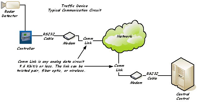
Note: Figure 5-19, is a basic network diagram for the listed devices. However, each device is unique and requires a specific set-up. |
The following systems all require the same type of communication circuit – low speed (9600 Bps or less). Some devices are connected via dial-up and others via private leased-line. RWIS systems normally communicate via a wide area radio link – a typical communication circuit diagram is provided below.
- Dynamic Message Signs
- Loop detectors
- Radar detectors
- Video detectors
- Remote Weather Information Systems (RWIS)
- Ramp Metering
- Pavement Condition Sensors
These devices all send or receive short (a few bytes) messages (e.g.: status, condition measurements, temperature, volume and speed, etc.). Most communication links are similar to those used by traffic signal controllers. One significant note is that RWIS sensors, very often, are located in remote areas without easy access to power and communication utilities. The preferred communication link is wide area radio. Wide area radio uses frequencies in the same range as Police, Fire, or Highway Maintenance vehicles. The systems use a fixed low power radio with a very directional antenna. The FCC has specific rules for using these types of radio systems on a secondary and non-interfering basis. The radio frequency availability and the rules for use are listed under "Title 47 CFR 90.20".
A communication engineer must be aware of all of the devices that will be deployed in the system. Each type of device has a set of communication requirements. The key differences are the frequency of communication, and the amount of data to be transferred. These factors are multiplied by the total number of devices to help determine the amount of required bandwidth.
This section dealt with basic communication circuits for traffic signal control, video incident detection, and generic traffic devices. The next section will provide a look at how all of the circuits are integrated into a single communication network. The principles of multiplexing described in Chapter 2 will be applicable.
Complex Communication Networks
Let's take a look at communication networks that support a complex traffic management system (an ATMS) combining traffic signals, CCTV cameras, dynamic message signs and radar detectors used for traffic volume and speed monitoring. A series of basic system design criteria and block diagrams will be created. Each will eventually become part of the requirements and specification documentation that is presented to potential engineering services, systems integrators and construction services vendors. Following is a typical scenario:
The basic system is planned for a major arterial that connects a suburban community to a major urban center. The overall route is 10 miles with a traffic signal system at both ends of the arterial, some low points that flood during frequent heavy rain storms and a total of six travel lanes throughout the arterial system.
The local DOT wants to optimize the traffic signal operation in both the suburban and urban areas adjacent to the arterial. They will utilize information collected from the arterial traffic flow radar speed and volume detectors at various points along the arterial. Additionally, the DOT will monitor for traffic incidents using radar detectors and CCTV cameras, and be notified of flooding conditions during rain storms via RWIS sensors.
The DOT has specified that it does not want to construct a private communication network. There is easy access to communication facilities adjacent to the arterial that can be leased from "LocalTel".
The engineer developing the communication network will create several diagrams to assist in overall system design. One of those diagrams should be a private system alternative to provide cost comparisons.
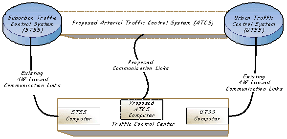
First, the engineer will create an overview block diagram to help visualize the relationship of the primary connection points. The communications engineer will also draft a narrative of the overall system - actually a statement of understanding, or concept of operations (from a communication perspective):
"The proposed network will provide communication links to connect four (4) primary elements: existing suburban traffic signal system; existing urban traffic signal system; proposed arterial traffic control system; proposed central traffic control center. In addition to existing 170 type traffic signal controllers, the D.O.T. is proposing to add CCTV, changeable message signs, speed and volume detection equipment, deer crossing sensors, RWIS sensors, connectivity to the internet, and communication links to a regional traffic advisory network. The proposed system will replace existing copper communication links with fiber and make use of spread spectrum radio to link remote devices. New traffic signal control computers will be placed in the proposed TCC. The existing traffic signal control computers will remain in place as backup servers."
This paragraph is reviewed by the project team for concurrence or changes. A block diagram representing the statement is created as a visual aid.
Next in the process is the creation of an overview of the major systems. The overviews include simple block diagrams and a brief written description of the system.
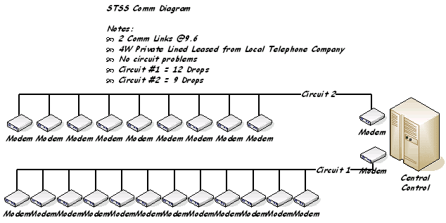
Suburban Traffic Signal System (figure 5-21): "The town of Nowheresville has an existing traffic signal system with a total of twenty-one 170 Type signal controllers. " The system is deployed using two 4-wire 9.6 Kb/s multi-drop circuits leased from the Nowheresville Community Telephone Company. Modems used in the systems operate in a half-duplex mode. The traffic signal controllers are deployed in a 10 square block area of the community with the controlling computer located at 5th & Arch Streets.
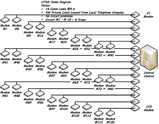
Urban Traffic Signal System (figure 5-22): "The city of Wearegreat has an existing traffic signal system with a total of one hundred twenty (120) 170 Type signal controllers. The system is deployed using fifteen (15) 4-wire 9.6 multi-drop circuits leased from the Verybig Telephone Company. Modems used in the systems operate in a half-duplex mode. The traffic signal controllers are deployed throughout the city with the controlling computer located at Broad & Main Streets."
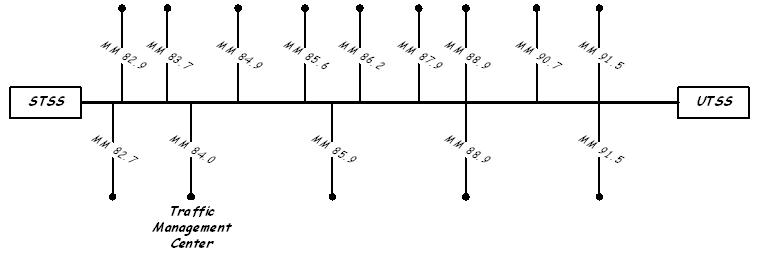
The next set of schematics is for proposed systems. There is less detail because the systems that are represented do not exist. The engineer may put in some information about the communication circuits, but realizes that they will change as the development process continues. The following schematic (figure 5-23) shows the proposed connecting arterial management system. The objective in the "first pass" at the system design should be generic making very few assumptions about the technologies that will be deployed. A database is developed using mile marker indicators as a reference for where equipment will be located. The requirements document should indicate the type of devices that will be deployed with approximate distances. The project team (including the communications engineer) should complete a field survey to pinpoint device locations. This will be critical for the communications system. The communication system designer will have to assure that there is enough signal strength. In addition to the device location, the table should also list approximate data bandwidth requirements.
A straight line communication diagram (figure 5-23) is created from this information. The table and the straight line diagram help to provide the communication engineer with a better understanding of where devices will be placed.
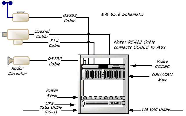
The communication system engineer creates a block diagram for each site to show how each device will be connected to the TMC. The diagram contains all necessary information and details the communication links and the type of connections for each device. A written description of the site details is also provided. Here's an example based on MM 85.6:
"The site at MM 85.6 will contain one CCTV Camera with PTZ side mounted at the 20 foot level of a 30 foot pole, an RWIS system will be placed on the top of the pole, and a radar detector will be side mounted at the 15 foot level. All of the communications equipment will be placed in a cabinet at the base of the pole. The communications cabinet will contain a Video CODEC which will have an RS 232 port for the PTZ. The cabinet will house a CSU/DSU multiplexer with four data ports. The primary communication link to the TMC will be a leased DS-1. A utility demarcation point will be placed within 50 feet of the site. The DOT will run necessary communication cable and power cable from the site to the utility demarcation."
The written description of the site helps to clarify what is needed, and prevents a misinterpretation of the schematic diagram.
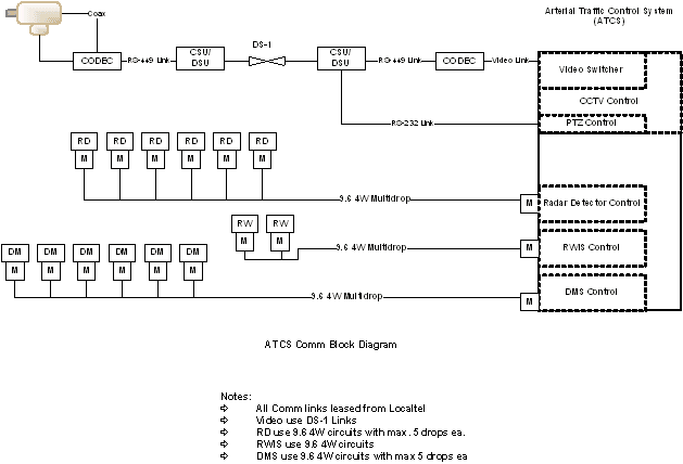
Notice that the site at 85.6 has multiple devices and takes advantage of hardware that can provide multiple communication ports via the single DS-1. Also, a 170/2070 controller is not included. Some traffic control software may require the use of a controller. This system is however, incident based. That is, the radar detector provides data that indicates the speed of traffic at a specific point. The central computer reads the data and alerts operators to take action. For locations with a single device, a specific type of circuit can be leased. Another alternative can be used. Multidrop circuits for each type of device can be run to each site, and DS-1 circuits can be run to the CCTV sites. This will add equipment and complicate some of the communication systems. However, if one type of communication circuit has a problem, the others keep functioning.
Following is a block diagram (figure 5-25) for an entire system using device based communication circuits:
Summary
Traditionally, transportation and construction engineering documentation is a series of technical drawings with material and construction specifications incorporated as part of the PS&E information. A plan set for a lighting pole (for example) will contain all of the information required for the contractor to provide and install. The dimensions, weight, wind-loading and mounting information can be specifically quantified and shown in the plan set. Minor deviations from standards can also be shown. Actual written instructions and other requirements are kept to a minimum. There's no instruction manual provided by the manufacturer that explains how to install and maintain the lighting pole.
Telecommunications systems have the same type of requirements for documentation. However, remembering that telecommunications equipment is primarily designed for Carriers, there is additional documentation that is supplied, and necessary for installation and optimization. Hardware manufacturers provide a complete installation and maintenance manual with every device (or every 10 devices if ordered in large quantities). Make certain that the documentation manuals are kept, and that there is a set (in a weatherproof pouch) at every equipment cabinet, plus a master set at the TMC.
A typical modem can be set to run at a fixed data rate, or allowed to adjust the data rate based on communication link conditions. If you don't specify this in writing, there's a fifty percent chance that the installer will be wrong. This will delay the overall project and cost money to correct.
SONET multiplexers, Ethernet routers, spread spectrum radios, modems, etc. are manufactured to fulfill a number of different requirements. Make certain that your communication engineer provides enough information for installation personnel to properly setup and optimize the equipment in your freeway management and traffic signal control systems.
Network Topology
A network can be defined as a link between any two points (or more) that mutually relies on the presence of the other. Communication points are normally referred to as nodes or hubs. Simple networks are developed to establish a temporary communication path, such as a basic telephone call. Complex networks are designed to provide a permanent communication link and have alternate links to protect the viability of the network. Freeway management systems typically use a complex communications network.
Many types of networks can be defined for telecommunications, each with a different purpose. Understanding the different types of networks is important. Each type of network has advantages and drawbacks. There is no "ideal" network solution that fits all situations. Consideration should be given to the ultimate requirements of the system that a communication network will support.
A "mesh" network may provide the ultimate solution for assuring that communication links will always be available. However, it is the most expensive network topology that can be established. Not assuring that communication links will be available when needed can also be expensive. Networks that support financial transactions require a high degree of reliability. The operators of financial networks will tend to require a highly redundant communication system. The telephone companies and long distance carriers have developed highly redundant networks to make certain that communication links are always available.
Four basic network topologies with many variations can be described to meet requirements.
- Point-to-Point
- Star
- Ring
- Mesh
Point-to-Point Networks
Point-to-point is the simplest. Start at node 1 and connect to node 2, then 3, and continue. Communication is serial and passes through each node. Lose any one node or link, and communication can be disrupted.
Star Networks
A Star network is simply a multipoint communication system that allows one node to communicate with many nodes (or many to one). This is also referred to as a "one-to-many" system. 10Base-T Ethernet is an example of star network. The LAN in your office has a router hub that connects all desktop computers to file servers and printers.
The star network allows any point to communicate with any other point in the network. However, if the central hub is taken out of service, then the entire network is out of service.
Ring Networks
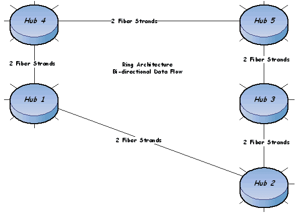
Ring networks are designed to overcome the weakness of the point-to-point system. Placing the nodes so that they can always communicate with an adjacent node helps to assure an available communication path. Fiber Optic systems are generally deployed using a ring network topology. SONET multiplexer hardware is designed to facilitate various types of ring networks. Two basic ring architectures are available with many variations and combinations that can be developed.
Uni-directional – the communication signal always travels in one direction around the ring. If any single node or path link is disrupted, communication between the other nodes continues in a serial path around the ring. A single strand of fiber can be used to for this type of network.
Bi-directional – the communication signal can travel in either direction. This allows the system to manage signal flow and determine the most efficient path. Two strands of fiber are used. One strand is the transmit, and the other is used for receive. Add more pairs of fiber strands, and the system will support dedicated hub-to-hub data flows.
Mesh Networks
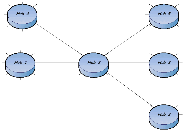
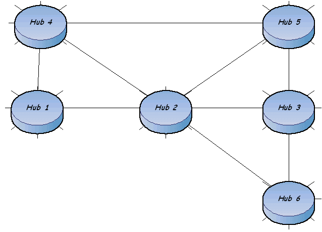
Mesh networks are a combination of the star and ring topologies. They can provide multiple communication paths for all nodes in the system. A ring network basically provides for one or two communication paths for each node. A mesh network can be designed to provide three, four, five, or more communication links for each node. How many is dependent upon the amount of money available and the willingness to manage and maintain a very complex communication system.
Note that these network topologies are independent of the media being used for transmission. Most of the more complex network topologies are used with fiber. However, microwave systems are also arrayed in star, and ring topologies, and basic Ethernet local area networks use a star configuration. New generations of wireless networks are being developed using a mesh topology in order to assure connectivity. That is, wireless customers will be able to access a network via more than one wireless base site.
Network Redundancy
How much redundancy is needed in a communications network? There is no simple answer or magic formula. One answer may be to ask how long your system can be down before operations are affected. Another answer might hinge on whether parts of your system can be out of service and not effect operations.
The mesh network shown above has multiple communication paths to each hub. If full redundancy is required one set of communications hardware for each communication link at each hub is required, and don't forget to add redundant power supplies. This arrangement can be very expensive especially when you consider that mesh networks weren't developed to provide communication path redundancy. Mesh networks were developed to support the needs of the internet. Communication paths have bandwidth limitations and communications hardware has functional limitations. To assure that most users of the internet will have a high availability of service, mesh networks are used. Mesh networks help to share communication path loading. This assures that no single communication path will become a bottle-neck.
Using Mesh Networks for communication path redundancy also requires a very complicated "alternate routes table". You have to provide each Hub with the routes to use if the primary is out of service. This can create problems with data intensive applications.
Ring Networks were created to provide communication path redundancy. They are simple (compared to Mesh) to set up. There are no complicated routing tables. The hardware operating system is told to switch to the alternate path if communication is lost on the primary. The amount of hardware required to implement a Ring Network is less than a Mesh Network.
Conclusion
Development and design of a telecommunications system is an iterative processes. Each element is built upon a very specific set of standards and requirements. The use of any type of communications circuit to support a traffic or freeway management system should be based on a clear understanding of the requirements for such a system. The creation of a thorough set of system requirements is key to the design and construction of an efficient communications system.

