Chapter 5. Telecommunications for Field Devices
Page 1 of 2
Previous chapters provided a look at the terminology, technology and history of telecommunications as well as the need to create a viable requirements document. This theme is continued with a look at the primary building block of telecommunications systems – the communication circuit. Telecommunication technology, its use and deployment, is an iterative process with new building upon the old. This is the industry's (telecommunication) way of assuring backward compatibility, and the continuing deployment of available new technology. The diagram is a representation of the merging of voice and data over copper. Analog voice communications evolved to digital voice communications. One voice channel carried over a pair of copper wires evolved to hundreds of conversations over the same pair of wires. The use of copper as a communication medium evolved into the use of fiber. The change of technology was revolutionary, but the implementation of the change was evolutionary. No sudden and dramatic change from one technology or process to the next.
In the 1980s, that process changed. The convergence of events, technology developments, and action by the U.S. Department of Justice and the Courts precipitated a change in the corporate structure of the monopoly afforded to AT&T. The "telephone company" agreed to divide into several competing businesses. This created a competitive and open environment for the development of communications services and hardware that exists today. The basic developments and events:
- The "Carterphone" Decision of 1968 allowed end users to purchase and install telephone equipment from companies other than AT&T
- The microprocessor was invented in 1971
- Field trials by AT&T in 1977 proved that fiber could be used with transmission loss factors no greater than copper.
- The ARPANET – precursor to the Internet – was activated in 1969
- AT&T implemented a plan to break into 7 regional and independent telephone companies, plus a manufacturing company – in 1983.
These events, plus an overwhelming pent-up corporate and individual demand, converged to forge a new direction in telecommunications services and technology. However, corporate change and inventions did not minimize the desire to provide full backward compatibility with existing systems.
Telecommunication technology is a major element of the application of traffic signal and freeway management and Advanced Transportation Management Systems. The use of telecommunication technology as a part of traffic management systems has followed an evolutionary process. Early traffic signal systems – deployed 50 years ago – used available telecommunication technology. Systems being deployed today take advantage of new technologies while accommodating existing – or legacy – systems.
This chapter is devoted to a look at the specific communication circuit designs for traffic signal and freeway management systems. Much of the communication equipment used for both types of systems is very similar. There are application differences, but most of it is hierarchal and building block in nature. A common theme for all of the circuits is that they involve the use of a media or protocol converter. The flow is essentially from simple modem based systems using twisted pair, to fiber optics, and wireless, from analog transmission to digital transmission systems. From voice based communication protocols to Ethernet and Wireless Application (WAP) protocols. The examples provided in this chapter are the application of the technologies discussed in chapter Two.
Before discussing actual communication circuit types it is necessary to look at some of the basic elements of circuits, and then understand their use as part of a traffic signal or freeway management system.
Basic Communication Circuits for Field Devices
We start with basic twisted pair copper and progress through fiber optics and wireless communication technologies.
NTCIP is actually a suite of protocols providing support for many different aspects of transportation communication system requirements. |
A key factor in the deployment of traffic and transportation control devices is the use of NTCIP (National Transportation Communication Interface Protocol) communication protocols. The use of NTCIP protocols does have an impact on the overall design of a communication network. Two rules that must always be followed in the design of a communication network:
- All communication elements cost money
- All communication protocols cost bandwidth
Every item attached to a communication circuit has a monetary value. Therefore, complex is inherently more expensive. Always attempt to keep circuit designs simple. Recognize the total cost is not just for the initial hardware. There is an added cost of installation, optimization, maintenance and operation. Avoid using complex telecommunication technologies simply because they are the newest. The "latest and greatest" won't always provide a solution to the communication challenges presented by a new traffic system. Let a properly developed communication system requirements document be your guide.
Basic Circuit Types
This section provides a definition of the basic communication circuit types and a concept of where communication engineers start the process of system design. Chapter Two, presented a reference to directly connected and switched communication circuits. In fact, whether direct or switched, all communication circuits fall into one of three categories:
- Point-to-Point (see diagram) – the communication connection between two devices, or a device and a controller.
- Point-to-Multipoint (see diagram) – a communication circuit connecting multiple devices to a controller. This can also be referred to as Multipoint-to-Point – depending on your starting point.
- Multipoint-to-Multipoint (see diagram) – a communication circuit allowing many devices to connect to many devices; this type of system always involves a switch or router.
Figure 5-2, represents the three basic circuit types using modems as the end devices connected to private line communication links. There are many variations, especially when using dial-up networks, or intelligent switches and routers. For example, the internet is an example of a Multipoint-to-Multipoint circuit. Many individual home computers can connect to one, or many web sites via the PSTN. The same type of service is also provided via Cable TV networks using a combination of routers and broadband multiplexers.
The Design Process
The development of a communication system design is very simple and not very complex – especially if a good requirements document is available. Let's take a look at the process and the steps to creating the design. Assume that a requirements document has been created for a signalized intersection project. The document lists the following communication system requirements:
- Seven 2070 controllers placed as indicated in table
- Traffic signals at intersections automatically adjusted for timing parameters by host computer
- Traffic Signals receive commands via field controllers
- Host computer will poll 2070 controllers once every second with query for data & time hack.
- 2070 controllers will store data from signalized intersections until requested by host computer
- 2070 controllers must respond to host query within 20 milliseconds
- Notice that there is no discussion of the type of technology to be used.
This allows the communication engineer to make hardware recommendations based on the requirements.
Communication engineers will generally visualize the basic communication circuit design as a block diagram rather than a mechanical design. This helps to simplify the overall design process. During the initial meeting to review the project concept, communications engineers will usually create a "back-of-the-envelope", or "table napkin", sketch. This helps to facilitate the discussion and provide the system designer and "client" (the DOT) with general points of agreement.
Communications systems are designed from the ground up. First step is to lay out the points of communication – generally identified by location. Street addresses are preferred, however traffic management systems are deployed at intersections or points on a highway. Exact locations will be determined during a site walk through. A device location table for a traffic signal system may appear as follows:
The table is then laid out on a map to help identify exact locations and to provide distance measurements. The distance measurements between devices are required in order to determine "link loss". The communication engineer must know if the communication signal will need to be amplified to overcome excessive link loss. Distance measurements will also assist in the development of the construction budget.
Note: This is a "fictitious" example of a traffic signal control system for the purpose of demonstrating how to calculate data communication circuit requirements. |
Next, a device and bandwidth table is created. The table shows the amount of data per transmission by site. For this type of system, the host computer normally sends a "time hack" and requests that the field units send available data. The table becomes a database for the system configuration.
The communication engineer needs to determine the maximum amount of data traveling in any single direction. Based on the information in the table, the maximum amount of data flows from the field units to the host computer. The total is 6400 bits. Therefore, a 9600 Bps (9.6kbps) communication circuit can be used successfully.
From this information, a schematic diagram is created. The schematic helps the communication engineer visualize the relationship of all points of communication. Overall design of a communication network includes all devices and communication cable routes. Figure 5-5, might be considered as a cover page for a set of schematics showing greater detail.
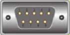
One of the drawings that should be included is a cable detail with a chart showing the connector pins. Very often manufacturers make their devices with a variety of cable connectors. Most computers use DB-9 connectors and modems tend to have either DB-25, or RJ45 connectors. If custom cables are needed, the cable connector and "pin-out" chart will save time and reduce confusion. If the Signal controller uses a DB-25 connector, and the modem has a DB-9 connector you should include a table that provides the following detail:
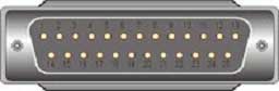
This chart is based on EIA/TIA standards for RS232 serial cables. Double check the standards for final reference and ask the device manufacturers to supply pin-out diagrams. Standards change, but a manufacturer may not have incorporated the changes.
This is a starting point in the overall design. As the process continues, the communication engineer will continue to refine the design until a reasonable conclusion is reached about solutions that will best support overall goals of the main project. A series of schematics are developed, and the design rules established in chapter Four are used to create a final design.
Traffic Control Device Circuits
Following is a description of communications circuits commonly used in traffic and transportation systems. At the conclusion of chapter Five we will provide an example of a complex communication system that incorporates a number of varying traffic and transportation system devices. Chapter Seven will present examples of actual systems that have been deployed (or are in the process of being deployed).
Earlier, communication circuits were described as having three (3) basic elements – transmitter, receiver, and transmission medium. That description was given to provide a basic understanding of communication circuits. Communication circuits have another element in common – protocol conversion. The most elementary system – two (2) tin cans and a string – has this element. The tin cans convert sound to a vibration which is transferred to the string. A basic telephone converts the human voice (sound) to an electrical signal (protocol conversion). The electrical signal is transmitted via copper wire (media). The electrical signal is received by another telephone and converted to sound. A modem converts the data protocol from a computer to a protocol that can be carried over a media. Modem is a contraction of the phrase modulator/demodulator. The modem converts the binary one/zero data protocol of a computer (or other data device) to a protocol that can be carried via a specific medium (11). Modems have been developed for twisted pair, radio, and fiber optic.
Traffic Control System
Remember - software and data protocols are stated in bytes, but communication transmission is stated in bits. 1200 bits of data is 150 bytes. One byte is equal to one character. Some traffic signal systems use a bit oriented message. The host computer is reading individual bits within a single byte to look for device status indications. |
Traffic controllers require a reasonably simple communication system. They are generally arrayed in a point-to-point, or point-to-multipoint serial network using low bandwidth, analog modems and twisted pair copper voice grade circuits. The greatest problem faced by a communication engineer in the design of these circuits is the polling requirements. Traffic signal systems are traditionally designed with system wide device polling every second. That is, every controller is polled once every second for information, and supplied with a clocking signal.
Consider a traffic signal system that uses a 9600 bps data transfer speed. If each device transmits 1200 bits of data per poll, then – theoretically – a maximum of eight devices can be connected on a single multipoint communication circuit. Allowing for round-trip delay or potential line problems, a communication engineer would only connect seven devices to each circuit. In theory, a signal system with 50 controllers would require eight individual multi-drop communication circuits.
If the traffic signal system uses a 10 bit message to provide all necessary information, a 9600 bps communication link could support a theoretical maximum of 960 field devices. The following formula is used: 9600 bits divided by 10 bits (each message) = 960. However, this figure is further reduced by the total time (round trip communication time) it takes to poll each device, signal attenuation based on distance, type and makeup of communication media, and the signal-to-noise ratio of the communication link. Additionally, there is the latency induced by a device to properly format and send a response.
If the system were using a byte oriented message, the maximum number of devices would be substantially less. A system that uses a message of 150 bytes would be limited to a maximum of 8 devices on a 9600 bps link - 9600 bits divided by 8 (one byte) divided by 150 bytes (each message) = 8. Make certain that the communication engineer and the software manufacturer coordinate these details. This will save time when the system is being optimized.
Basic Data Circuit Types
The following diagram illustrates the basic elements of a modem. In fact, DSU/CSUs, Network Interface Cards (NIC), Video CODECs, and many other transmission devices have these same elements. Key differences are based on the type of data interface and the transmission medium.
All communication circuits use some type of media – protocol converter so that device input/output can be transported via a specific media, or through a communication network. Examples are:
- Traffic Signal Control
- Communication Cabinet for Traffic Devices
- Variable Message Sign
- CCTV Camera
- PTZ Control
- RWIS Station
- High Water Monitor
The terms are also used in maintenance and installation manuals. Technicians are able to easily identify which side of the device is connected to the data equipment and which is connected to the network. |
When an engineer uses a modem they consider the device as an intermediary between the data equipment and the communication network. The computer (or other data device) is called the data termination equipment (DTE) and the modem is considered the data communication equipment (DCE). DTE and DCE are terms which help a communication engineer visualize a communication system in a technology neutral manner. The DCE device has two sides – DTE and Network. Using these terms, an engineer is able to visualize the orientation of the equipment to the network.
A CCTV camera is considered as a DTE device because it provides data in the form of an image. The camera is actually converting the image to and electrical signal which must be transported via a DCE device. The DCE device could be a modem that converts the video electrical signal to a T-1 signal for transmission via twisted pair copper wire. In this case, the DCE modem device is called a CODEC.
The communication system designer may prefer to create a system layout that is very generic. The designer can choose the technologies later in the process, but still has a working idea of how the system will be developed.
When finalized, the above circuit may appear as follows:
Basic Traffic Device Type Communication Circuits
Communication links for Type 170/2070 and NEMA controllers are fairly simple. Under normal operation, a 1200 bit per second two-wire half duplex circuit is used. Most systems are connected using an FSK communication protocol between the field controller modem and the master controller modem. A basic direct link between a single 170/2070 and a Master Control Computer would look as figure 5-11. Note that the private twisted pair cable installed by the DOT is described as a network.

Frequency-shift keying (FSK) is a method of transmitting digital signals. The two binary states, "0" (Low) and "1" (high), are each represented by an analog waveform. "0" is represented by a specific frequency, and "1" is represented by a different frequency. A modem converts the binary data from a computer to FSK for transmission over telephone lines, cables, optical fiber, or wireless media. The modem also converts incoming FSK signals to digital low and high states, which the computer can "understand." |
Modems use a specific modulation protocol to convert the digital output of a computer (or traffic signal controller) to analog for transport via a telephone line or twisted pair. The protocol used by modems for connecting traffic signal controllers to central control computers is FSK (frequency shift keying). Frequency shift keying accommodates low speed (below 9.6 KBps) data transfer. For higher data rates, other Modem protocols are used – PSK (Phase Shift Keying) and QAM (Quadrature Amplitude Modulation). If you want to learn more about these transmission protocols, consult any good telecommunications text book – there are several listed in the reference section of this handbook.
This basic communication system could be applied to almost any configuration. Substitute the 2/4 wire private line twisted pair with fiber and the basic network configuration does not change. The RS232 communication protocol used by the 170 controller would have to be converted to a light wave signal for transmission for transmission via the fiber. Decided to change to a newer 2070 type controller, but want to keep the existing twisted pair communication links? Just replace the controller, because the modems and transmission line remain the same. Note: This is assuming that there are no changes to the software protocols in the overall traffic signal system.
This arrangement (figure 5-13) can be used for multiple locations that require multiple point-to-point communication circuits. Each controller would have a direct link to the central computer and a dedicated communication port. Engineers would refer to this as a point-to-multipoint communication network. The use of many communication circuits, modems, and communication ports on a central computer can be expensive. Traffic signal systems tend to use a variant of the point-to-multipoint. This arrangement is called a multi-drop communication circuit. One modem at the central computer site serves many field modems. This scheme is especially cost efficient when leasing private line circuits from a carrier. The DOT pays for one communication circuit not the eight or more that it replaces.
"Delay" – for this purpose – is defined as the amount of time elapsed from central computer request for information until it receives information from a field unit. |
The central computer is controlling all of the communications process. It polls the field controllers for information, using a point-to-multipoint arrangement that allows all field units to respond individually. They have a virtual communication circuit to the central computer. Using the multidrop configuration allows the central computer to poll all of the field units attached to a single circuit, but each field unit must respond in sequence and cannot use the circuit while another unit is transmitting. Use of a multidrop arrangement requires close coordination between the communication system and the central computer software system. Make certain the communication engineer is fully aware of software communication delay requirements. If a field unit modem is sufficiently distant from the central computer, the software may have to be instructed to wait an additional one or two milliseconds for a response.
The DB-25 to DB-9 diagram table – shown earlier in this chapter – indicates a pin labeled "CTS". These initials stand for "Clear-to-Send". The field unit modem will wait for a Clear-to-Send indication before transmitting information to the central computer. If too much time has elapsed the central computer will complete another poll sequence. If there is too much delay, or the central has sent out too many requests for information, the central may assume that one or more field controllers have malfunctioned and issue an error report.
11. The plural term media is used because a modem can be used with many different types of media. It is the generic functionality of a modem that is being discussed in this section.