Appendix J: Converting Between Systems of Actuated Control Parameters
Most modern controllers use the cycle length, split, and offset (CSO) parameter system for specifying the actuated controller parameters that govern coordination. TRAFED uses the CSO system in its actuated controller dialogs. However, the CORSIM actuated control model uses cycle length, force-off, and yield point parameters rather than the CSO system. TRAFED automatically converts the CSO parameters to the parameters used by CORSIM in a process that is transparent to the analyst. However, for those who are interested in the process, the following discussion provides the mathematical details of the conversion process.
The discussion is based on an eight-phase, dual-ring actuated controller that is part of a progressive system of controllers. The intersection is phased in a quad left sequence as illustrated in Figure 94.
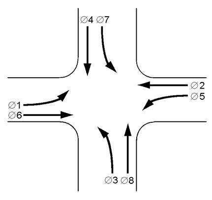
Figure 94. Diagram. Intersection phased in a quad left sequence.
Assume the controller is presently displaying green for the coordinated phases 2 and 6 (also noted as Ø 2/6). For ease of calculation, also assume leading dual left turn phasing, that the background cycle length is 100 seconds, the offset is 10 seconds (measured to the beginning of phase 2 and 6 green) and the splits are Ø1 and 5 = 10 sec, Ø2 and 6 = 40 sec, Ø3 and 7 = 15 sec, Ø4 and 8 = 35 sec. The respective vehicle clearance and minimum green times for the even number phases are 5 and 7 seconds and 4 and 4 seconds for the odd numbered phases. Clearance times include the yellow change interval and red clearance durations. Finally, assume the controller has progressed to the end of the coordinated phase, which (in CORSIM) is the yield point and the beginning of local controller time t = 0.
Converting NEMA Offset to Yield Point
In the example, as in most NEMA controllers, the offset is measured from the beginning of the system reference point, system T = 0, to the beginning of the coordinated phase green. In CORSIM, the offset value is measured from system T = 0 to the end of the coordinated phase green, i.e., the yield point. To translate the NEMA offset to the CORSIM yield point the following formula is used:

Figure 95. Formula. CORSIM yeild point.
The yield point cannot be larger than the cycle length or less than zero. If the calculation produces a value outside this range, the cycle length must be subtracted from the calculated value or, in the case of negative values, the computed value must be subtracted from the cycle length to produce a number within the appropriate range. Figure 96 presents a graphical illustration of the offset conversion.
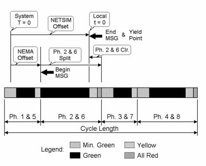
Figure 96. Diagram. NETSIM offset verus NEMA offset.
Converting Splits to Force-Off Values
Each non-coordinated phase has an associated force-off point. This is the point in the cycle where service for that phase must terminate to allow time in the cycle to service other non-coordinated phases and guarantee the return to the coordinated phases at the proper time in the cycle to maintain progression.
The force-off points are at the end of the phase extension green or if there is a pedestrian interval at the end of walk. Figure 97 illustrates the force-off points. Figure 98 shows how the force-off points are calculated from the split and clearance times.
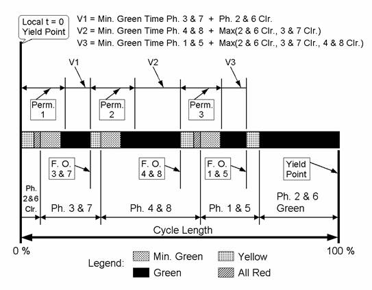
Figure 97. Diagram Signal coordination patameters.
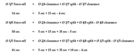
Figure 98. Equations. Force off calculations.
In the example, each pair of compatible phases (3 and 7, 4 and 8, 1 and 5) has identical force-off times. However, it is possible and common that compatible phases may have different force-off times. A lead-lag signal operation is a good example of this condition. However, the logic used in calculating force-off times can be applied to any phasing and timing scheme.
Computing Premissive Periods
There are several methods of assigning the phases that allowed to be serviced to permissive periods. When analyzing an operating controller, the method used should be determined and programmed into the CORSIM data set. Generally, this information is not easily obtained from controller displays and is typically programmed as a default condition chosen by the manufacturer. The best source for this information would be the local signal operations and maintenance personnel. If there is still doubt about how the phases are assigned, the following example seems to be fairly common practice.
In order for each signal phase to be serviced and the controller to return to the coordinated phase(s) at the designated time in the cycle, individual phases can only be allowed service during specific periods within the cycle and for specific duration. Permissive periods control when and over what time duration the controller is allowed to service non-coordinated phases. CORSIM allows up to three permissive periods to be specified as shown graphically in Figure 97.
In the example, the permissive periods will allow servicing of phases in order according to Table 44.
Permissive Period |
Associated Phases (Service Allowed) |
|---|---|
1 |
Ø 3/7, Ø 4/8, Ø 1/5 |
2 |
Ø 4/8, Ø 1/5 |
3 |
Ø 1/5 |
The permissive strategy presented in the table allows service to all non-coordinated phases during the first permissive period and is more restrictive during subsequent periods until the final period when service is allowed only to the phase that immediately precedes the coordinated phase. This assures that the coordinated phase will be serviced at its proper time in the background cycle. While this permissive strategy seems to be the most common, it does have one problem. If while in Permissive Period 1, a slight gap in traffic occurs on phases 3/7 and there is a call on 4/8, Phases 3/7 will be skipped and must wait for the next cycle to be serviced. An alternative to the above strategy, and one employed as the default by at least one major manufacturer, would be to only allow phases 3/7 to be serviced during Permissive Period 1, phases 4/7 during Permissive Period 2, and phases 1/5 during Permissive Period 3. This alternative strategy also allows the coordinated phase green to be extended into the normal time for phase 3/7 if there is no demand on those phases. This may be an advantage if the system green band width is limited by the end of the coordinated phase green.
The following paragraphs illustrate how to compute the permissive periods for the example using the strategy shown in the table above. In CORSIM, the times that specify permissive periods are relative to the yield point.
Permissive Period 1: In CORSIM, the start of Permissive Period 1 is always at the yield point and will always have the value of zero. The end of Permissive Period 1 will be at the point in the cycle where there is still sufficient time remaining to service the minimum green or pedestrian timing (whichever is greater) and all vehicle clearances. Thus, the end time for Permissive Period 1 is calculated as follows:
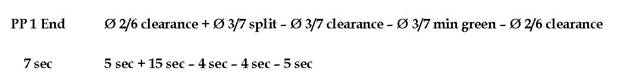 \
\
Figure 99. Equation. Permissive period 1.
Permissive Period 2: The start of Permissive Period 2 for the next non-coordinated phase will be at the force-off time for the proceeding phase. In the example, the beginning of Permissive Period 2 is at the force-off time for phases 3/7 or 16 seconds (see force-off calculations above). The end time for Permissive Period 2 is calculated as follows:
Figure 100. Equation. Permissive period 2.
The end of Permissive Period 2 can also be calculated using the previously calculated force-off times for phases 4/8, as follows:
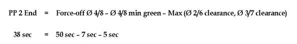
Figure 101. Equation. Permissive period 2 (recalculated).
Permissive Period 3: The start of Permissive Period 3 is the force-off time for the proceeding phase or Ø 4/8, which is 50 seconds (see force-off calculations above). The end time for Permissive Period 3 is calculated as follows:
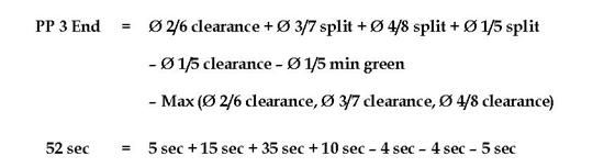
Figure 102. Equation. Permissive period 3.
The end of Permissive Period 3 can also be calculated using the previously calculated force-off times for phases 1/5, as follows:
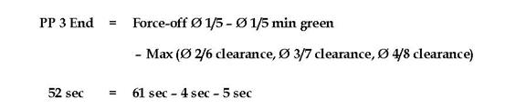
Figure 103. Equation. Permissive period 3 (recalculated).
Once a non-coordinated phase has received service from any permissive period, the remaining permissive periods in the cycle are omitted and the controller operates normally until the beginning of the next cycle when all permissive periods are again activated.