Model Systems Engineering Documents for Dynamic Message Sign (DMS) SystemsChapter 1. Concept of UsePurposeThe primary objective of this Dynamic Message Sign (DMS) Systems Concept of Use (COU) is to describe how the Systems Engineering (SE) Model Documents can guide the deployment of a DMS system ensuring the procured and deployed DMS system is successfully meeting the user needs of the stakeholders who will be using the DMS system to convey information to the traveling public. The purpose of the SE Model Documents is to guide the user through the process of developing systems engineering documents for definition and procurement of a DMS system. The DMS system may be a brand new deployment or an expansion of an existing system. The Model Systems Engineering Documents for DMS Systems are intended for projects with the following characteristics:
Agencies building large projects with custom software development or innovative applications will need to perform more detailed custom systems engineering, though these documents may provide an effective and time-saving starting point for that effort. The reference architecture for a DMS System along with the scope of the DMS Model Systems Engineering Documents is shown in Figure 1. As shown in Figure 1, the scope of the DMS Model SE documents comprises the DMS Management System, the DMS Controller, DMS Field Device or sign, as well as an optional Field Programming Terminal and optional External Devices. The interfaces crossing the dashed line are between the DMS Management System and the User, the DMS Management System and External Systems and between the Optional External Devices and External Systems. The DMS Management System is comprised of the server side processing and is connected to one or more DMS Controllers. Each DMS Controller is connected to one or more DMS Field Devices or "Signs". An optional Field Programming Terminal, either provided with the DMS Controller or a separate computer, allows field access to the DMS Controller to mimic the commands from a DMS Management System. Optional external device(s) connect to the DMS Controller and provide additional indicators and/or sensors involved with the DMS Field Device. Interfacing with the DMS Management System is the User and other External Systems. It is possible for an External System to also communicate with the optional External Devices. 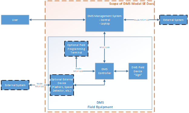 Figure 1: Reference Architecture for a DMS System with the scope of the DMS Model SE Documents ProcessThe target audience for this COU includes transportation agencies needing to procure relatively small-scale DMS systems by following a standardized systems engineering process without the need to hire a consultant. The COU will help an agency align their processes, operations and needs with the DMS System Engineering Model Documents, allowing the tailoring of the model document content. This process will lead to a set of user needs, requirements, verification plan and validation plan to support a successful procurement of a DMS system. A successful procurement results in a DMS system that not only meets the agency's needs but also provides a basis for ensuring that the procured system meets its advertised capabilities. The overall framework for the set of SE Model Documents is depicted in Figure 2 below. 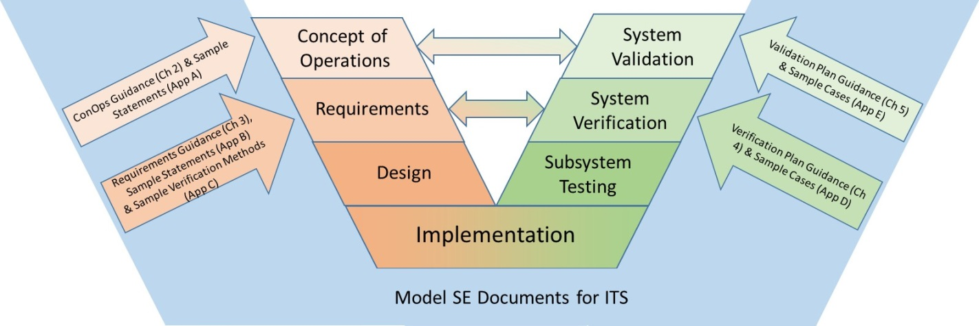 Figure 2: Concept of Use Process for SE Model Documents The DMS SE Model Documents begin with creating a Concept of Operations capturing typical representative use cases, and operational scenarios involving DMS systems. Use cases capture the system actors and activities in order to accomplish a specific purpose. An actor defines a role, which may be filled by a person, a group of people, or an external system. The actors form the foundation for the definition of the users of the system and are critical to the high-level use cases, operational scenarios and user needs. Operational scenarios provide examples in narrative form of how those users, activities and systems work together in actual practice. The ensuing analysis of the use cases, and operational scenarios lead directly to draft user needs (all embodied in the Concept of Operations), and the beginning of system validation cases validating the user needs documented in the Validation Plan. The user needs drive the definition of the requirements and the requirements verification methods (residing in the Requirements document) and a requirements Verification Plan. These have been previously reviewed and validated by operational DMS Subject Matter Experts (SMEs). The DMS SE Model Documents walk the user through the process of selecting and tailoring the pertinent use cases and operational scenarios in order to arrive at a set of user needs. Since the systems engineering process is being used, there is forward and backward traceability between the resulting user needs and the requirements. The verification plan and the requirements verification methods are directly traceable back to the requirements being verified. Correspondingly, the validation plan is directly traceable back to the user needs being validated. The DMS Model Systems Engineering Documents will provide an agency with a means to describe their existing and planned DMS system operations using substantive systems engineering products. In particular, the user will tailor the needs and requirements provided in the model. The process will provide meaningful systems engineering support for a DMS procurement with far less effort than developing systems engineering documents from scratch. The user will still be expected to understand their processes in applying a DMS system to solve their transportation management problems, but the model documents will provide guidance to the user to help them do so. Concept of OperationsThe first product of the application of the model documents will be a Concept of Operations for a DMS system. The Concept of Operations (ConOps) is written from the perspective of the system operator, and it establishes the activities of the user in solving the transportation management problem at hand, using DMS, as the basis for defining and defending requirements. The primary audience for the ConOps includes stakeholders who will participate in the operation of the system or be directly affected by it. The ConOps is responsible for capturing the stakeholder needs and expectations in a manner that is easily understandable to the stakeholder community, so that the stakeholder community can be confident that it properly models what they will do. The needs and expectations must be defined succinctly enough to determine what functions the proposed system must be capable of fulfilling. Stakeholders who may play a role in tailoring or reviewing the ConOps may include system operators, maintenance staff, system managers, administrators, decision-makers, elected officials, and other non-technical readers. Every element of the subsequent documents in the project, including the requirements, verification plan, designs, test procedures and processes and validation plan, must be able to be traced to statements of user need in the Concept of Operation. Ultimately, the ConOps describes how the agency will use the system, and in that manner could be considered a prototype for an operating policy and procedure. It is the basis for validating (via the Validation Plan) the system when delivered to ensure that the system is acceptable, with "acceptable" being defined as fulfilling all the user needs. The guidance for the Concept of Operations can be found in Chapter 2 of this guidance document. Requirements DocumentAfter the ConOps is defined, corresponding system requirements are captured in the DMS System Requirements Document. The requirements document targets technical staff, system users, system designers and vendors. The ConOps describes what the users will do, and the requirements define what the system must do. Each of the requirements listed in this document must be linked to a corresponding need described in the ConOps. Every need in the ConOps must be linked to one or more requirements in the Requirements Document. The forward and backward traceability between needs and requirements makes it possible to define needed requirements during procurement, and to defend requirements if they are challenged during procurement. The Requirements Document becomes the principal systems engineering document during the procurement process, providing the basis for selection, progress verification, (in some cases) payment, and system acceptance. Once the user has selected and defined their user needs, the SE Model Documents provide system requirements that are linked to those user needs. The guidance in the model documents will assist agency users in tailoring the model needs and requirements as needed, including any needed iteration between needs and requirements. During tailoring, you will need to iterate between needs and requirements to ensure that they remain traceable and consistent. Traceability ensures that each need is fully represented in the requirements, and each requirement is fully driven by needs. Consistency ensures that what the requirements require will satisfy the user needs to which they are traced. Once all the needs and requirements are tailored to the specific project, and checked for traceability and consistency, both the ConOps and the Requirements documents will be complete and correct. The DMS Systems Requirement Document does not define the design of the system, nor does it determine what technologies to use or how to implement them. This document sets the technical criteria that will be used to evaluate design and technology choices. It is the basis for verifying (via the Verification Plan) the system during design and when delivered to ensure that the system is acceptable, with "acceptable" being defined as fulfilling all the requirements. The recommended approach is to have an Acceptance Test of the procured system based on the system requirements. The guidance for the Requirements Document can be found in Chapter 3 of this guidance document. Verification PlanThis leads to the third document that the user will develop using the Model Documents, the DMS System Verification Plan. The Verification Plan is responsible for defining the verification testing that will demonstrate fulfillment of requirements. The target audience for this document is the same as for the Requirements document. Generally, the implementing contractor will be responsible to fulfill the requirements. The Verification Plan describes the general verification effort including verification cases with corresponding requirements being fulfilled, including the method by which that determination will be made. It is critical that all requirements are verified within the scope of the Verification Plan. This is best done by tracing each requirement into a verification case and eventually into appropriate steps in the verification procedures. The Model Documents provide a direct mapping of verification cases to the requirements. The user simply needs to extract and tailor the corresponding verification cases related to the chosen set of requirements. The Verification Plan does not describe detailed procedures for testing the DMS System. It is typical that the system developer/supplier/vendor will develop the verification test procedures that will map to the verification plan as part of the procurement process. The specific steps of a verification test procedure require a knowledge of the specific software and hardware technology that will be implemented. The guidance for the Verification Plan can be found in Chapter 4 of this guidance document. Validation PlanThe fourth document that the user will develop using the Model Documents is the DMS System Validation Plan. The Validation Plan is responsible for defining the validation testing that will demonstrate that the system meets the user needs. The target audience for this document is the same as for the Concept of Operations (ConOps) document. Generally, the implementing contractor will not be responsible for validation. The Validation Plan describes the general validation effort including validation cases with corresponding user needs being fulfilled. The Model Documents provide a direct mapping of validation cases to the user needs categories. The user simply needs to extract and tailor the corresponding validation cases related to the chosen set of user needs. The Validation Plan does not describe detailed procedures for validation testing of the DMS System. Typically, once the DMS System has been accepted, the users of the system will validate if the system meets their user needs according to the Validation Plan and subsequent validation procedures. The guidance for the Validation Plan can be found in Chapter 5 of this guidance document. ProcurementFinally, the guidance within the model documents includes a general discussion of procurement approaches, and how the products of the systems engineering process support various procurement processes. The guidance for procurement can be found in Chapter 6 of this guidance document. Assembling Your DocumentsThe finished product of your efforts will be several systems engineering documents. In order to successfully prepare these documents, you will need to take the following steps:
SummaryIn summary, the DMS System Model Documents will provide documentation templates that will guide the user through the selection and insertion of applicable user needs, requirements, verification cases and validation cases that are consistent with each other. The Model Documents will provide guidance to the user on selecting operational DMS system capabilities that fit within the use cases and operational scenarios. The focus of this guidance is to develop documents that will enable the agency to successfully procure a DMS system that is currently available in the product market. It should be stressed that the responsibility for preparation of these DMS Systems Engineering documents rests entirely with the procuring agency. |
|
United States Department of Transportation - Federal Highway Administration |
||