Model Systems Engineering Documents for Dynamic Message Sign (DMS) Systems
Appendix F: Standardized Communications Protocol Stack Interface Diagrams
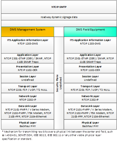 Figure 9. Communications Protocol Standards for the NTCIP-SMTP Triple of DMS Management System ⇒ roadway dynamic signage data ⇒ DMS Field Equipment based on the DMS System Project Architecture Diagram
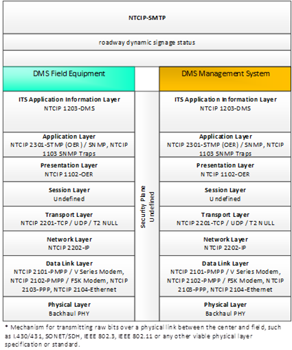 Figure 10. Communications
Protocol Standards for the NTCIP-SMTP Triple of DMS Field Equipment ⇒ roadway dynamic signage status ⇒ DMS Management System based on the DMS System Project Architecture Diagram
Figure 10. Communications
Protocol Standards for the NTCIP-SMTP Triple of DMS Field Equipment ⇒ roadway dynamic signage status ⇒ DMS Management System based on the DMS System Project Architecture Diagram
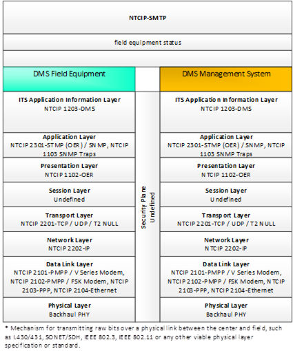 Figure 11. Communications Protocol Standards for the NTCIP-SMTP Triple of DMS Field Equipment ⇒ field equipment status ⇒ DMS Management System based on the DMS
System Project Architecture Diagram
Figure 11. Communications Protocol Standards for the NTCIP-SMTP Triple of DMS Field Equipment ⇒ field equipment status ⇒ DMS Management System based on the DMS
System Project Architecture Diagram
 Figure 12. Communications
Protocol Standards for the NTCIP-SMTP Triple of DMS Management System ⇒ field equipment configuration settings ⇒ DMS Field Equipment based on the DMS System Project Architecture Diagram
Figure 12. Communications
Protocol Standards for the NTCIP-SMTP Triple of DMS Management System ⇒ field equipment configuration settings ⇒ DMS Field Equipment based on the DMS System Project Architecture Diagram
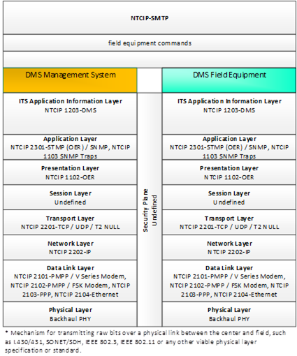 Figure 13. Communications Protocol Standards for the NTCIP-SMTP Triple of DMS Management System ⇒ field equipment commands ⇒ DMS Field Equipment based on the DMS System Project Architecture Diagram
 Figure 14. Communications Protocol Standards for the NTCIP-SMTP Triple of DMS Management System ⇒ field equipment software install/upgrade ⇒ DMS Field Equipment based on the DMS System Project Architecture Diagram
 Figure 15. Communications
Protocol Standards for the NTCIP-SMTP Triple of Field Support Computer ⇒ roadway dynamic signage data ⇒ DMS Field Equipment based on the DMS System Project Architecture Diagram
Figure 15. Communications
Protocol Standards for the NTCIP-SMTP Triple of Field Support Computer ⇒ roadway dynamic signage data ⇒ DMS Field Equipment based on the DMS System Project Architecture Diagram
 Figure 16. Communications Protocol Standards for the NTCIP-SMTP Triple of DMS Field Equipment ⇒ roadway dynamic signage status ⇒ Field Support Computer based on the DMS System Project Architecture Diagram
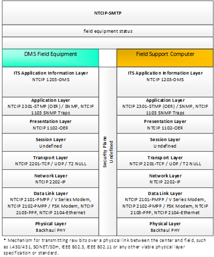 Figure 17. Communications
Protocol Standards for the NTCIP-SMTP Triple of DMS Field Equipment ⇒ field equipment status ⇒ Field Support Computer based on the DMS System Project Architecture Diagram
Figure 17. Communications
Protocol Standards for the NTCIP-SMTP Triple of DMS Field Equipment ⇒ field equipment status ⇒ Field Support Computer based on the DMS System Project Architecture Diagram
 Figure 18. Communications Protocol Standards for the NTCIP-SMTP Triple of Field Support Computer ⇒ field equipment configuration settings ⇒ DMS Field Equipment based on the DMS System Project Architecture Diagram
 Figure 19. Communications Protocol Standards for the NTCIP-SMTP Triple of Field Support Computer ⇒ field equipment commands ⇒ DMS Field Equipment based on the DMS
System Project Architecture Diagram
Figure 19. Communications Protocol Standards for the NTCIP-SMTP Triple of Field Support Computer ⇒ field equipment commands ⇒ DMS Field Equipment based on the DMS
System Project Architecture Diagram
 Figure 20. Communications Protocol Standards for the NTCIP-SMTP Triple of Field Support Computer ⇒ field equipment software install/upgrade ⇒ DMS Field Equipment based on the DMS System Project Architecture Diagram
 Figure 21. Communications Protocol Standards for the NTCIP-SNMP Triple of DMS Management System ⇒ roadway dynamic signage data ⇒ DMS Field Equipment based on the DMS System Project Architecture Diagram
 Figure 22. Communications Protocol Standards for the NTCIP-SNMP Triple of DMS Field Equipment ⇒ roadway dynamic signage status ⇒ DMS Management System based on the DMS System Project Architecture Diagram
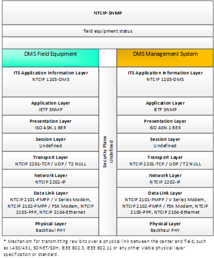 Figure 23. Communications
Protocol Standards for the NTCIP-SMTP Triple of DMS Field Equipment ⇒ field equipment status ⇒ DMS Management System based on the DMS System Project Architecture Diagram
Figure 23. Communications
Protocol Standards for the NTCIP-SMTP Triple of DMS Field Equipment ⇒ field equipment status ⇒ DMS Management System based on the DMS System Project Architecture Diagram
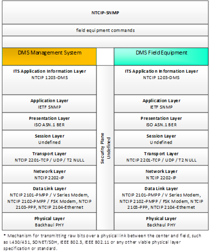 Figure 24. Communications Protocol Standards for the NTCIP-SNMP Triple of DMS Management System ⇒ field equipment commands ⇒ DMS Field Equipment based on the DMS
System Project Architecture Diagram
Figure 24. Communications Protocol Standards for the NTCIP-SNMP Triple of DMS Management System ⇒ field equipment commands ⇒ DMS Field Equipment based on the DMS
System Project Architecture Diagram
 Figure 25. Communications Protocol Standards for the NTCIP-SNMP Triple of DMS Management System ⇒ field equipment configuration settings ⇒ DMS Field Equipment based on the DMS System Project Architecture Diagram
 Figure 26. Communications Protocol Standards for the NTCIP-SNMP Triple of DMS Management System ⇒ field equipment software install/upgrade ⇒ DMS Field Equipment based on the DMS System Project Architecture Diagram
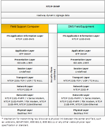 Figure 27. Communications Protocol Standards for the NTCIP-SNMP Triple of Field Support Computer ⇒ roadway dynamic signage data ⇒ DMS Field Equipment based on the DMS System Project Architecture Diagram
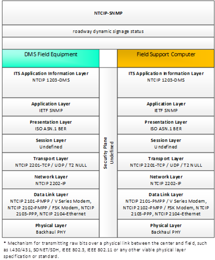 Figure 28. Communications Protocol Standards for the NTCIP-SNMP Triple of DMS Field Equipment ⇒ roadway dynamic signage status ⇒ Field Support Computer based on the DMS System Project Architecture Diagram
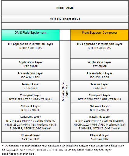 Figure 29. Communications Protocol Standards for the NTCIP-SNMP Triple of DMS Field Equipment ⇒ field equipment status ⇒ Field Support Computer based on the DMS
System Project Architecture Diagram
Figure 29. Communications Protocol Standards for the NTCIP-SNMP Triple of DMS Field Equipment ⇒ field equipment status ⇒ Field Support Computer based on the DMS
System Project Architecture Diagram
 Figure 30. Communications Protocol Standards for the NTCIP-SNMP Triple of Field Support Computer ⇒ field equipment commands ⇒ DMS Field Equipment based on the DMS
System Project Architecture Diagram
Figure 30. Communications Protocol Standards for the NTCIP-SNMP Triple of Field Support Computer ⇒ field equipment commands ⇒ DMS Field Equipment based on the DMS
System Project Architecture Diagram
 Figure 31. Communications Protocol Standards for the NTCIP-SNMP Triple of Field Support Computer ⇒ field equipment configuration settings ⇒ DMS Field Equipment based on the DMS System Project Architecture Diagram
 Figure 32. Communications Protocol Standards for the NTCIP-SNMP Triple of Field Support Computer ⇒ field equipment software install/upgrade ⇒ DMS Field Equipment based on the DMS System Project Architecture Diagram
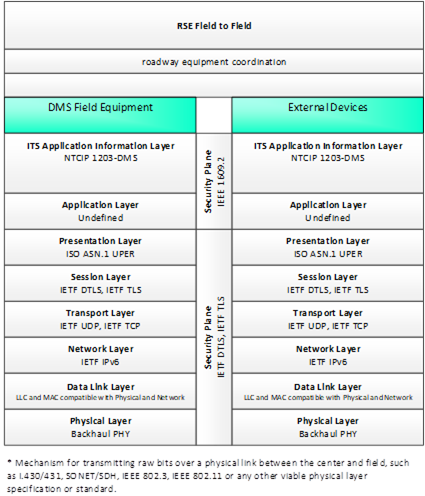 Figure 33. Communications Protocol Standards for the RSE Field to Field Triple of DMS Field Equipment ⇒ roadway equipment coordination ⇒ External Devices based on the DMS System Project Architecture Diagram
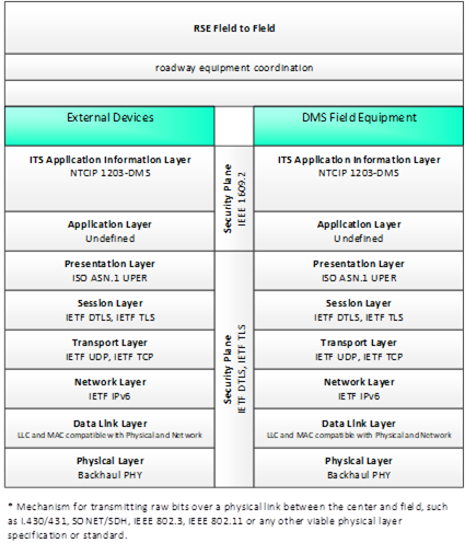 Figure 34. Communications Protocol Standards for the RSE Field to Field Triple of External Devices ⇒ roadway equipment coordination ⇒ DMS Field Equipment based on the DMS System Project Architecture Diagram
|