Use of Freeway Shoulders for Travel — Guide for Planning, Evaluating, and Designing Part-Time Shoulder Use as a Traffic Management Strategy
Chapter 7. Design Considerations
Part-time shoulder use typically utilizes an existing shoulder; therefore, the design of a part-time shoulder use implementation project is typically less involved than the design of a full-time added lane. However, the same elements of roadway design—geometry, pavement, drainage, and signing and pavement marking—are applicable to both full-time lanes and lanes designated for part-time shoulder use and require some level of attention prior to implementation. Preexisting pavement and drainage should be assessed before part-time shoulder use is implemented, and improvements or modifications may be necessary. Special signing and pavement markings are necessary for part-time shoulder use, and dynamic signs are often used.
Designing for operations is “the collaborative and systematic consideration of management and operations during transportation project design and development” (36). In the context of part-time shoulder use, a designing for operations process incorporates design features needed for part-time shoulder use—full depth pavement, sufficiently wide shoulders and lateral offsets, space for turnouts, and so forth—into the design of a facility where there is a reasonable likelihood that part-time shoulder use would someday be implemented. Part-time shoulder use is typically implemented on older freeways in constrained environments, so the design project in which a designing for operations process is used may be a reconstruction project rather than a new facility.
This chapter presents design considerations for part-time shoulder use in the context of existing design practices for facilities without part-time shoulder use and the experiences of states that have implemented part-time shoulder use. There is little quantitative research on design elements of part-time shoulder use, and much will be learned in this area in the coming years as new facilities are built and existing facilities age.
Geometric Design
From a geometric design perspective, freeway part-time shoulder use can be subdivided into three types of segments:
- Beginning and end segments
- Basic freeway segments
- Ramp-freeway junction segments
This section presents geometric design considerations for each of these segment types, as well as design considerations for arterials with part-time shoulder use and emergency turnout areas.
Part-time shoulder use may introduce design elements that are below the minimum criteria specified in AASHTO’s A Policy on Geometric Design of Highways and Streets (Green Book)(37) and design exceptions may be required. If the facility is an Interstate Highway, design elements in AASHTO’s A Policy on Design Standards — Interstate System(38) also apply. The Basic Freeway Segment section below presents design criteria that part-time shoulder use may affect and require design exceptions. The process for obtaining a design exception is covered in CHAPTER 9.
Beginning and End Segments
Logical termini should be established during project scoping and preliminary design consistent with National Environmental Policy Act (NEPA) guidance. Part-time shoulder use can begin and end along basic segments or at ramps. If the beginning or end of static or dynamic part-time shoulder use is along a basic freeway segment, then it is desirable for it to be located such that it is highly visible and comprehended by approaching drivers. Horizontal curves, crest vertical curves, and overpasses may limit a driver’s visibility of a downstream roadway, and dropping any type of lane—including part-time shoulder use—within or immediately beyond these features, should be avoided if possible. Likewise, dropping any type of lane in or immediately beyond an area with extensive, complex signing or other features contributing to high driver workload should be avoided if possible.
There are fewer considerations associated with adding a general purpose lane in comparison to dropping a general purpose lane because it requires no action on the part of the driver. However, starting part-time shoulder use requires a series of signs to indicate use restrictions and the point at which use of the shoulder becomes allowable. Therefore, the desirable locations for lane drops described above are also desirable locations to start part-time shoulder use.
Beginning of Part-time Shoulder Use
Part-time shoulder use added along basic freeway segments should have pavement markings that guide drivers from the adjacent general purpose lane to the shoulder, but also maintain continuity of the general purpose lane. Typically, a diagonal solid edge line provides a transition from the edge of the general purpose lane to the edge of the shoulder, and a dotted edge line connects the edge line adjacent to the general purpose lane before and after the transition to the part-time shoulder use. Striping for the beginning of part-time shoulder use is shown below in Figure 24.
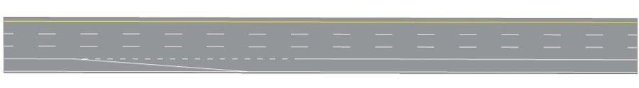
Figure 24. Illustration. Typical part-time shoulder use add.
(Source: Kittelson & Associates, Inc.)
Part-time shoulder use may also begin as an add “lane” from an on-ramp, with pavement markings supporting both ramp-to-general purpose lane and ramp-to-shoulder movements. At the end of the speed-change lane for a parallel style ramp, drivers from the on-ramp merge into the general purpose lane when the shoulder is closed and continue straight into the shoulder when it is open. This method of adding is most desirable at high-volume ramp locations where the merge of traffic from the on-ramp onto the freeway creates a bottleneck on the freeway. It is least desirable at locations where it is undesirable for a significant portion of on-ramp traffic to use the shoulder, such when the shoulder is restricted to high-occupancy vehicle (HOV) traffic or an on-ramp with a high percentage of truck traffic.
End of Part-time Shoulder Use
The end of part-time shoulder use along a basic freeway segment is designed similarly to the beginning of part-time shoulder use. A solid edge line is typically used to transition traffic from the shoulder back to the adjacent general purpose lane, shown in Figure 25.
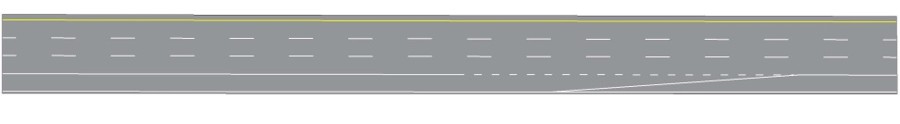
Figure 25. Illustration. Typical part-time shoulder use drop.
(Source: Kittelson & Associates, Inc.)
In general, basic freeway lanes should not be trapped onto exit ramps because this is unexpected to drivers, and the same applies to part-time shoulder use. However, at large system interchanges, it is more common to drop lanes onto ramps because a large percentage of the traffic is exiting. If exit ramps and the part-time shoulder use are on the same side of the freeway, dropping the shoulder use onto the exiting ramp may be reasonable depending on traffic patterns. Other strategies at system interchanges include ending the part-time shoulder use at the same location where a general purpose lane is added (because general purpose lanes are often added in advance of system interchanges) and carrying the part-time lane through the system interchange if the exiting and entering ramps have one or two lanes are designed in a manner that will not create conflicts (see ramp-freeway junction section of this chapter). Carrying part-time shoulder use through system interchanges is complex due to conflicts with exiting and entering traffic and the role part-time shoulder use serves on the freeway network, and should be done with caution. System interchanges often change volume (to a significant degree) or number of basic lanes on a facility, and there is often a not a need for part-time shoulder use both upstream and downstream of a system interchange.
At major forks, part-time shoulder use can be carried onto one of the forks. This is desirable if the ramps downstream of the fork have more lanes than the freeway approaching the fork. US 2 in Washington State and SR 29 in New Jersey both have part-time shoulder use in one direction that terminate this way. SR 29, for example, has three general purpose lanes upstream of the fork and two two-lane ramps downstream of the fork. Figure 26 shows an example of part-time shoulder use used to remove a bottleneck upstream of a major fork. The part-time shoulder use in Figure 26 is on the right side and provides the second lane to the right side fork, terminating into a general purpose lane on the ramp.
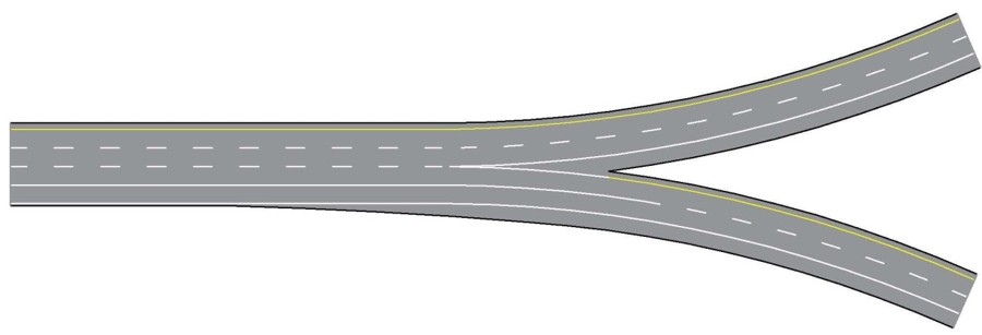
Figure 26: Illustration. Part-time shoulder use approaching major fork.
(Source: Kittelson & Associates, Inc.)
Shoulder Use Between Interchanges Only
Georgia and Hawaii use static part-time shoulder use between (but not through) adjacent interchanges to effectively create part-time auxiliary lanes and mitigate the effects of closely- spaced entrance and exit ramps. In this case, the shoulder is not functioning as a basic freeway lane, and a drop onto a service interchange is necessary and inherent in the design.
Basic Freeway Segments
Controlling design criteria and their minimum values from the AASHTO Green Book(37) and AASHTO’s A Policy on Design Standards — Interstate System are presented in Table 11.(38) When the Green Book has different values for different types of facilities, only the freeway values are presented because part-time shoulder use is typically implemented on freeways. Minimum values from both AASHTO publications are the same for many of the criteria, and are only noted separately if they differ. In one or both documents, some minimum criteria are required (“shall”) as opposed to desired (“should”). A design exception is needed if required minimum values are not met (on roadways on the National Highway System). States should work with their Federal Highway Administration (FHWA) Division Office when considering design exceptions on the National Highway System.
Existing design features often dictate part-time shoulder use dimensions. However, as discussed in 0, higher quality geometry meeting or exceeding AASHTO criteria, when possible, generally leads to higher utilization and capacity of the shoulder, compared to more constrained geometry.
Table 11. Controlling criteria, minimum AASHTO values, and relationship to part-time shoulder use.
|
Controlling Criteria
|
Minimum AASHTO Values(37, 38, 39)
|
Affected by Part-time shoulder use
|
|
Design Speed
|
Chosen by agency. Shall be at least 50 mph in urban areas, should be 70 mph in rural areas, may be 50-60 mph in mountainous areas
|
No, unless agency choses to reduce it
|
|
Lane Width
|
Shall be 12 feet
|
Possibly
|
|
Shoulder Width (values for paved width presented)
|
4-lane freeways — Right shoulder shall be 10+, left shoulder shall be 4+ feet
6+-lane freeways — both shoulders should be 10+ feet
Truck traffic exceeds 250 DDHV — 12+ foot shoulders on both sides should be considered
|
Always
|
|
Bridge Width
|
Less than 200 feet long — Shall equal full paved width of approach roadway
200+ feet long, Green Book — provide approach shoulder widths and median barrier if single structure.
200+ feet long, Interstate Standards — offsets to parapet, rail, or barrier shall be 4+ feet from travel lane
|
Likely
|
|
Horizontal Alignment
|
Varies based on design speed and maximum superelevation (see Green Book Table 3-7)
|
Possible
|
|
Superelevation
|
Maximum of 6 to 12 %, should consider maximum of 6 to 8 % where snow and ice are a concern
|
Possible
|
|
Vertical alignment
|
Varies based on several elements (see Green Book Figure 3-43 for sag curves and 3-44 for crest curves)
|
Never
|
|
Grade
|
Varies 3 to 6% by type of terrain and design speed (See Green Book Table 8-1)
|
Never
|
|
Stopping Sight Distance
|
Varies based on design speed and grade (See Green Book Table 3-1 and 3-2)
|
Possibly
|
|
Cross slope
|
Green Book — 1.5 to 2 %
Interstate Standards — Shall be 1.5% minimum, desirably 2%, may be 2.5% in areas of intense rainfall. Shoulder slopes should be in range of 2 to 6 %
|
Possibly
|
|
Vertical clearance
|
Green Book — Shall be 16+ feet over lanes and shoulders in rural areas and at least a single freeway route through highly developed urban areas, shall be 14+ feet on other highly developed urban freeway routes
Interstate Standards — Shall be 16+ feet over lanes and shoulders in rural areas and at least a single Interstate through urban areas, shall be 14+ feet on other urban Interstate routes
|
Possibly
|
|
Lateral offset to obstruction
|
Green Book — refers to AASHTO Roadside Design Guide, which specifies a minimum width of 1.5 feet.
Interstate Standards — Shall be consistent with shoulder width requirements
|
Likely
|
|
Structural capacity
|
Green Book — Minimum HL 93 design loading structural capacity
Interstate Standards — New bridges — HS 20, existing bridges — assess operating rating capacity for additional 20 year service life
|
Unlikely
|
Discussion of how part-time shoulder use may affect these minimum values is presented in the following sections. Minnesota has developed state standards for bus-on-shoulder (BOS); these standards have been used by other states with BOS operation and they are presented in the following sections as well.(40)
Design Speed
The selected design speed influences several geometric design criteria. The implementation of part-time shoulder use does not inherently change the design speed of the overall freeway facility. A lane designated for part-time shoulder use may have dimensions that are slightly below the minimum values set by the design speed (some of which may require a design exception), and the design speed could be reduced. This is rare and would occur in a situation such as a road with existing horizontal curves at the minimum radius and the shoulder having a radius that is 10 to 12 feet less than the minimum.
Lanes designated for static and dynamic part-time shoulder use typically have the same speed limit as the rest of the facility on which they are located. If the shoulder is assigned a lower speed limit, or the shoulder is only open to traffic when facility operating speeds fall below posted speeds, then adjustments to selected design values may be acceptable. A variable speed limit could also be used to maintain the existing speed limit when the shoulder is closed and to lower the speed limit when the shoulder lane is open. Minnesota and some other states limit the speed of buses travelling in BOS lanes to 35 mph, and MnDOT has adopted 35 mph as the design speed of BOS lanes.
Lane Width
A shoulder width of 12 or more feet is generally preferred for part-time shoulder use. A 12-foot shoulder creates a “shoulder lane” that is the same width as a typical general purpose lane. This dimension refers to the distance from the general purpose lane edge line to the edge of pavement. A second edge line is sometimes added near the edge of pavement to guide drivers on the shoulder and increase the delineation of the edge of pavement; however, pavement on both sides of a second edge line constitutes part of the shoulder. Research summarized in Chapter 3 of this guide has shown drivers are more likely to use 12-foot shoulders than narrower shoulders.
Shoulders less than 12 feet wide may be adequate for shoulder use depending upon the type of vehicles using the shoulder when it is open and depending on the availability of lateral offset to obstructions beyond the edge of pavement. If trucks are prohibited from using the shoulder, then shoulder widths as narrow as 10 feet may be adequate. Shoulders less than 10 feet wide are not recommended for part-time shoulder use.
A 10-foot shoulder may be inadequate if the lateral offset to obstructions is less than 1.5 feet or a high volume of larger vehicles, such as buses, is anticipated. Opening the shoulder only when congestion is present and reducing the speed limit when the shoulder is open are likely to improve the safety of a narrow shoulder during part-time shoulder use.
Minnesota standards for BOS specify a minimum “shoulder lane” width of 10.0 feet and a minimum total shoulder width of 12.0 feet (implying a two-foot paved area between the second edge lane and edge of pavement). A lane width of 12.0 feet is required “in areas of new construction or reconstruction”. Massachusetts design criteria specify a width of 11 feet for “shoulder lanes” and also require a one- to two-foot paved area beyond the travelled portion of the shoulder (implying a minimum total shoulder width of 12-13 feet).(41)
Shoulder Width
Designating the paved freeway shoulder for part-time travel use will typically require a design exception since there will typically be little or no untraveled shoulder beyond the portion of the shoulder used for part-time travel, and this will not meet the minimum width requirements.
Bridge Width
Many bridges have narrower shoulders than the approach roadways. The minimum width of a shoulder on a bridge that should be used as a travel lane is 11.5 feet. This dimension enables vehicles to remain 1.5 feet from the bridge rail and still have 10 feet of shoulder on which to maneuver. It is not necessary for the shoulder to be the same width on a bridge as on the approaching roadway, however, it does need to be 11.5 or more feet wide. Design exceptions may be needed for the narrow lane width.
Minnesota standards for BOS lanes specify a minimum bridge [shoulder] width of 11.5 feet and a desirable bridge [shoulder] width of 12.0 feet. A width of 12.0 feet is required “in areas of new construction or reconstruction”. These standards effectively maintain a 10.0 foot shoulder lane and a 1.5-foot paved lateral offset to the bridge rail, which is consistent with MnDOT’s BOS design standards.
Horizontal Alignment
A shoulder on the inside of a horizontal curve will have a smaller radius than the adjacent general purpose lane. However, the difference in radii is small, and it is unlikely to result in a radius below AASHTO minimum values. If AASHTO minimum values are not met, then a design exception could be obtained. In practice, states have not reported issues with horizontal curvature when implementing part-time shoulder use.
Superelevation
Through horizontal curves, the superelevation of shoulders may differ from the superelevation of adjacent general purpose lanes to facilitate drainage. In some cases, there may be a cross slope break on the shoulder, or the entire shoulder may be superelevated in the opposite direction of general purpose lanes to direct water to inlets. In practice, states have reported issues with this on left shoulders with concrete median barriers. Roadways designated for part-time shoulder use should not have superelevation breaks and shoulders on these roads should generally have the same superelevation as adjacent general purpose lanes. Small superelevation differences of 2% or less may be acceptable, with the break occurring on the edge line between the shoulder and general purpose lanes.
Stopping Sight Distance
On the inside of horizontal curves, traffic using the shoulder will be closer to guardrails or barriers if they are present. This may reduce sight distance, and it may reduce it below AASHTO minimum design values. If this occurs, it may be appropriate to relocate the barrier causing the sight distance obstruction or obtain a design exception. Minnesota addresses this issue by basing SSD of BOS lanes on 35 mph, the maximum speed at which buses are permitted to operate.
Cross Slope
Cross slopes on shoulders are sometimes greater than adjacent general purpose lanes to facilitate drainage, creating two potential issues. First, the algebraic difference between the shoulder and the adjacent travel lane may be too abrupt to safely accommodate vehicles transitioning between them. If it exceeds seven to eight percent, then an agency should consider rounding the grade break or prohibiting lane changes to and from the shoulder in the affected area.(42) Prohibiting movement between the shoulder and general purpose lanes would be most effective for BOS operation, with a small number of professional drivers needing to obey the restriction. Second, regardless of algebraic difference, if shoulder cross slopes are greater than the travel lane values in Table 11, then it is necessary to reduce shoulder cross slope by adding pavement on top of existing pavement to modify the cross slope or obtaining a design exception. If existing or modified cross slopes and the current drainage system create ponding on the shoulder and there is no feasible means of addressing it, then the freeway is a good candidate for dynamic part-time shoulder use that can be closed during and after heavy rainfall or snowmelt.
Vertical Clearance
As shown in Table 11, AASHTO vertical clearance requirements are the same for travel lanes and shoulders. However, many bridges have lower clearances over shoulders because they pre- date current AASHTO policies or previously obtained design exceptions. In these cases, it is still necessary to ensure there is adequate vertical clearance for vehicles using the shoulder.
Part-time shoulder use generally prohibits trucks, which effectively eliminates the tallest vehicles from using the shoulder. During the preliminary engineering stage, a state DOT’s permitting group can typically provide information on the vertical clearance of bridges because they maintain an inventory for the purpose of providing permits for oversize/overweight trucks. Prior to implementing part-time shoulder use, agencies typically field measure the height of bridges along a route, and any substandard vertical clearances dictate additional vehicle restrictions beyond trucks.
Lateral Offset to Obstruction
Lateral offset to obstruction, called horizontal clearance in previous editions of the Green Book, is the distance from the edge of the traveled way to the nearest physical obstruction such as a median barrier, guard rail, bridge support, or bridge rail. The minimum width of 1.5 feet is automatically met on a full-standard freeway because minimum shoulder widths are greater than 1.5 feet. However, the lateral offset between the edge of a shoulder and an obstruction may be less than 1.5 feet. In this case, it is necessary to move the obstruction or obtain a design exception.
In practice, states have relocated guardrails and other obstructions (sign and lighting structures), and obtained design exceptions for segments adjacent to bridge rails/barriers and abutments, or other concrete barrier, where less than 1.5 feet or lateral offset is available.
Other Criteria
Vertical alignment, grade, and structural capacity are unlikely to be affected by part-time shoulder use.
Ramp Freeway Junctions
Ramp-freeway junctions are the locations at which ramps merge with and diverge from the mainline freeway. The types of ramps and their specific geometric characteristics will influence the details of part-time shoulder use design in these areas. This, in turn, influences the overall quality of operation, including the capacities of ramps and the shoulder lane.
One-lane Ramps
Part-time shoulder use is generally compatible with one-lane ramps. Typical designs for the two basic types of ramp-freeway junctions—parallel and taper—are shown in the sections below.
Parallel Ramps: With parallel entrances and exits, entering and exiting traffic drives on a short speed change lane beside the outermost freeway lane (for right-side ramps) for several hundred feet before an exit gore or after an entrance gore. The speed change lane is essentially a striped portion of the shoulder.
When part-time shoulder use is added to a facility with parallel ramps and open to traffic, the shoulder lane can tie into the existing speed change lanes. This effectively converts the parallel ramp into a taper ramp during the hours the facility is open. Figure 27 shows the path of ramp traffic on a parallel-style on-ramp. If the shoulder lane is closed, ramp traffic uses speed change lane and then maneuvers to the adjacent general purpose lane, as shown with shading in Figure 27. If the shoulder lane is open, the speed change lane is part of the shoulder lane and on-ramp traffic no longer has an unimpeded path onto it. The ramp is effectively converted to a taper- style. At the end of speed change lane, on-ramp drivers may maneuver into the adjacent general purpose lane or continue straight into the shoulder lane. Similar changes occur at parallel-style off-ramps, as shown in Figure 28.
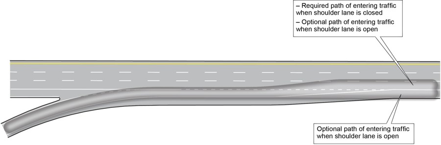
Figure 27. Illustration. Path of parallel-style on-ramp traffic with part-time shoulder use.
(Source: Kittelson & Associates, Inc.)
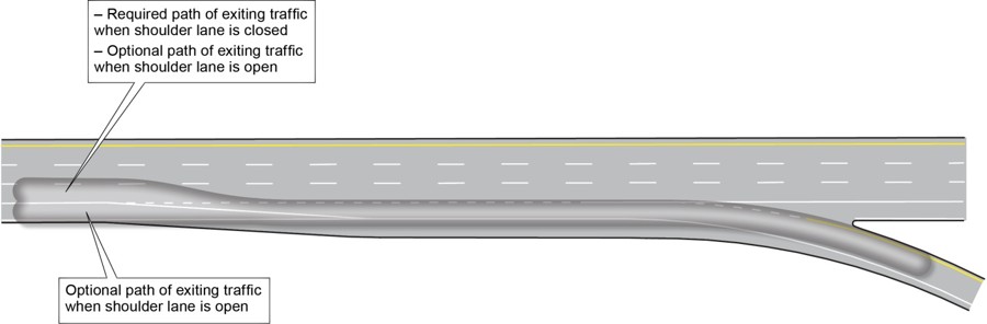
Figure 28. Illustration. Path of parallel-style off-ramp traffic with part-time shoulder use.
(Source: Kittelson & Associates, Inc.)
The operational effects of a part-time conversion of a parallel-style ramp to a taper-style ramp vary based on the geometric characteristics of the ramp and gore area. For example, a gore with a relatively large convergence angle will result in a short maneuver area at the end of an on-ramp when the shoulder lane is open, likely reducing capacity of the on-ramp and shoulder lane. A gore with a relatively small convergence angle will result in a longer maneuver area and have lesser impacts on capacity. This is shown in Figure 29 and Figure 30.
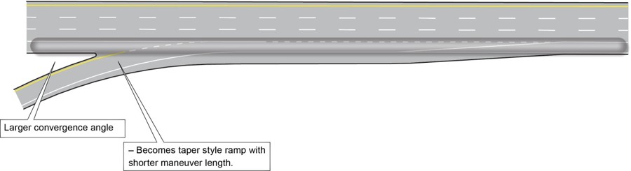
Figure 29. Illustration. Parallel-style ramp with large convergence angle. Shoulder lane shaded.
(Source: Kittelson & Associates, Inc.)
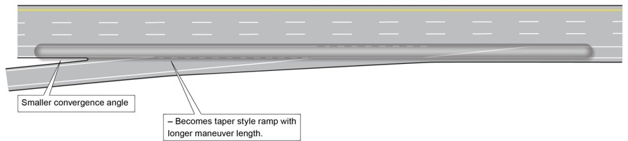
Figure 30. Illustration. Parallel-style ramp with small convergence angle. Shoulder lane shaded.
(Source: Kittelson & Associates, Inc.)
Taper Ramps: Taper-style ramps do not have speed change lanes, and ramp traffic effectively “crosses” the shoulder in a single maneuver. If a shoulder was opened to traffic and this configuration was kept in place, it would result in a conflict between shoulder lane traffic and ramp traffic, as shown for an off-ramp in Figure 31.
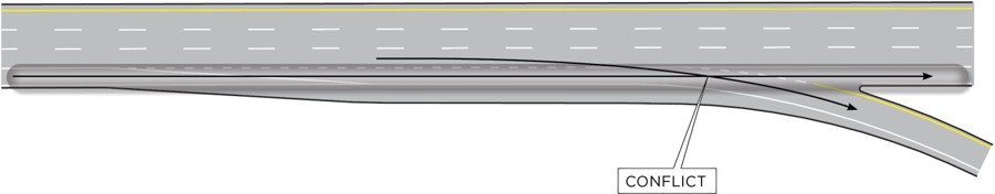
Figure 31. Illustration. Conflict between ramp and shoulder traffic with taper-style ramp. Shoulder lane shaded.
(Source: Kittelson & Associates, Inc.)
To remove the conflict, the ramp should be converted into a parallel-style ramp with a speed- change lane. For an off-ramp, exiting traffic will maneuver onto the combined speed-change lane/shoulder lane prior to the exit as shown in Figure 32. Implementing shoulder use will already require that the shoulder be physically capable of carrying traffic, so the addition of the speed-change lane will typically require only pavement marking changes.
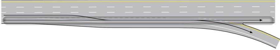
Figure 32. Illustration. Conversion of taper-style ramp to parallel-style ramp to remove conflict between ramp and shoulder traffic. Shoulder lane shaded.
(Source: Kittelson & Associates, Inc.)
Two-lane Ramps
Design of shoulder lanes through two-lane ramps is more complex than one-lane ramps, and some types of two-lane ramps are not compatible with shoulder use without major modifications.
Parallel ramps: A parallel-style two-lane on-ramp has two speed-change lanes downstream of the entry gore that receive ramp traffic. Typically, they are different lengths, with the outer lane terminating before the inner lane. With shoulder use, the inner speed change lane will become part of the shoulder lane, as shown in Figure 33. When the shoulder lane is open, this will effectively create a taper-style two-lane on-ramp with an inside merge. Inside merges reduce ramp capacity and should be used with caution because they may be unexpected to drivers. They are most appropriate to use at locations where ramp and freeway drivers have good visibility to the gore and adequate time to prepare for the merge.
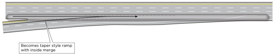
Figure 33. Illustration. Creation of inside merge with parallel-style two-lane on-ramp. Shoulder lane shaded.
(Source: Kittelson & Associates, Inc.)
Design of a shoulder lane through a parallel-style off-ramp is similar to the design of the on- ramp shown in Figure 35. There are generally no issues associated with the loss of the inside speed-change lane when the shoulder lane is open and the creation of an “inside diverge”.
Taper ramps: A taper-style two-lane on-ramp typically has an inside merge, and shoulder use will create a conflict between shoulder lane traffic and inside lane ramp traffic as shown in Figure 34. A similar conflict exists with taper-style two-lane off-ramps. Removal of this conflict is more complex than with single-lane ramp, and would typically involve adding a second speed- change lane downstream of the entry gore. In these cases, consideration should also be given to terminating the shoulder lane project upstream or downstream of the two-lane ramp, reducing the ramp to a single lane, or implementing junction control to vary the lane configuration in response to traffic conditions.
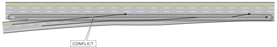
Figure 34. Illustration. Conflict between ramp and shoulder traffic with two-lane taper- style ramp with inside merge. Shoulder lane shaded.
(Source: Kittelson & Associates, Inc.)
Turnout Placement/Design
Based on experience in Massachusetts, Virginia, and the UK, refuge spaces for disabled vehicles should be located approximately every half-mile along a facility with static or dynamic shoulder use.(2) At this distance, a vehicle in the process of breaking down is generally able to reach the refuge.
Sometimes, gore areas or ramp shoulders at entrances and exits provide a refuge space large enough to store a vehicle. When this is not the case or when ramp spacing exceeds a half-mile, emergency turnouts should be constructed. Turnouts should be long enough and wide enough that a vehicle with poor control and in the process of breaking down can enter it and be out of the shoulder lane. They should also be long enough to enable a tow truck to park and load a broken down vehicle. Turnouts should be a minimum of 16 feet wide to provide separation between a broken down vehicle and moving traffic in the shoulder, and additional width is desirable. Massachusetts uses turnouts that are 16 feet wide, 110 feet long, and have 300-foot tapers.(41) Virginia’s turnouts are approximately the same width and have approximately the same taper length, but are several times longer than 110 feet. Virginia does not limit turnout lengths to a maximum distance, and paves existing flat areas along the roadside, if present, to increase turnout length. The UK uses shorter tapers, approximately 80 feet for the entrance and 150 feet for the exit.(2)
Turnouts should be used exclusively as refuge areas for disabled vehicles, and not for other purposes such as overnight truck park. States have not reported issues with this, but if they occur they should be addressed quickly with signing and law enforcement.
If turnouts cannot be constructed, such as on bridge or other constrained areas, then part-time shoulder use can still be implemented, but there is a greater probability the shoulder will be blocked by disabled vehicles. Dynamic lane control signs should be given greater consideration on these facilities to enable closure of the shoulder in response to a disabled vehicle. Turnouts have fewer benefits and are generally not constructed on BOS facilities because buses can reenter a general purpose lane to pass a disabled vehicle without greatly affecting traffic flow on the freeway or bus travel time. Figure 35 and Figure 36 show turnouts from the UK and Massachusetts, respectively.
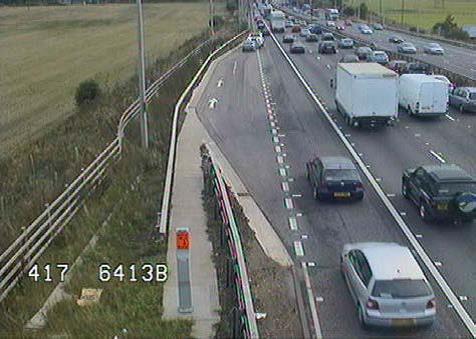
Figure 35. Photo. Emergency Turnout, UK.
(Source: FHWA ATM Screening Guidelines)
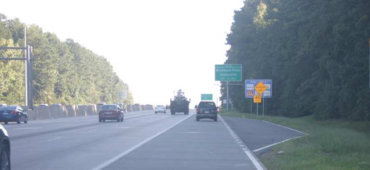
Figure 36. Photo. Emergency Turnout, Georgia.
(Source: Georgia Department of Transportation)
Arterial Part-Time Shoulder Use
There are few unique design considerations for part-time shoulder use on arterials. Arterials, particularly those in urban and suburban areas with recurring congestion, are less likely to have shoulders that are wide enough to be used as travel lanes, and increasing the shoulder width may be less feasible than on a freeway due to the potential presence of curb and gutter, roadside objects, or right-of-way constraints.
All known arterial part-time shoulder use in the U.S. to date have been BOS. Similar to freeways, arterial shoulder lane widths of 10 or 11 feet are adequate on an open section for a low volume of buses at lower, congested speeds and a 12-foot shoulder lane is desirable. A 10-foot lane should not be used if the lateral offset to obstructions is less than the 1.5-foot AASHTO standard or if curbs are present. If curbs are present, then vehicles should be able to remain entirely in the shoulder and maintain a 1.5-foot separation between right side tires and the face of curb.
Examples of signing and pavement marking treatments to accommodate right-turn lanes are shown later in this chapter.
Pavement Design
Part-time shoulder use places vehicles on a portion of the roadway that was not necessarily designed to carry through traffic instead of an occasional stopped vehicle, and an agency should assess shoulder pavement conditions prior to implementing part-time shoulder use. The first step in assessing the adequacy of existing pavement is to estimate the volume and type of vehicles that will use the shoulder. Part-time shoulder use is typically limited to certain hours of the day, reducing volume compared to adjacent general purpose lanes. Shoulders open only to passenger cars will result in only lighter vehicles using the shoulder, while shoulders open to buses will result in heavy vehicles using the shoulder. Bus volumes are relatively straightforward to estimate using known service schedules and expected hours of operation for the shoulder. Structural pavement needs for buses are related to the passenger load, and fully-loaded buses may have as much effect on pavement as a truck. The second step is to conduct a review of the existing shoulder pavement structural section and field assessment of pavement conditions to determine if the available pavement is adequate or if improvements are needed.
If part-time shoulder use is intended to be temporary, such as until a widening project occurs or during construction on an adjacent route, then an agency may find it more economical to routinely conduct maintenance on a shoulder with pavement in poor condition rather than rebuild the shoulder. This strategy is less viable for longer-term part-time shoulder use.(42)
Rumble strips, if used, are typically placed in a position where the tires of a vehicle traveling on the shoulder would track over them. It will generally be necessary to remove existing rumble strips areas prior to implementing part-time shoulder use by milling and resurfacing, and relocate them if they are still desired. MnDOT reinstalled rumble strips on some freeways with BOS operation and placed them on the edge line or in the middle of the shoulder such that buses straddle them.(30)
Minnesota’s experience is that BOS operation typically does not damage shoulder pavement. As of 2007, only one shoulder replacement in Minnesota was due to BOS operation, although others had been repaved, reinforced, or widened. Minnesota now requires a shoulder pavement depth of seven inches for BOS operation. Buses are limited to 35 mph on shoulders in Minnesota to minimize the speed differential with general purpose lanes, and Minnesota reports this also reduces wear and tear on pavement compared to higher speed operation.(42) More generally, the effects of bus speed on pavement wear and tear may vary depending on pavement type and condition.
Drainage Design
Like pavement condition, existing drainage conditions and facilities will need to be assessed prior to implementing part-time shoulder use. On open, uncurbed roadway sections it is unlikely drainage modifications would be needed prior to part-time shoulder uses. On closed section roadways with curb and gutter or other structures such as retaining walls or concrete median barriers that prevent water from running off the road, there are several issues that may be encountered.
Catch basins located in the shoulder not only create potential safety issues and are uncomfortable to drive over, but most are not designed to handle a high volume of traffic driving over them. Minnesota encountered both of these issues after implementing BOS operation, and in response developed a catch basin design specifically for BOS operation.(42) The design brings the inlet flush with pavement and reinforces it with a concrete apron. Massachusetts moved inlets to the edge of pavement,(2) and Virginia relocated inlets on the BOS portion of I-66 that began operation in 2015.(43)
Some portions of a shoulder may have depressed areas to direct water towards catch basins or drainage channels (on open sections). These sections may be uncomfortable to drive over and require resurfacing and relocation of the associated drainage features to provide a smooth ride.
Finally, ponding may occur on shoulders unintentionally (due to pavement imperfections or rutting of pavement(42)) or intentionally due to a design that stores water from a design rainfall on the shoulder. In most climates, these issues should be corrected by improving pavement or adding drainage structures prior to implementing part-time shoulder uses, especially part-time shoulder use by passenger cars. San Diego, which is located in a dry climate, had a BOS pilot project in the mid-2000s that did not improve the pavement, but instead did not allow use of the part-time shoulder use during heavy rain.
In general, many drainage issues associated with part-time shoulder use are most likely to occur on arterials or older freeways. Freeways built in recent decades are less likely to have curbs, catch basins on shoulders, or other unusual drainage features that would require modification.
Traffic Control Device Design
Signing and pavement marking needs vary greatly depending on type of part-time shoulder use. BOS, at one end of the spectrum, is typically implemented as unobtrusively as possible with minimal signing and no pavement marking. Extensive signing and pavement marking is detrimental to overall BOS operation because it leads some passenger car drivers to believe the shoulder is also open to them. Dynamic part-time shoulder use, at the other end of the spectrum, requires changeable signs to notify drivers when the shoulder is open. Static part-time shoulder use has been successfully implemented and operated for decades with static signs, but dynamic signs are becoming increasingly common on these facilities and have been added to several established part-time shoulder use facilities that previously had only static signs to give a higher degree of acknowledgement to drivers of the current operating condition on the shoulder.
This section presents best practices for signing and pavement marking of part-time shoulder use, based on what states have done to date. The Manual on Uniform Traffic Control Devices (MUTCD) does not contain signs or pavement markings specifically intended for roadways with part-time shoulder use, but the principles of the MUTCD can be used to guide the development of such signs and pavement markings.
Bus on Shoulder
Signing and pavement marking needs for BOS facilities are minimal. States such as Minnesota and Virginia that have implemented BOS operation on multiple roadways at different times have determined fewer signs than initially anticipated are needed for BOS operation.(43, 44) Later implementations within these states have used fewer signs than the initial implementations. Limiting signing and pavement marking helps to make BOS operation inconspicuous and reduces the likelihood of the general public believing that they may use the shoulder.(45) TCRP Report 151 provides additional details on signs and pavement markings for BOS facilities. (42)
Signing
Signing on roadways with BOS operation is generally limited to static, ground mounted signs. Most agencies have used black on white, rectangular regulatory signs similar to the R3-10 through R3-12 series of preferential-only lane signs in the MUTCD. Such signs should be installed along a roadway with BOS operation at regular intervals (Minnesota uses one mile spacing) and near on- and off-ramps. They may be supplemented with “begin” and “end” banner plaques at the beginning and end of segments where part-time shoulder use is permitted. Most agencies with BOS operation allow buses to use the shoulder in response to traffic conditions rather than limiting use to certain times of day, so there is typically no need for signs specifying hours of operation. Minnesota experimented with several signs before settling on the sign shown in Figure 37. The word “authorized” is often used for BOS regulatory signs because part-time shoulder use is typically limited to certain transit agencies and/or certain bus drivers who have undergone training.
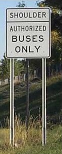
Figure 37. Photo. MnDOT, regulatory sign for Bus-on-shoulder operation.
(Source: Minnesota Department of Transportation)(42)
Along a route, buses sometimes must merge back into a travel lane to avoid a narrow section of shoulder, often on or beneath a bridge. Black on yellow warning signs should be used if this is necessary.
Along on-ramps, some agencies use a “watch for buses on shoulder” warning sign prior to the merge point. On arterials with BOS operation, some agencies use supplemental plaques on stop signs and yield signs on cross streets stating “stop for buses on shoulder” or “yield to buses on shoulder”. Use of warning signs on freeway on-ramps and arterial cross streets is recommended for BOS facilities. Additionally, when a portion of an arterial shoulder is striped as a right-turn lane, a warning sign or a regulatory sign instructing buses to yield to right turn traffic should be considered.
Pavement Marking
BOS operation can be implemented on many freeways with no additional pavement markings being added. Since the mid-1990s, Minnesota has not used any special pavement marking for BOS operation.
The 2009 MUTCD limits use of diamond pavement marking symbols to high-occupancy vehicle (HOV) lanes, and they should not be used on shoulders open only to buses. Previous editions of the MUTCD allowed diamond pavement markings on other types of managed lanes. Minnesota installed diamond pavement marking symbols on shoulders open only to buses in the early 1990s, but removed them because some passenger car drivers believed they indicated the shoulder was open to HOVs and began to use the shoulder as a lane. Word pavement markings such as “bus only”, “transit buses only”, and “transit only” may be placed on the shoulder.
Arterials with BOS operation have greater pavement marking needs than freeways due to bus stops, side streets and driveways, right turn lanes, and other elements of access not present on freeways. Access may also increase the probability of a driver incorrectly believing the shoulder is open to general traffic. Arterial BOS operation is less common than freeway BOS operation, with the majority of US facilities located in Washington State, New Jersey, and Minnesota. Pavement marking needs on BOS arterials is highly facility-specific, and examples from Washington State and New Jersey are highlighted in the Appendix.
Static Part-time Shoulder Use
Signing and pavement marking needs are greater with static part-time shoulder use than with BOS operation because the shoulder is open to the general public. Some static part-time shoulder use facilities utilize dynamic signs, and others have successfully operated with static signs. Signing and pavement marking of static part-time shoulder use is typically supplemented with some degree of ITS, although sometimes ITS is only used to deliver information to facility operators and not drivers. ITS is covered later in this chapter.
Signing
The key signing needs of a static part-time shoulder use facility are to notify drivers that the shoulder is sometimes used as a lane, and to provide the specific times the shoulder is open. Both needs can be met with static signs. However, dynamic signs offer two primary advantages over static signs. First, they can use words or symbols such as a green arrow or red ‘x’ to communicate whether or not the shoulder is open. This reduces the workload on drivers, who otherwise have to read a schedule on a sign, determine the current day and time, and then determine whether or not the shoulder is open. Second, dynamic signs allow facility operators to open or close the shoulder outside of scheduled hours. It is occasionally desirable to do this with a shoulder that is otherwise static in event of disabled vehicles on the shoulder, planned special events generating off-peak traffic, closures of some general purpose lanes for construction or maintenance, or inclement weather. If the project timeline and budget can accommodate dynamic signs, then they should be strongly considered due to the reduction in driver workload, reduced potential for lane status confusion, and flexibility to modify hours of operation.
There are several factors to consider when choosing between static and dynamic signs for a new static part-time shoulder use installation:
- Who uses the roadway? Is it primarily a commuter route or long distance travel route?
- How complex is the part-time shoulder use segment? Are there system interchanges, other managed lanes, or features creating high driver workload?
- How familiar are drivers with part-time shoulder use? Is it the first installation in the region, or are there others?
- How quickly does the project need to be implemented? Is there time to install dynamic signs and communication to them?
- What is the cost of dynamic signs?
Primary static signs regulating part-time shoulder use, or the static portions of the dynamic signs, should be black on white. They may be supplemented with black-on-yellow warning signs.
Signs—static or dynamic—should be provided at the following locations:
- At the start of the part-time shoulder use
- At exit ramps, to manage the conflict of exiting traffic from permanent lanes and through traffic in shoulder lanes
- At and on entrance ramps:
- To notify entering drivers that the shoulder may be used as travel lane
- To manage the conflict between entering traffic and through traffic in shoulder lanes
- At recurring intervals between interchanges
- At the end of the part-time shoulder use
Table 12 lists current static part-time shoulder use facilities in the U.S. and the type of signing used. Georgia plans to convert static signs on GA 400 to dynamic signs and is planning a second set of part-time shoulder use facilities that will initially have dynamic signs. Massachusetts used static signs on their part-time shoulder use facilities for nearly 25 years before adding small dynamic panels to them. Images of signs on the facilities listed in Table 12 are included in Appendix C.
Table 12. Signing of static part-time shoulder use in US.
|
State
|
Facility
|
Type of Signing
|
|
CO
|
I-70
|
Overhead dynamic
|
|
GA
|
GA 400
|
Ground-mounted static (planning conversion to dynamic)
|
|
HI
|
I-H-1
|
Ground-mounted static (Overhead dynamic signs on facility for adjacent reversible lane but not shoulder lane)
|
|
MA
|
MA 3, I-93, I-95
|
Ground-mounted static with dynamic panels
|
|
NJ
|
NJ 29, NJTPK NBE
|
SR 29: ground-mounted static and portable dynamic, NJTPK NBE: overhead dynamic
|
|
TX
|
TX 161
|
Overhead dynamic
|
|
VA
|
I-66, I-264
|
Overhead dynamic and ground-mounted static
|
|
WA
|
US 2
|
Overhead and ground-mounted static
|
NJTPK NBE — New Jersey Turnpike Newark Bay Extension
Similar to exit ramps on a freeway, a series of signs provided in advance of a turnout and at the turnout itself is recommended to increase driver awareness of its existence. In 2007, Virginia modified turnout signing on I-66 from one small sign at the turnout itself to a sequence of typical freeway size signs, and this change has led to increased use of turnouts.(43) Turnouts can be signed with black on white regulatory signs (generally consistent with other signs related to part- time shoulder uses) or green guidance signs (consistent with exits). Preference will likely be determined in the next edition of the MUTCD.
Pavement Marking
Pavement markings for static part-time shoulder use should provide effective guidance to drivers when the shoulder is both open and closed to traffic. On basic segments away from ramps, this is straightforward and there is consistency across states:
- The solid edge line typically used between the shoulder and adjacent travel lane remains in place.
- A second solid line is used on the outside of the shoulder beside the edge of pavement. This line functions as an edge line for traffic using the shoulder. The second solid line should be continuous even when the shoulder narrows or has a physical barrier beside it, such as a bridge rail.
- The two solid lines should be the same color—white for part-time use of the right shoulder and yellow for part-time use of the left shoulder.
Pavement markings at the start and end of part-time shoulder use segments and through ramp freeway junctions were discussed in the Geometric Design section of this chapter. Pavement markings at on- and off-ramps are more complex, and example markings were previously shown in Figure 27 through Figure 34. They vary based on the types of entrance and exit configurations described in the geometric design section of this chapter, and existing state ramp-freeway junction marking practices. In general, pavement markings in the vicinity of a ramp-freeway junction should provide a clear means for drivers on the mainline shoulder to pass through the ramp freeway junction, and they should also provide a means to transfer from the freeway to ramp or vise verse. Striping can create parallel or taper style merges and diverges.
Colored Pavement
The Section 3G of the 2009 MUTCD and an interpretation letter specify the use of colored pavements for the following situations:
- Yellow pavement for median islands separating traffic flows in opposite directions or left shoulders of divided highways or one-way streets or ramps(5)
- White pavement for channelizing islands or right-hand shoulders(5)
- Green pavement for bicycle lanes(6)
- Red pavement for streetcar and/or bus-only lanes on an experimental basis(6)
No color is designed for part-time shoulder use, and none should be used at this time unless a request to experiment is submitted to and approved by the MUTCD team.
Dynamic Part-Time Shoulder Use
Dynamic part-time shoulder use requires dynamic signs to communicate whether or not the shoulder is open to traffic. Pavement marking needs for dynamic part-time shoulder use is no different than static part-time shoulder use. In both cases, pavement markings need to provide sufficient guidance to drivers when the shoulder is open and when it is closed.
ITS Design
Most part-time shoulder use facilities are accompanied by ITS, and dynamic part-time shoulder use requires it. ITS includes:
- Speed sensors and cameras to help agencies monitor and manage the facility in real time
- Electronic lane control signs (LCS)
- Changeable message signs (CMS)
- Driver information ITS treatments to communicate information such as when the shoulder is open to traffic
- Regulatory and warning signs that must be turned on and off as the shoulder opens and closes
The 2006 FHWA scanning tour of ATM systems in Europe identified several recommendations for active traffic management strategies on facilities with part-time shoulder use:(46)
- Changeable message signs to provide guide sign information and regulatory signs to adapt to the addition of the shoulder as a travel lane. The signing should be uniform, with adequate installation of sign gantries to provide operational information and to ensure it is in sight at all times.
- Closed-circuit television cameras with sufficient coverage to verify the clearance of the shoulder before deployment.
- Comprehensive incident management program, including advanced incident detection capabilities.
This section addresses the potential ITS design treatments and associated issues.
Signs
Lane-Use Control Signals for Shoulder Use
Dynamic part-time shoulder use requires electronic lane-use control signals (LCS) to display whether the shoulder is opened or closed to traffic or, optionally, transitioning from being open to closed Static part-time shoulder use facilities can benefit from LCS as well, as they allow occasional deviation from operating hours due to disabled vehicles, off-peak special events, or other nonrecurring events.
The MUTCD (Section 4M.02 — Meaning of Lane Use-Control Signal Indications) identifies the following displays for lane control:
- A steady DOWNWARD GREEN ARROW signal indication shall mean that a road user is permitted to drive in the lane over which the arrow signal indication is located
- A steady RED X signal indication shall mean that a road user is not permitted to use the lane over which the signal indication is located.
- A steady YELLOW X signal indication shall mean that that a road user is to prepare to vacate the lane over which the signal indication is located because a lane control change is being made to a steady RED X signal indication.
The MUTCD requires lane-use control signals to remain on and not be dark. In general, the YELLOW X has not been used for part-time shoulder use or for the broader dynamic applications. The initial applications of ATM in the United States—Seattle, Washington and Minneapolis, MN—have used other yellow displays. Use of yellow displays other than an X is not consistent with the MUTCD and requires a request for experiment. Additional information on this process is included in CHAPTER 9. An ongoing FHWA study has been evaluating ATM sign displays and to identify potential gaps in the MUTCD in this regard.
Changeable Message Signs
In addition to lane control signs, changeable message signs (CMS) can be used to reinforce the open/closed status of shoulder or provide other information to drivers. High volume, urban freeways on which part-time shoulder use is typically implemented often already have CMS signs.
Dynamic Speed Limits with Part-Time Shoulder Use
Depending on the lane widths (both the shoulder and mainline), the types of vehicles allowed to use shoulder, the possible reduced sight distance around curves (as seen from the part-time shoulder use), the potential for reduced clear zone distances when part-time shoulder use is in operation, and the configurations of the mainline and ramp shoulders in the vicinity and through interchanges, it may be appropriate to reduce the speed limits during part-time shoulder use operation. If a state does not have the legal authority to vary speed limits, legislative changes may be needed so dynamic speed limits can be implemented. Enforcement of dynamic speed limits also presents challenges because the police must be informed in real time of the speed limit and have a record of speed limits used at all times for court purposes.
Mainline Dynamic Lane Assignment and Dynamic Speed Limits
The UK’s “Smart Motorway” concept (formerly known as “Managed Motorway”) includes the use of dynamic speed limits and dynamic lane assignment (with lane-use control signals) across all lanes, in addition to dynamic part-time shoulder uses. In Europe, dynamic part-time shoulder use is almost always deployed in conjunction with dynamic speed limits and dynamic lane-use control signals for all lanes along with queue warning.
While this has not been the practice to date in the U.S., consideration should be given to this approach if dynamic part-time shoulder use is being installed, particularly along segments experiencing high frequencies of rear-end or side-swipe crashes. Additional information on identifying roadway segments where the application of dynamic speed limits and dynamic lane assignments may be cost effective can be found in the FHWA document Active Traffic Management (ATM) Feasibility and Screening Guide.(47)
CMS Spacing — Static Part-time Shoulder Use
States with static part-time shoulder use are increasingly using changeable signs to supplement the static signs regulating the hours of operation of the shoulder lane. This reduces driver workload by clearly communicating whether the shoulder is open or closed, and it provides flexibility to occasionally deviate from normal operating hours. If used, supplemental dynamic signs should be placed at the same locations as static regulatory signs displaying operating hours of the part-time shoulder use. Typically, this is at the start of the part-time shoulder uses segment and after on-ramps.
CMS and LCS Spacing — Dynamic Part-Time Shoulder Use
The effectiveness of any ATM approach requires that drivers recognize and understand they are driving on an actively managed facility. How this “continuum of information” is provided has a significant impact on dynamic part-time shoulder use costs, particularly if other ATM treatments are also provided.
The initial deployments of ATM in the United Kingdom used gantries spanning the entire roadway with LCS displaying speed limits and lane control over each lane—including the shoulder, where applicable. Larger CMS on the side displayed queue warning messages and other information. These gantries were spaced such that drivers could see the next gantry immediately after passing under a gantry, resulting in a gantry spacing of 600 meters (0.37 miles) to 1,000 meters (0.62 miles). The concern was that compliance would be less if gantries were spaced too far apart. The spacing of gantries for the Washington State and Minnesota ATM systems followed suit and are located at roughly 0.5-mile intervals on average. If only part-time shoulder use operation is implemented—with a cantilever sign and LCS over the shoulder—then this approach (sign approximately every 0.5 miles) is appropriate. However, if other ATM treatments such as mainline lane assignment and variable speed limits are deployed, then placing a LCS over every lane requires a gantry structure like the ones in Figure 38, and this significantly increases project cost. In these cases, sign spacing greater than every 0.5 miles may be appropriate.
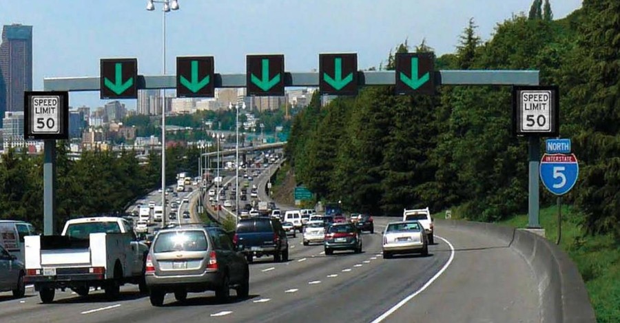
Figure 38. Photo and Illustration. Example of full gantry ATM deployment in Washington State (no part-time shoulder use).
(Source: CH2M)
In the U.K., gantry spacing of 600 to 1000 meters used on early ATM facilities is now considered conservative, and experience indicates that greater gantry spacing may be adequate. The current U.K. philosophy is that spacing needs to be sufficient so that drivers know they are still on a controlled roadway.
Cantilever signs that diagrammatically indicate lane status and gantry signs similar the one in Figure 38 were determined through a driver simulator trial to be comprehended equally well by U.K. drivers. The overall results suggested that cantilever signing is equal to gantry-mounted signing at instructing drivers to move out of a particular lane.
The latest Smart Motorway design concepts from the U.K. Highways Agency for dynamic speed limits, dynamic lane assignment (including shoulders) and queue warning consist of the following:(48)
- Driver information, including speed limits, lane availability and closures, and text legends (e.g., queue warnings) and pictograms is provided at intervals not exceeding 1,500 meters (0.93 mile). This can be provided via gantry or cantilever signs (referred to as “verge-mounted”.
- The first sign display downstream of an on-ramp is a gantry with lane signs (for displaying dynamic speed limit and dynamic lane assignment messages) over each lane and a CMS for other messages of a strategic nature.
Based on the U.K. work, a “hybrid” approach has been developed for planned installations of dynamic part-time shoulder use and other ATM treatments in New Jersey and Pennsylvania consisting of gantries every mile, with cantilever dynamic speed limit signs (located on both sides of the roadway) between each set of gantries.
CCTV and Detection
The aforementioned Smart Motorway design concepts from the UK Highways Agency also calls for full coverage of CCTV equipped with pan, tilt, and zoom. This allows viewing the entire length of the shoulder prior to initiating shoulder operations (i.e., verifying the clearance of the shoulder before deployment) and to identify and verify roadway conditions during incidents and other events. Many static part-time shoulder use facilities in the U.S. are manually inspected by police driving the corridor prior to the opening of the shoulder each day. This approach is less feasible for dynamic part-time shoulder use with varying hours of operation, and full CCTV coverage is recommended for dynamic part-time shoulder use.
With dynamic part-time shoulder use, the software algorithms at a TMC determining when to open and close the shoulder will likely require a high density of detectors, measuring volumes (including the part-time shoulder use) and spot speeds (for each lane including the shoulder) at each gantry/sign location. These data are also used to vary speed limits and provide queue warnings if this is done on the facility.
If there are weather-related concerns about part-time shoulder use, such as ponding of water, buildup of snow and ice, or reduced visibility due to fog, then consideration should also be given to the installation of road weather information sensors to determine the condition of the pavement and air. This information can be used to help determine whether the shoulder should be opened to traffic and to determine appropriate speed displays if variable speed limits are in place.