Best Practices for Road Weather Management
Minnesota DOT I-35W Smart Lanes: Active Traffic Management
Minnesota’s Smart Lanes is the brand name of the Active Traffic Management (ATM) system on I-35W in the Twin Cities Metro Area. The ATM system was deployed on Interstate 35 West (I-35W) in two phases between 2009 and 2010. The original system covered sixteen miles of I-35W south of Minneapolis and was extended by two miles in 2011. A new eight-mile section of ATM is being installed on Interstate 94 (I-94) between downtown Minneapolis and downtown St. Paul and was scheduled to be activated in the summer of 2012.
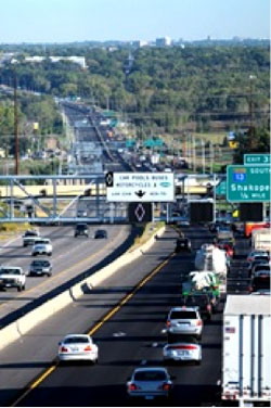
ATM consists of electronic signs over lanes of traffic (see Figure MN-1) to provide real-time information to help motorists make informed decisions about their commute. The signs display information about road conditions to improve traffic flow, reduce congestion and improve safety.
The signs are illuminated during traffic incidents to indicate whether lanes are open to traffic. This use of technology will enhance safety and improve the flow of traffic by providing motorists information about the conditions within their lane (and alert them to what is ahead). The information provided by these overhead lane signs will be real-time, designed to help motorists navigate safely through traffic. The ATM system was modeled after similar systems in Europe that have been proven effective at reducing collisions and improving traffic flow.
The ATM system is operated out of the Regional Transportation Management Center (RTMC). The RTMC is a co-located operations center housing Minnesota Department of Transportation (MnDOT) freeway management staff, Freeway Incident Response Safety Team (FIRST) dispatch, MnDOT arterial management staff, MnDOT maintenance dispatch, and State Patrol metro area dispatch. From the RTMC, MnDOT operates a Freeway Management System (FMS) covering over four hundred miles of Twin Cities Metro Area freeways including the I-35W ATM corridor. The system includes loop detection, dynamic message signs (DMS), ramp meters, cameras, and fiber optic communications. The existing FMS provided the backbone for the ATM system deployed on I-35W.
MnDOT has a freeway traffic management system software known as Intelligent Roadway Information System (IRIS). IRIS was developed in-house to communicate and control loop detectors, DMS, and ramp meters. The software was expanded to control the ATM system.
System Components: A series of overhead signs known as Intelligent Lane Control Signals (ILCS) above each lane on I-35W are used to inform drivers of upcoming conditions or controls in place. Overhead signs are used to indicate which lanes are closed to access, blocked because of a crash or obstruction, and which adjacent lanes are impacted by such events. The ILCS are used to post advisory speed signs, warning travelers to slow in anticipation of stopped traffic ahead.
The ILCS are located along northbound and southbound I-35W from I-35 to the I-35W split with Highway 65. Spacing of the signs is approximately one-half mile apart. The exact spacing is based on relations to bridges, existing signs, sight lines and budgets.
Existing overhead signs and High Occupancy Toll (HOT) lane signs are incorporated on same sign structures as ILCS. Sign structures are placed in accordance with sign spacing requirements. Sign structure placement will be determined in the design stage.
At key locations along I-35W, ILCS are used to inform drivers of closed lanes and/or recommended speed limits. The managed lane control system essentially serves four key purposes:
- Inform drivers when the left lanes are open to High Occupancy Vehicle (HOV) and/or HOT lanes;
- Inform drivers of advisory speed limits (when necessary) in order to slow traffic that is approaching stopped traffic (At this time, uniform speeds are posted across all lanes. MnDOT has not ruled out the idea of varying speeds in lanes and may opt to implement this in the future);
- Inform drivers of lanes closed (such as when dynamic shoulder lanes are closed or when general purpose lanes are closed due to a crash or stalled vehicle); and
- Inform drivers of hazards such as standing water or debris on the roadway and encouraging travelers to merge away from the hazardous lanes.
The signs over each lane are used to display one of eight messages, as shown in Figure MN-2 and summarized as follows:
- Blank (black sign)—to be used as the default display. To be effective ILCS messages should be timely, accurate, and reliable. Displaying other default messages would distract from normal signing and would dilute effectiveness when really needed.
- Red “X”—to be used to indicate that the lane is closed to traffic or has an incident, crash or other obstruction. Emergency vehicles and other incident responders would be allowed to use the lane to respond to blocking incidents quicker.
- Advanced Yellow “X”—to be used to indicate that the lane will be closing one mile ahead because of an incident, crash, or other obstruction.
- Merge with moving chevron—to be used to indicate traffic should merge right or left as the lane is closed ½ mile ahead because of an incident, crash, or other obstruction.
- Yellow Flashing Arrow—to be displayed on lanes adjacent to a closed lane (each Red “X” will be surrounded by yellow flashing arrows.)
- Green Arrow—to be displayed during an incident above those lanes not affected by the incident (a red “X” will be above the lane with the incident, flashing yellow arrows above adjacent lanes, and green arrows above other lanes.)
- Advisory Speed—displayed as a two-digit number with “MPH.”
- White diamond—to be used to indicate lane use as exclusively for vehicles with high occupancy.
System Operations: The managed lanes are controlled by RTMC operators from within the RTMC. Operators have full authority to select from available messages, after events are verified.
The display of lane advice depends on the location of any lane obstructions and the resulting Red “X” signal indicating lane closure. Advanced warning messages are posted on all signs located upstream of the blockage within a distance of at least one mile. As motorists approach a closed lane they will encounter an Advanced Yellow “X” sign one mile before the closure. The next sign will display a “Merge with Arrow” within a half mile of the actual Red “X” sign over the lane that is closed. This is to ensure that travelers have advanced warning of the closure before reaching the incident. Further upstream, the signs will display an automated advisory speed posting which will change based on real time traffic conditions. This is explained in the next section.
When display signs are posting either a Red “X” or yellow flashing arrow message, all other signs will display a green arrow. Figure MN-3 shows an example of signing for a crash blocking a lane and activating Advisory Variable Speed Limits.
Figure MN-3. Example of display of intelligent lane control signals during an incident.
The selection of advisory variable speed limits (VSL) is computed by an algorithm developed by the RTMC and the University of Minnesota—Duluth. RTMC operators have the option to override the calculated advisory speeds or to accept the recommendation and verify the posting of the message.
The goal of the advisory VSL system is to mitigate shock wave propagation from downstream bottleneck by gradually reducing speed levels of incoming traffic flow. Figure MN-4 illustrates how speed data is collected through traffic sensors on the roadway at point locations shown as black circles on the chart. Without advisory VSL, vehicles approaching congested traffic are forced to change speeds within a very short distance leading to sudden stopping and possible rear end collisions. The advisory speed limits are posted to allow for a more gradual deceleration between upstream free-flowing traffic and congested traffic. The speeds displayed on the ILCS would gradually reduce traffic speeds as shown by the yellow boxes in the figure.
As congestion levels develop, two or three sets of signs prior to the congestion display an advisory speed limit based on the algorithm depending on what the speed differential is between upstream and downstream traffic. Speeds can be posted up to 1.5 miles upstream of congestion.
Advisory speeds posted to the overhead signs change by no more than five miles per hour (MPH) with each change in speed, and can be updated every thirty seconds if traffic conditions warrant. The minimum advisory speed displayed is thirty MPH and the maximum advisory speed displayed is fifty MPH. If the current speeds on the roadway are below thirty MPH the signs will go blank.
Transportation Outcome(s): This use of technology will enhance safety and improve the flow of traffic by providing motorists information about the conditions within their lane (and alert them to what is ahead).
Implementation Issues: There are currently several implementation issues that MnDOT is resolving, particularly with regards to expanding the ATM from incident-based traffic management to weather-based traffic management. Additionally, dynamic lane striping and signaling was a challenge in implementing the full system.
MnDOT is currently researching how to modify the advisory speed limit during inclement weather. Currently the system uses a constant deceleration rate to determine advisory speed limit values. Observations of the system have found that the preferred deceleration rates may be different during different kind of weather conditions. An observation of the system found that the maximum speed value needed to be adjusted due to weather conditions. Historically, the maximum speed limit of the system was capped at 5 MPH less than the posted speed limit. This value was changed to a maximum of 50 MPH for all corridors when it was found that the system would deploy 60 MPH on the corridor during major snow events. MnDOT is working to develop new techniques for the advisory variable speed limit system during weather events that would automatically adjust the deceleration rate and the maximum speed value based on real-time weather conditions on the corridor. The VSL system would utilize rain sensors on the corridor to inform the system of what type of precipitation was falling and at what rate.
Along the southern half of the I-35W corridor there are sections where the left lane of traffic was shifted onto the inside shoulder by two feet to allow for a buffer zone between the new HOT lane and the general purpose lanes. This inside shoulder was originally designed to allow for some ponding during heavy rainfall. Now that traffic is shifted onto these shoulders, there is a potential for hydroplaning during heavy rainfall as the shoulder area begins to fill up with water. MnDOT is investigating the use of rainfall sensors to automatically deploy either a warning message or advisory speed limit over this lane during these conditions.
The physical width of the stretch of I-35W northbound from 42nd Street to downtown limits the number of lanes and shoulders. The I-35W ATM system includes the concept of a dynamic shoulder lane in the left-most lane along this stretch of road. This left-most dynamic shoulder lane operates as a
- priced dynamic shoulder lane at times when the adjacent stretch of I-35W is operated as a HOT lane,
- priced dynamic shoulder lane at times when the capacity is needed, and
- shoulder when needed.
The dynamic shoulder lane is separated from the general purpose lanes by a single solid yellow stripe. An additional yellow stripe was placed along the center median barrier to improve visibility. A static sign is placed at the beginning of the dynamic lane (Figure MN-5).
A computer simulation of the dynamic shoulder lane entrance indicated that MnDOT needed to enhance the pavement marking to inform motorists whether the priced dynamic shoulder lane (PDSL) was opened or closed. For this reason it was determined that in-roadway lighting was best suited for this project. In the transition zone, an LED in-roadway lighting system was developed to alert traffic to merge right when the PDSL is closed (Figure MN-6). The LED lights were the same color as MnDOT’s standard yellow striping and were dimmable for night time driving. The in-roadway lighting was able to be changed to a white LED light when the PDSL is open that will extend the existing white skip striping into the dynamic shoulder lane (Figure MN-7). After two seasons, the LED in-roadway lighting system failed due to corrosion in the power connections within the LED units. Analysts compared violation rates of the PDSL merge area with and without the in-roadway lighting and found no distinguishable difference in the amount of violators in the PDSL without the lights. Due to the high cost of replacing the system, MnDOT is not planning to bring the LED in-roadway lighting back into service.
Figure MN-6. Striping and signing with PDSL closed.
Figure MN-7. Striping and signing with PDSL open.
Lane widths for the dynamic shoulder lane and the general purpose lanes vary from 11 feet to 12 feet. Between the dynamic shoulder lane and the general purpose lanes is a two foot buffer. Reaction distance from the dynamic shoulder lane to the center median barrier varies from 2.5 feet to six feet. Static signing as shown in Figure 4 together with intelligent lane control signals will designate when the shoulder lane is open to traffic.
After the first several snowfalls, MnDOT Maintenance staff recommended that the dynamic shoulder lane remain open during snow and ice events to help spread the de-icing material throughout the lane. During off-peak periods when no vehicles were present on the dynamic shoulder lane, de-icing materials were not able to be spread out by passing vehicle traffic thus leaving icy patches across the lane. By leaving the lane open to traffic, just enough vehicles used the lane to keep de-icing materials spread out and keep the lane free of ice.
Contact(s):
- Brian Kary, Freeway Operations Engineer, 651-234-7022.
Reference(s):
Keywords: Dynamic Message Sign, traffic management, incident management, weather management, incident response, intelligent signage, variable speed, variable lane configuration, advisory speed, dynamic pricing, dynamic shoulder.
previous | next