Rural Interstate Corridor Communications Study
Report to States
2.0 Preliminary Backbone Alignments
As part of the task to develop the Report to States, preliminary backbone alignment plans for telecommunications (fiber/conduit routing and tower locations) have been developed and presented in electronic format. The purpose of the preliminary backbone alignment is to offer a high-level preliminary design to enable State agencies or private telecommunications partners to begin the process of developing estimates of the level of effort required to install telecommunications infrastructure. The backbone infrastructure included in this study includes wireline infrastructure (conduit buried to house fiber optic cable) and wireless infrastructure, such as tower locations.
The major elements considered in developing the preliminary backbone alignment include:
- Constructability (the physical challenges to be addressed in deploying the fiber optic cable or wireless infrastructure);
- Scheduling (a rough estimate of how long construction would take once deployment commences);
- Capital cost (built up from typical unit costs for equipment and installation);
- Maintenance and operating costs (including consideration of maintaining the telecommunications infrastructure with in-house or contract maintenance support);
- Environmental challenges that may be encountered in each corridor and
- Policy considerations, including the advantages and disadvantages of different utility accommodation policies, and the potential for public-private or public-public partnerships for deployment.
The products of the Rural Interstate Corridor Communications Study are informational only. This study does not obligate Federal, State, or local governments to implement any of the study findings. The products of the study are intended only to inform the public and elected officials.
2.1 Backbone Alignment Development Process
The study team met with the ten States involved in this study in several settings, including Corridor-wide meetings held in central locations along the Corridor and individual State by State meetings. These meetings all took place between February and May 2007.
State DOT stakeholders were important participants of this study. Each State provided important baseline information including utility accommodation policies, as-built information, and plans for ITS and HST in the State. Once this baseline information was collected and reviewed, the project teams visited with each State to go over the existing conditions and discuss implementation issues.
For this study the preliminary backbone alignment plans have only been developed for two of the three Corridors identified in Section 5507 of SAFETEA-LU: Interstate Highway 90 and Interstate Highway 20. MassHighway and the Vermont Agency of Transportation along the Interstate Highway 91 Corridor had independently progressed in the development of a Corridor communications program to the point where developing a preliminary backbone alignment as defined by this study would have been of little value. Instead, the study team has developed a series of typical telecommunication installation details that can be used for future telecommunication construction projects. The typical installation details, listed in Appendix C, are on plan sheets in Microstation and AutoCAD 2007 software format, and can be manipulated into a plan sheet based on the requirements of the agency preparing plans. Prints of all typical installation details developed, including electronic files, are under separate cover from this report and are available from the FHWA.
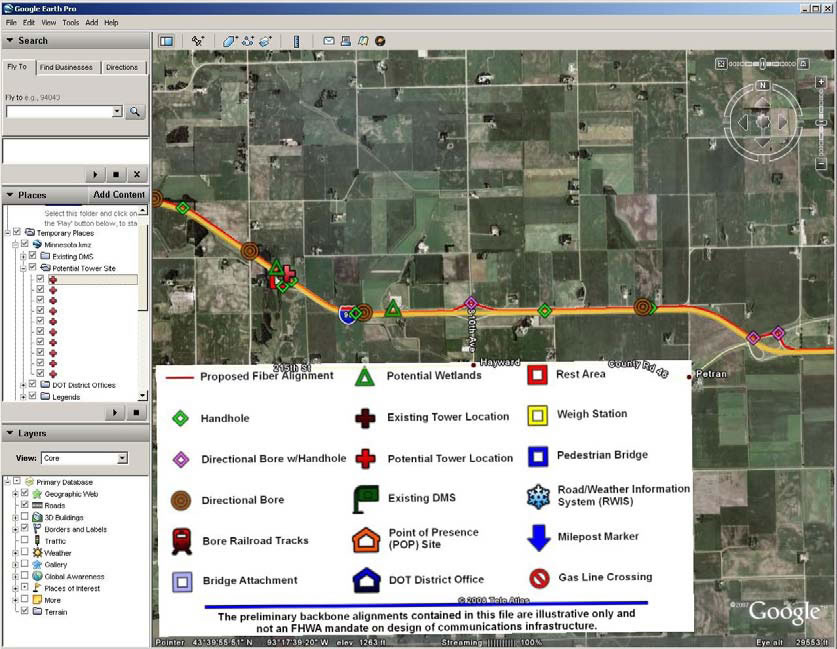
The study team was challenged with how to generate and present a HST preliminary backbone alignment that would be relevant and useful for the corridor States without developing detailed plan sheet that would become out-of-date prior to a project taking form. The traditional method of delivering plans would consist of hard copies of plan sheets. Advances in freely available mapping programs on the Internet led the team to investigate and ultimately use satellite imagery for displaying the preliminary backbone alignments. The study team determined that electronic files utilizing Google Earth as a base map would provide the most flexibility for storing, displaying, and using the preliminary backbone alignment files. This approach also allowed Corridor States to update and maintain the files for use after the conclusion of the study. The electronic Google Earth KML (KML, or Keyhole Markup Language, is an XML grammar and file format for modeling and storing geographic features such as points, lines, images, polygons, and models for display in Google Earth and Google Maps. KML can be used to share places and information with other users of Google Earth and Google Maps) files have been enhanced with the addition of lineation, symbols, and icons representing various existing and proposed infrastructure elements and an example of this is show in Figure 2-1. A final design step was a visual survey of the corridors conducted by the project team. This driving survey allowed the team to resolve questions and issues due to less than ideal satellite imagery, as well as identifying corridor conditions that would otherwise be overlooked.
Figure 2-1 Typical Section of I-90 Corridor using Google Earth as a base map
Included in this report is information related to how the preliminary alignments were developed, and how information developed by the study team can be utilized by the Corridor States in the future. The details included in the alignment files, including criteria for placement, are defined below. The electronic files can be obtained from the FHWA.
The intent of Congress appears to be to provide a look ahead toward a point where Corridor-wide projects could be developed to install a contiguous communication backbone. This backbone infrastructure would serve the needs of each State as well as the communication needs of the communities along that Corridor. It is understood that each State has unique rules and policies that must be adhered to and that those polices will be applicable to any utility work within each State. Therefore, the information presented here looks at each Corridor as a whole while explaining some of the specific issues unique to each State.
2.2 Preliminary Backbone Alignment Design Elements
It should be noted that the preliminary backbone alignments developed as part of this study are, as the name suggests, preliminary and should not be considered a final design nor taken as any indication that a future project to install infrastructure of this type is imminent. The preliminary backbone alignments contained in these files are illustrative only and not an FHWA mandate on design of communication infrastructure. They are intended for information purposes such as preliminary estimation of quantities, identification of construction issues, and preliminary cost estimation to aid in discussions with potential private partners. If a State agency or private provider wishes to use the files to create more detailed designs, such use is allowed and encouraged.
The design criteria presented here acknowledge that to the greatest extent possible, preliminary designs for all utility infrastructure installed on State-owned access-controlled ROW must be consistent with the State's Utility Accommodation Policy (UAP) and the laws and requirements of the State. Before final designs are completed, the policies and regulations of each State should be consulted and adhered to in the final design plans. Private partners involved in the installation of telecommunications infrastructure on State ROW also may have criteria to be considered in the final designs of such infrastructure. The backbone alignments generated as part of this study are preliminary in nature and the UAP and laws of the State would influence final design.
The preliminary design elements included in the Google Earth KML files are presented below along with suggestions regarding the use of the information.
Fiber Optic Line Placement
The preliminary backbone alignment files show the routing of conduit where a fiber optic line would be placed along the right-of-way. The design assumes that conduit for fiber optic cable will be installed by plowing or trenching methods with directional boring to navigate under roadways, streams, or other obstacles. Decisions about the side of the right-of-way in which the conduit is to be placed were based on several factors, including width of ROW, potential obstacles, presence of rock or environmentally sensitive areas, and access for heavy equipment and maintenance personnel.
Handhole/Vault Location
Handholes/vaults are used to access the conduit and fiber optic cable for making splice connections or for the installation of fiber optic cable into the conduit. In this document, the terms handholes and vaults are considered interchangeable and represent a box to accommodate all aspects of fiber optic cable installation such as pulling points, coiling, splicing, etc. For this design handholes have been placed at interchanges, tower locations, weigh stations, and rest areas. For the purposes of pulling fiber into the conduit, handholes are generally located at one-mile intervals (minimum) where the above criteria cannot be met within that distance.
Regeneration Building Placement
Regeneration stations or POP (Point of Presence) sites are locations where the signal being transmitted through fiber optic cable is regenerated and transmitted further along the fiber optic path. These POP facilities are also utilized as a location where connections to local networks are made. The criteria for placement of the regeneration buildings are based on the ability of existing fiber optic transmission equipment and cable to transmit a signal an average of 50 miles. Regeneration stations require access to electrical power, an important design consideration. Proposed regeneration buildings have been placed as closely as possible to 50-mile spacing where access is easily gained from a side road or other non-mainline access, such as an interchange or rest area. Regeneration building sites should have sufficient space to accommodate a 10' x 20' one-story building with room for parking one or two vehicles. A perimeter fence may be needed to secure the site (approximately a 1000 sq. ft. footprint). These facilities should be located outside of the clear zone.
Directional Boring
Directional boring would be used at small stream crossings, where bridge attachments are not practical or not allowed by the State, at roads and railroads crossing under or over the Interstate highway, at interchanges, and at existing utilities (such as gas or oil pipelines). The preliminary design indicates directional bore locations with one icon representing the directional bore area versus two icons representing the entrance and exit bore pits. Where applicable, an icon representing a directional bore and handhole, such as at an interchange, has been used to minimize the number of icons at interchanges.
Bridge Attachments
The criteria to determine bridge attachments versus directional boring under a river or stream will depend on State policy and approval. An application for a bridge attachment permit should be submitted when route design plans are submitted by the private entity or private partner prior to final design stage. For the purposes of the preliminary backbone alignment, bridges that span major rivers, railroad yards, or complicated interchanges are shown as bridge attachments (with permit approvals needed prior to final design). For bridge attachments, conduit should be encased in a bullet-proof shroud, located on the downstream side of the bridge, or protected by bridge beams to prevent damage from floating debris, and meeting all State standards for attachment of fixtures to bridges.
Communication Tower Locations
Communication towers shown on the preliminary backbone alignments include existing public agency-owned communication towers and privately owned communication towers. This includes DOT-owned towers, other public agency towers, and towers indicated on the tower maps obtained by the project team. Potential tower locations to be considered for construction at a future date are indicated with an icon. The proposed tower locations allow for sufficient space for the towers and associated structures on public agency-owned ROW. The sites include a handhole and are potentially co-located with a regeneration building due to the availability of ROW associated with a tower site. If the States have identified locations where they are willing to allow a tower to be located, these are also shown.
Towers for use in the backbone become critical when construction of a fiber link is cost-prohibitive or physically difficult. Most tower locations shown on the preliminary backbone alignments are locations that would support middle or last mile connections, though some do represent where backbone links could be installed to reduce installation costs. Spacing of the towers for the backbone becomes dependent upon the transmitting and receiving equipment as well as the frequency used, so tower locations would have to be further designed to accommodate any backbone linkages that may be desired.