Traffic Analysis Toolbox Volume VI:
Definition, Interpretation, and Calculation of
Traffic Analysis Tools Measures of Effectiveness
6.0 Recommended MOEs
This chapter presents the recommended set of MOEs along with their recommended method of computation and interpretation.
6.1 Recommended System of Key Systemwide MOEs
Traffic operations analyses can generate a great deal of numerical output. Any one of the numerical outputs can be important to the analyst depending upon the purpose and scope of the analysis and the alternatives being evaluated. The set of key systemwide MOEs recommended below is designed to be the "starting set" but not the end all set of MOEs for any traffic operations analysis.
This basic set is kind of like the first set of exams given to every patient when they first check into the emergency room. It does not matter what the patient's complaint, the same four measurements are gathered and reported for every emergency room patient: temperature, pulse, blood pressure, and blood oxygen. These four basic indicators give the doctors a basic understanding of the general health of the patient, and some indication of general fields to investigate for the source of the problem. But they are not the definitive diagnostic tests. They are not the MRIs, X-Rays, or exploratory surgery that come later.
Similarly, our basic system MOEs are designed to be that first round of tests every traffic engineer and planner should perform to assess the general health of his or her transportation system. They give an indication of the overall health of the system, and how serious the problems are. But they do not necessarily tell the engineer/planner precisely what is wrong. That is the purpose of additional analyses and additional tests.
So this basic set of MOEs is not designed to replace the more detailed intersection and segment MOEs engineers and planners already are accustomed to perform to diagnose and solve traffic operations problems on the transportation system. This basic set is designed to help the engineer/planner and decision-maker rapidly assess the state of the system and identify key avenues of additional analysis to better identify needed improvements.
This basic set of MOEs also is good for rapidly assessing the benefits of alternative improvements at the system level, in a form readily understandable by the decision-maker.
The basic set of MOEs for decision-making consists of five basic measures:
- Throughput;
- Mean Delay;
- Travel Time Index;
- Oversaturated Freeway Segments; and
- Surface Street Intersections with Turn Bay Overflows and Exit Blockages.
Each of these basic MOEs is highlighted in Table 29. Their use, definition, computation, reporting, and interpretation are presented in this table.
Table 29. Key Measures of Effectiveness for Decision-Making
Decision MOE |
Use/Description/Interpretation |
|---|---|
Throughput (Vehicles/hr) and Percent Incomplete Trips |
|
Delay/Trip |
|
Travel Time Index |
|
Freeways: Percent Breakdowns |
|
Surface Street: Percent of Intersections Exits Blocked |
|
There are, of course, many other MOEs that every good planning or engineering study also will want to consider, such as, user benefits, user costs, fuel consumption, noise, air pollutant emissions, and safety. However, the five basic system MOEs listed above will give the decision-maker and the analyst a good idea of how well the system is performing and how one alternative improvement compares to another. The text below describes them in more detail.
Throughput
Throughput is an indicator of the productivity of the system. It tells the analyst how many vehicles were processed by the system during the analysis period. A related indicator is the percent of trips that were initiated during the analysis period but could not be completed during the analysis period. Throughput plus the percent incomplete trips tell the analyst how good a job the system is doing at moving vehicles.
If the analyst's goal is to move people rather than just vehicles, throughput and percent incomplete can be computed based on person trips rather than vehicle trips. It is a straight forward conversion requiring only knowledge of the vehicle occupancy (number of person per vehicle).
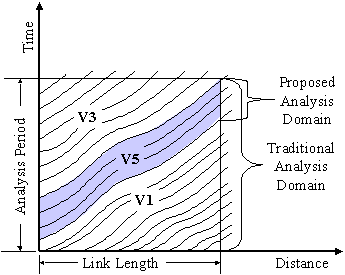
Throughput is defined as the number of distinct vehicles (or people) able to enter or exit the system during the analysis period. To aid its interpretation, the throughput should be divided into five components according to whether or not the vehicle entered, exited, never entered, or never exited the system during the analysis period (see Figure 5).
Figure 5. Illustration of Different Components of Throughput
Vehicles Class I = Vehicles that were present at the start of the analysis period and were able to successfully exit the system before the end of the analysis period.
Vehicle Class II (not shown in figure) = Vehicles that were present at the start of the analysis period but were unable to successfully exit the system before the end of the analysis period. Except for severe congestion cases or very short analysis periods, this class of vehicles is usually zero.
Vehicles Class III = Vehicles that were able to enter the system during the analysis period but were unable to successfully exit the system before the end of the analysis period.
Vehicles Class IV (not shown) = Vehicles that tried to enter the system during the analysis period but were completely unsuccessful. While it frequently happens that vehicles are temporarily delayed from entering the system due to congestion, only extreme congestion (or a very short analysis period) would cause vehicles to be totally barred from entering the system during the analysis period. Thus, the number of vehicles in this class of vehicles is usually zero as well.
Vehicles Class V = Vehicles that entered during the analysis period and were able to successfully exit the system before the end of the analysis period.
The percent of incomplete trips will be the sum of vehicle classes 1, 2, 3, and 4, divided by the sum of all vehicle classes (1+2+3+4+5).
If the percent of incomplete trips is greater than five percent of total trips during the analysis period, the analyst should lengthen the analysis period so that more complete trips are reflected in the computed MOEs for the system.
If it is not feasible to further lengthen the analysis period, the analyst must carefully evaluate the MOEs computed for the incomplete trips against the MOEs computed for the complete trips and decide which is the most relevant measure of system operations, or select a weighting system for combining the MOEs for incomplete and complete trips.
Generally, higher throughputs and lower percentages of incomplete trips are desired since they reflect the productivity of the transportation system.
Mean Delay
Mean delay is an attempt to couch delay measurements in terms that a typical driver might understand, mean seconds delay per trip. However, it must be recognized that the same number of seconds of delay will be more important for a short trip, and less important for a long trips.
One issue with delay is the yardstick to measure it against. Common practice would be to measure actual travel time against a theoretical travel time at free-flow speeds, when congestion is nonexistent. However, an agency may have a different standard against which it wishes to measure system performance.
This report has adopted the common measure of free-flow travel time against which to measure delay, but other yardsticks are certainly possible.
Free-flow speed is often defined as the speed of traffic at very low-flow conditions (when the flow rate is so low that changes in the flow rate have no significant effect on average travel speed). This may require a field measurement of prevailing speeds under low-flow conditions, so often planners will simply use the posted speed limit as a proxy for the free-flow speed.
Free-flow speeds may indeed be higher or lower than the posted speed limit. A poorly enforced speed limit may not be obeyed. The maximum safe speed on curves and in turns at an intersection also should be taken into account in determining the free-flow speed. It is up to the analyst to determine the desired target against which to compute delay.
The accumulated travel time of all vehicles on the system should be accumulated during the analysis period. At the same time the theoretical travel time to go the same distance traveled should be accumulated as well.
At the end of the analysis period the analyst (or software tool) subtracts the accumulated vehicle hours traveled at the theoretical free-flow speed (the free-flow VHT) from the accumulated vehicle hours traveled (VHT) to get the total delay in terms of vehicle hours (the Delay VHT).
The delay VHT is converted to seconds and then divided by the number of vehicle-trips to obtain mean delay per vehicle-trip.
If the analyst wants person-trip delay, the vehicles are multiplied by the vehicle occupancy while the theoretical free-flow and actual VHT s are accumulated. The result is person hours traveled (PHT). Delay is computed as before and then divided by the total number of person-trips during the analysis period.
If the percent of incomplete trips (described above under throughput) is greater than five percent, then the analyst should extend the duration of the analysis period. If this is not feasible, then the analyst should accumulate VHT (or PHT) by the five vehicle-trip classes described above under throughput and compute the mean delay separately for each vehicle-trip class. The analyst then needs to evaluate the results and decide how to present them.
Generally less delay is preferable, however; specific thresholds of acceptable or unacceptable delay are not available. The Highway Capacity Manual publishes mean delay level of service thresholds for signals and unsignalized intersections but not for segments of streets. The results might be roughly compared to the HCM thresholds, but one should not expect an exact equivalence due to differences in the definition of delay between the Highway Capacity Manual and the method used here.
The Travel Time Index (TTI)
The Texas Transportation Institute's Travel Time Index (TTI) indicates the extra delay associated with congestion on the system. The TTI is the ratio of the peak-period travel time to the free-flow travel time. Values of TTI for urban areas in the United States range from 1.05 (Anchorage, Alaska) to 1.75 (Los Angeles, California).
Typical TTI s at capacity are shown below for uninterrupted flow facilities, arterials with poor signal coordination, and arterials with good signal coordination.
An individual freeway or conventional highway with a TTI of greater than 1.4 is over capacity. An individual signalized arterial with a TTI greater than 2.5 either has poorly coordinated signals or is over capacity, or both.
Table 30. TTIs Per HCM – Freeways and Highways
HCM Facility Type |
Miles per Hour: |
Miles per Hour: |
Hours/Miles: |
Hours/Miles: |
Travel Time Index at Capacity |
|---|---|---|---|---|---|
Freeway |
75 |
53.3 |
0.0133 |
0.0188 |
1.41 |
Freeway |
70 |
53.3 |
0.0143 |
0.0188 |
1.31 |
Freeway |
65 |
52.2 |
0.0154 |
0.0192 |
1.25 |
Freeway |
60 |
51.1 |
0.0167 |
0.0196 |
1.17 |
Freeway |
55 |
50.0 |
0.0182 |
0.0200 |
1.10 |
Multi-Lane Highway |
60 |
55.0 |
0.0167 |
0.0182 |
1.09 |
Multi-Lane Highway |
55 |
51.2 |
0.0182 |
0.0195 |
1.07 |
Multi-Lane Highway |
50 |
47.5 |
0.0200 |
0.0211 |
1.05 |
Multi-Lane Highway |
45 |
42.2 |
0.0222 |
0.0237 |
1.07 |
Two-Lane Rural Road |
55 |
40.0 |
0.0182 |
0.0250 |
1.38 |
Sources:
- Freeways: Exhibit 23-2 HCM.
- Multi-Lane Highways: Exhibit 21-2 HCM.
- Two-lane Highways: Exhibit 20-2, HCM.
Table 31. TTIs Per HCM – Arterials – Uncoordinated Signals
Arterial Class |
Speed Limit (mph) |
Signals/mi |
Miles per Hour: |
Miles per Hour: |
TTI: |
TTI: |
TTI: |
|---|---|---|---|---|---|---|---|
1 |
55 |
1 |
32.9 |
22.4 |
1.67 |
1.47 |
2.45 |
1 |
50 |
2 |
31.5 |
21.7 |
1.59 |
1.45 |
2.30 |
1 |
45 |
4 |
20.4 |
12.9 |
2.21 |
1.58 |
3.49 |
2 |
45 |
2 |
29.0 |
20.5 |
1.55 |
1.41 |
2.20 |
2 |
40 |
4 |
19.7 |
12.6 |
2.03 |
1.56 |
3.17 |
2 |
35 |
5 |
16.7 |
10.5 |
2.10 |
1.59 |
3.34 |
3 |
35 |
4 |
18.7 |
12.2 |
1.87 |
1.53 |
2.87 |
3 |
30 |
6 |
14.5 |
9.0 |
2.06 |
1.62 |
3.35 |
4 |
35 |
4 |
18.5 |
12.1 |
1.89 |
1.53 |
2.89 |
4 |
30 |
6 |
14.1 |
8.8 |
2.13 |
1.60 |
3.41 |
4 |
25 |
8 |
10.4 |
6.5 |
2.40 |
1.59 |
3.82 |
Source: FDOT ARTPLAN Modified by Dowling 6/22/06.
Assumptions: 120 second signal cycle, 0.45 g/c through, no coordination.
Table 32. TTIs Per HCM – Arterials – Coordinated Signals
Arterial Class |
Speed Limit (mph) |
Signals/mi |
Miles per Hour: |
Miles per Hour: |
TTI: |
TTI: |
TTI: |
|---|---|---|---|---|---|---|---|
1 |
55 |
1 |
32.9 |
22.4 |
1.67 |
1.47 |
2.45 |
1 |
50 |
2 |
31.5 |
21.7 |
1.59 |
1.45 |
2.30 |
1 |
45 |
4 |
24.9 |
16.3 |
1.80 |
1.53 |
2.76 |
2 |
45 |
2 |
29.0 |
20.5 |
1.55 |
1.41 |
2.20 |
2 |
40 |
4 |
24.0 |
15.9 |
1.67 |
1.51 |
2.52 |
2 |
35 |
5 |
20.5 |
13.3 |
1.70 |
1.54 |
2.63 |
3 |
35 |
4 |
22.5 |
15.2 |
1.56 |
1.48 |
2.30 |
3 |
30 |
6 |
19.0 |
12.2 |
1.58 |
1.56 |
2.46 |
4 |
35 |
4 |
22.2 |
15.1 |
1.58 |
1.47 |
2.32 |
4 |
30 |
6 |
18.3 |
11.9 |
1.64 |
1.54 |
2.53 |
4 |
25 |
8 |
15.5 |
10.4 |
1.61 |
1.49 |
2.40 |
Source: FDOT ARTPLAN Modified by Dowling 6/22/06.
Assumptions: 80-120 second signal cycle, 0.45 g/c through, coordination if >=4 sig/mi.
Freeway Segments at Breakdowns
Freeway breakdown occurs when the demand exceeds the capacity of the freeway. This can be most reliably measured by identifying the density per lane of traffic when the freeway is flowing at capacity and then comparing the observed density to the density at capacity. If the observed density is greater than the density at capacity, then the freeway is considered to be oversaturated or in "breakdown" condition.
The Highway Capacity Manual applies the level of service "F" label to passenger car unit densities exceeding capacity that last for at least 15 minutes. For the purpose of this system MOE, we have relaxed the requirement that the density persist for at least 15 minutes, so that we can catch even transient breakdowns in freeway operations.
The geographic extent and duration of freeway segments operating at Highway Capacity Manual Level of Service "F" densities during the analysis period are indicators of the severity of freeway congestion on the system during the analysis period.
This MOE might be more appropriately displayed as a two-dimensional time-space plot showing the portion of the time-space box taken up by congestion. However, this report attempts to identify two dimensions that might indicate the maximum extent and duration of congestion. One measure is the maximum percent of the analysis period when any freeway segment in the system is at level of service "F." The other measure is the maximum percent of freeway miles that are congested at any one time during the analysis period. The first measure attempts to get at the maximum duration of congestion on the freeway system. The second measure attempts to get at the maximum geographic extent of the freeway congestion.
Both measures require the identification of which directional freeway segments are operating at LOS "F" densities for continuous 15-minute periods at each second of the analysis period (A 15-minute running average density is computed each second of the analysis). The number of vehicles must be converted to equivalent passenger car units (PCUs) using the passenger car equivalents in the Highway Capacity Manual. These equivalents vary by vehicle type and grade (or general terrain: level, rolling, mountainous).
Once the timing and location of level of service "F" conditions have been identified, it is then just a matter of processing the data to find the maximum length of time when at least one freeway segment is congested, and the maximum number of freeway-miles of segments that are congested at any one time during the analysis period.
To help the decision-maker appreciate the relative magnitude of the problem, the results are reported as a percentage of the total freeway-miles in the system and a percentage of the total analysis period.
Generally lower percentages of Level of Service "F" are preferred.
Surface Street Backups and Overflows
Surface street backups and turn bay overflows are indicators of the extent to which capacity destructive queues are present on the surface streets of the system. These excessive queuing situations also are indicative of potential safety problems where vehicles queue back into an upstream intersection or vehicles queue back out of a turn bay and into a through traffic lane.
A surface street backup is one where a downstream queue backs up in one or more through lanes to an upstream intersection, reducing its capacity. For want of a more descriptive term, these are called, "Intersection Exit Blockages." They occur when the number of vehicles queued in any one lane on a street exceed its storage capacity. Additional vehicles must wait for the queue to reduce a bit before they can move through the upstream intersection.
Turn bay overflows are situations where the number of vehicles waiting to make a left or right turn exceeds the storage capacity of the turn bay. Waiting vehicles must back up into the through lanes, reducing through capacity at the intersection.
As for freeway Level of Service F, this MOE might be more appropriately displayed as a couple of two-dimensional time-space plots (one for street backups affecting upstream intersections, the other for turn bay overflows) showing the portion of the time-space box taken up by excessive queuing. However, this report attempts to identify two dimensions that might indicate the maximum extent and duration of excessive queuing. One measure is the maximum percent of the analysis period when any turn bay or street segment in the system is experiencing queue overflows. The other measure is the maximum percent of directional street segments that have queue overflows at any one time during the analysis period. The first measure attempts to get at the maximum duration of street and turn bay queue overflows on the street system. The second measure attempts to get at the maximum geographic extent of the queue overflows.
Both measures require the identification of which directional street segments and turn bays have queues that exceed the storage length at any second in the analysis period.
Since most simulation tools cannot identify queues that exceed the storage capacity (the excess vehicles are reported as queued on the upstream link), the criterion selected is whether or not the queue is "close" to storage capacity of the link or turn bay. The estimated storage length for one vehicle of 25 feet is subtracted from the storage capacity. If the queue exceeds the storage length minus 25 feet, it is considered as if it has actually exceeded the available storage length. This measure no doubt slightly over estimates the actual occurrences of queue overflows, but it is only off by one vehicle length.
Once the timing and location of queue overflow conditions have been identified, it is then just a matter of processing the data to find the maximum length of time when at least one directional street segment or turn bay is overflowing, and the maximum number of directional street links or turn bays with overflow queues at any one time during the analysis period.
To help the decision-maker appreciate the relative magnitude of the problem, the results are reported as a percentage of the total directional street segments (or turn bays) in the system and a percentage of the total analysis period.
Generally lower percentages of queue overflow are preferred. Since it is common to design new turn bays for the 95 percentile traffic surge each cycle, it is suggested that 5 percent queue overflows during the analysis period might be a good target for a new design. No guidance is provided for existing systems, which may routinely experience more frequent queue overflows, and still be quite acceptable to the local populace.
6.2 Comparison of MOEs between Analysis Tools
Since each analysis tool has slightly different definitions of what constitutes stopped and queued vehicles and because the tools also vary in the determination of which vehicles to include in the computations (vehicles that both entered and exited during the analysis period, vehicles that did neither, or vehicles that either entered or exited but not both during the analysis period), it is not feasible for an analyst to take the macroscopic output from one tool, apply a conversion factor (or equation) and compare the results to that of another tool. The analyst simply does not have access to sufficient data at the macroscopic level to be able to compare MOEs across tools.
The lowest common denominator for all analytical tools is the vehicle trajectories output. This is a microscopic output. With this output the analyst can compute macroscopic MOEs from any tool in a consistent manner. Then it is indeed possible to compare vehicle performance results across different analytical tools, through the computation of macroscopic MOEs from microscopic vehicle trajectory data.
6.3 MOEs for Future Research
The technical review suggested four additional key MOEs that are likely to be valuable to decision-makers but could not be included at this time due to several uncertainties about them requiring more research and additional practical experience in order to better define them. They are:
- Buffer Index;
- Fuel Consumption Ratio;
- NOx Emissions Ratio; and
- Safety.
The Buffer Index
The buffer index shows how much earlier a travel must start the trip (as a percentage of the trip duration) to have a 95 percent chance of arriving on time. It is computed according to the following formula:
 [Equation 69]
There are a dozen different measures of travel-time reliability (see "Selecting Travel Reliability Measures," by J. Lomax, D.L. Schrank, S.M. Turner, R. Margiotta, Report, Texas Transportation Institute, May 2003.)
The buffer index was selected because it is similar to the decisions a traveler has to make, "How much extra time do I have to allow in order to be sure of getting there on time?" Related measures include standard deviation, variance, and several other indicators or travel-time reliability.
Difficulties with implementing the buffer index at this time include a lack of understanding of the true variability of traffic operations when considering variance in demand, probability of capacity reducing incidents, and the inherent variability of driver behavior for any given situation. More research is needed to better understand how much of this total variability is included in microsimulation models, and how much is still missing.
Fuel Consumption Ratio
The Fuel Consumption Ratio would be used to identify the excess fuel consumption caused by unsatisfactory system operation. It is the ratio of fuel consumed to fuel that would have been consumed if all travel could have been made at most fuel efficient speed for vehicles without stops.
Fuel consumption can be expressed as power consumption (Kilowatt hours or British Thermal Units). Gallons of gasoline equivalent was selected since it generates a ready visual image of fuel consumption for decision-makers.
While tools do exist to compute fuel consumption from VMT and speed, the key issue with this MOE is that tools and procedures do not exist for computing the theoretical optimal fuel consumption for a system.
The NOx Ratio
The NOx ratio is defined as the kilograms of nitrous oxide emissions divided by the theoretical minimum NOx emissions that would occur at ideal vehicle operating speeds on the system.
Vehicles actually emit a wide range of pollutants (Carbon Monoxide, Nitrous Oxides, Hydrocarbons, etc.). Nitrous Oxides (NOx ) was selected as an indicator pollutant since it is the one most likely to be controlled in a nonattainment basin.
Vehicle-Specific Power (VSP) may be an alternative measure that closely follows NOx emission rates. VSP requires assumptions about drag and rolling resistance, Weight drops out because VSP is normalized by mass. Using typical value of coefficients, in SI units the equation becomes:
VSP (kW/metric Ton) = v * (1.04*a + 9.81*grade(%) + 0.132) + 0.00121*v^3 [Equation 70]
Where:
- V = Velocity (km/hr).
- A = Acceleration.
Source: Nam, Proof of Concept Investigation for the Physical Emission Rate Estimator (PERE) to be Used in MOVES [report EPA420-R-03-005]. 2003, U.S. EPA (page 7).
Issues with the NOx ratio or other air pollutant emission proxy such as VSP is the lack of agreement on how best to compute air pollutant emissions or proxies from microsimulation data. The standard methods generally use average speed and VMT, but upcoming methods rely on data that can only come from vehicle trajectories. There also is a lack of information as to the accuracy of vehicle accelerations predicted by microsimulation models.
Safety
Safety is one field where a great deal of research will be needed to develop tools for translating traffic operations results into indicators of relative safety. One promising approach is to use microsimulation to tally the frequency of conflicts or close encounters in the traffic stream. However, this approach is still under development and more time will be needed to determine how best to incorporate safety into traffic operations analysis.