Traffic Signal Timing Manual
Contact Information: Operations Feedback at OperationsFeedback@dot.gov
This publication is an archived publication and replaced with the Signal Timing Manual - Second Edition.
CHAPTER 9
ADVANCED SIGNAL TIMING TOPICS
TABLE OF CONTENTS
- 9.0 ADVANCED SIGNAL TIMING CONCEPTS
- 9.1 Traffic Signal Preemption
- 9.1.1 Preemption Overview
- 9.1.2 Effect on Signal Timing
- 9.1.3 Example Applications
- 9.2 Traffic Signal Priority
- 9.1.4 Traffic Signal Priority Overview
- 9.1.5 Effect on Signal Timing
- 9.1.6 Examples of Transit Signal Priority
- 9.3 Traffic Responsive Operation
- 9.1.7 Traffic Responsive Overview
- 9.1.8 Techniques - Operational
- 9.4 Adaptive Traffic Signal Control
- 9.1.9 Adaptive Traffic Signal Control Overview
- 9.1.10 Adaptive Control Concepts
- 9.1.11 Examples of Adaptive Traffic Control Systems
- 9.5 Planned Special Events, Incident, & Emergency Management
- 9.1.12 Overview
- 9.1.13 Techniques – Operational
- 9.1.14 Policy/Institutional Strategies
- 9.1.15 Example Implementations
- 9.6 Weather-Related Factors that Influence Signal Timing
- 9.1.16 Weather-Related Factors Overview
- 9.1.17 Techniques – Operational
- 9.7 References
LIST OF FIGURES
- Figure 9-1 Emergency Vehicle Signal Preemption Example (2)
- Figure 9-2 Effect of TSP to Adjust Signal Timing
- Figure 9-3 Sample Time of Day Volume Profile Compared to Time of Day Timing Schedule
9.0 ADVANCED SIGNAL TIMING CONCEPTS
This chapter covers some advanced concepts and applications within signal timing. The intent of this chapter is to introduce the concepts and to point the reader to references and information available to provide additional details. Each concept section provides an overview, discusses the effects on signal timing, and offers examples where applicable.
9.1 TRAFFIC SIGNAL PREEMPTION
9.1.1 Preemption Overview
The 2003 Manual on Uniform Traffic Control Devices (MUTCD) defines traffic signal preemption as “the transfer of normal operation of a traffic control signal to a special control mode of operation” (1). Preemptive control is designed and operated to give the most important classes of vehicles the right of way at and through a signal. This right of way is usually achived with a green indication on the approach of the vehicle requesting preemption. Preemptive control may be given to trains, boats, emergency vehicles, and light rail transit. It is commonly used for fire engines because the size of their vehicles makes them less able to move through traffic without the aid of preemption. Signal preemption controls the movement of traffic that is of greater importance than general vehicle and pedestrian traffic. Preemptive control is necessary to avoid collisions (e.g., trains versus automobiles) and/or give right of way to vehicles in an emergency situation (e.g., fire engines responding to an emergency).
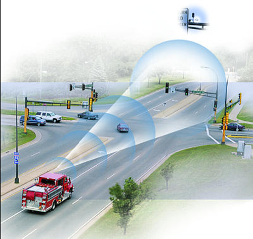
Several types of technologies are available to detect vehicles requesting preemption , and include the use of light (strobe), sound (siren), pavement loops, radio transmission, and push buttons approaching an intersection, to request immediate service (green indication from the signal). Figure 9-1 shows an example of an emergency vehicle preemption using optical detection.
Figure 9-1 Emergency Vehicle Signal Preemption Example (2)
Preemption interrupts normal signal operations to transfer right of way to the direction of an approaching emergency vehicle, but a green indication is not always guaranteed immediately after preemption is requested. The MUTCD states that the shortening or omission of any pedestrian walk interval and/or pedestrian change interval shall be permitted. This is often necessary with intersections adjacent to rail as it is often infeasible to provide clearance given the limitations of the locations of railroad track circuits and the speed of the approaching vehicles, and sometimes due to very long crosswalks versus close detection distances.
For marine transport, the preemption would not be delayed as well for the servicing of pedestrians at such locations as drawbridge crossings. The signal preemption typically occurs not at the drawbridge itself but at a signalized intersection immediately adjacent to the drawbridge. At the intersection there may well be pedestrian signals. Whether or not the ped intervals are shortened or omitted when the drawbridge preemption occurs is a matter of engineering judgment, but the MUTCD allows the ped intervals to be shortened or omitted for any type of preemption but not for “priority control”.The immediate servicing of pre-emption requests for these transportation modes is due to the need to maintain continued flow for rail and marine mobility.
Preemption is different from signal priority, which alters the existing signal operations to shorten or extend phase time settings to allow a priority vehicle to pass through an intersection. Traffic signal priority is discussed in greater detail in Section 9.2 of this chapter.
9.1.2 Effect on Signal Timing
Preemptive control has a profound affect on signal timing because, in the controller, it totally replaces normal timing and logic with preemptive timing and logic to serve a specific vehicle type. The preemptive systems can extend the green time on an approach up to a preemptive maximum, that is irrespective of the maximum green or coordination settings. Preemptive service is followed by a recovery or transition period where the controller transitions to normal signal operations and coordination timing plans (if applicable).
On a signal preemptive system in the Washington, DC, metropolitan area, once a signal was preempted, the coordinated systems took anywhere between 30 seconds to 7 minutes to recover to base time coordination(3). Signal phase sequencing and methodology for recovery or transition should be developed to minimize the impact preemption has on traffic operations and safety.
Part 4 of the MUTCD calls out the standards for how to transition into and out of preemption. The key signal timing aspects of preemption are listed here.
- Transition Into Preemption
- The yellow and all-red vehicle clearance interval shall not be shortened or omitted.
- Pedestrian walk or clearance intervals may be shortened or omitted.
- A return to the previous steady green signal indication shall be permitted following a steady yellow signal indication in the same signal face, omitting the red clearance interval.
- Transition out of Preemption
- The yellow and all-red vehicle clearance interval of the preempted approach shall not be shortened or omitted.
- A signal indication sequence from a steady yellow signal indication to a steady green signal indication shall not be permitted.
In addition, traffic signals that can receive multiple requests for signal preemption should prioritize the requests by importance of vehicle right of way and/or by difficulty in stopping the type or class of vehicle. The amount of time a signal has to transition into preemption is predicated on the distance upstream where the preempting vehicle can be detected.
Some of the benefits associated with traffic signal preemption are:
- Improved response time/travel times for emergency, rail, waterway, and other preempting vehicles.
- Improved safety and reliability for vehicles receiving preemption right of way (e.g. emergency vehicles, trains, and boats).
- Improved safety and clarity of right of way for other roadway users (i.e. avoids drivers having to yield right-of-way on their own without prompting from traffic control for an emergency vehicle or etc.).
The nature of signal preemption varies greatly in its application, e.g. heavy rail crossings near a signalized intersection must be approached differently than providing preemption for emergency vehicles. Further references should be consulted beyond the general overview presented here to fully understand the various complexities associated with signal preemption. Two such resources are the National Cooperative Highway Research Program (NCHRP) Report 3-66, Traffic Signal State Transition Logic Using Enhanced Sensor Information, which describes preemption and advanced preemption due to heavy rail and light rail vehicles (4), and Traffic Signal Preemption for Emergency Vehicles, A Cross-Cutting Study by the Federal Highway Administration (FHWA) and the National Highway Traffic Safety Administration (5).
9.1.3 Example Applications
Examples of preemptive control vary widely, but could include the following:
- The prompt display of green signal indications at signalized locations ahead of fire vehicles and other official emergency vehicles (many cities have determined that law enforcement and ambulances are nimble enough to use their siren and can navigate efficiently without the aid of signal preemption, which reduces disruption to the signals and reserves the preemption for first repsonders from the fire department);
- A special sequence of signal phases and timing to provide additional clearance time for vehicles to clear the tracks prior to the arrival of a train;
- A special sequence of signal phases to display a red indication to prohibit movements turning toward the tracks during the approach or passage of a train or transit vehicle; and
- The prompt display of green signal indications at a freeway ramp meters to progress a standing queue through the meter to avoid queue spillback into upstream traffic signals.
Various challenges are identified in these applications originating from lessons learned. These include the following:
- Typically, a signal cycles a number of times before it returns to normal timing plan operations after a preemption call is carried out. This causes less-than-optimum timing splits, offsets, and corridor progression, which results in additional delays and queues, particularly during peak traffic volume periods.
- Delays to roadway traffic can be exacerbated if preemption is used for a transit service on light rail lines especially during peak hours when frequent calls for preemption would be issued at rail crossings (6). Furthermore, rail crossing gates that provide clearance for rail vehicles requesting preemption may be held down for too long, causing further delays to roadway traffic (6). This can occur if sensor equipment, detecting the rail vehicle, is not placed in the correct locations or is not operating reliabily (6).
- Preemption can significantly shorten pedestrian walk and flash don’t walk intervals. Care should be given to allow as much time as possible to ensure safe pedestrian crossing or return to curb.
- Preempt trap at signalized intersections near railroad crossings can occur if insufficient track clearance green time is allotted in association with an advanced preemption. The track clearance green time allows vehicles in a queue to be served on the near-side approach and to clear the railroad track area. The potential problem occurs when the clearance green time is not long enough to clear the queue. Under this scenario, a vehicle could be trapped on the tracks when the railroad crossing lights come on and the railroad gates come down.
- Pre-emption calls for rail transit systems can delay emergency vehicles, thus creating a significant “public safety concern” (6). Also, if “preempt confirmatory lights” do not provide clear indications on whether an approaching vehicle has control of the signal, emergency vehicles may wrongly assume they have received preemption. This can create a potential hazard if the preemption call was issued to the rail system that is in conflict with the emergency vehicle’s approach.
- If there are multiple vendors supporting a preemption system, then interoperability will likely be required among the various proprietary technologies (e.g., between the signal controller hardware of vendor A and the traffic control software of vendor B). Such integration can be especially difficult to achieve if the vendors are market competitors (6).
- Implementing a successful signal preemption for rail is likely to require a multifaceted, coordinated systems level approach:
- Requires coordination among multiple stakeholders such as transit authorities, emergency responders, roadway agencies to minimize any adverse impacts from preemption system on each stakeholder’s operations.
- The preemption system at a particular intersection must not only take into account standard roadway traffic characteristics, but also various attributes of the transit system that it’s servicing such as headways and frequency of service. Overall, potential impacts to all relevant modes should be accounted for when designing and implementing a preemption system. It may require further analysis to comprehensively assess the impacts of signal preemption and to better understand the interaction between “rail and traffic signalizing systems” (6)
9.2 TRAFFIC SIGNAL PRIORITY
9.1.4 Traffic Signal Priority Overview
Transit Signal Priority (TSP) is an operational strategy that is applied to reduce the delay transit vehicles experience at traffic signals. TSP involves communication between buses and traffic signals so that a signal can alter its timing to give priority to transit operations. Priority may be accomplished through a number of methods, such as extending greens on identified phases, altering phase sequences, and including special phases without interrupting the coordination of green lights between adjacent intersections. Ultimately, TSP has the potential to improve transit reliability, efficiency, and mobility.
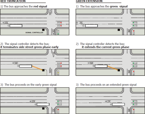
With TSP, there are two basic methods to adjust the signal timing at an intersection for an approaching bus: reducing the red time (red truncation) or extending the green time (green extension). Figure 9-2 illustrates these methods.
Figure 9-2 Effect of TSP to Adjust Signal Timing
Differences from signal preemption
TSP is different from signal preemption, which interrupts the normal signal cycle to accommodate special events (e.g., a train approaching a railroad grade crossing adjacent to a signal or an emergency vehicle responding to a call). For example, a fire engine may send a preemption request that instantly alters the traffic signal timing and or phasing to provide a green indication. In this case, the normal signal operations process would be disrupted. More specifically, with pre-emption certain phases may be skipped or replaced for approaches to the intersection that are not receiving the signal pre-emption treatment (7). Note: preemption is discussed in Section 9.1.
With TSP, however, the transit detection system communicates a priority request to the traffic signal that may or may not be granted. If such a request is granted, the traffic signal timing is altered to serve the priority request without disrupting coordination. In this situation, the normal signal operations process and overall signal cycle are maintained (6). With TSP, side-street phases would not be skipped, although the timing of these phases is likely to be altered.
To achieve greater uniformity in the deployment and implementation of ITS and applications such as TSP, a “family” of communication standards was developed known as The National Transportation Communications for ITS Protocol (NTCIP) (6). NTCIP 1211 was established by the Signal Control and Prioritization (SCP) working group, and it provides a set of communication standards for exchanging information among SCP systems such as TSP.
NTCIP 1211 represents the physical elements needed to provide signal priority, typically four components associated with the bus detection system and the traffic signal controller. The detection system lets the TSP system know where the vehicle requesting priority is located. The detection system communicates that message with the priority request generator (PRG) and the priority request server (PRS) manages those requests. The fourth and final component of the system may be the transit AVL or traffic management center which monitors the system and logs data.
9.1.5 Effect on Signal Timing
Transit signal priority has a limited affect on signal timing because it adjusts to normal timing and logic to serve a specific vehicle type. The priority algorithm modifies the green allocation and may work within the constraints of coordination settings or maximum green. The NTCIP 1211 standard requires that priority allow the coordination logic to be maintained without a recovery or transition period after the priority request.
The most commonly reported benefits of using signal priority include reduced signal delay for transit vehicles and improved transit travel time. In some cases, improved reliability has been provided through the integration of a transit system’s Automatic Vehicle Location (AVL) system to request priority only when the vehicle is behind schedule.
9.1.6 Examples of Transit Signal Priority
TSP has been employed in various urban transit networks throughout the United States. King County, Washington, which includes the Seattle metropolitan area, is one region where TSP is actively operating. Portland, Oregon, is another. While both of these systems ultimately alter the timing of traffic signals to provide some benefit to transit vehicles, they differ in the way signal priority requests are generated.
King County, WA
With the TSP system for King County Metro, the transit vehicle is not responsible for generating a NTCIP 1211 standard priority request for signal priority. Instead, the vehicle only communicates its presence to the traffic signal system, which in turn has the ability to generate a signal priority request for the approaching bus.
As the vehicle approaches an intersection, an Automated Vehicle Identification (AVI) system within the bus transmits information, such as a vehicle’s ID number, to a roadside reader. The reader detects the presence of a transit vehicle approaching the intersection and sends a message to a transit interface unit located in the individual signal controller cabinet.
TSP has resulted in transit performance improvements in King County. For example, the combination of TSP and signal optimization is responsible for a 40% reduction in transit signal delay along two transit corridors. Another one of the observed benefits from TSP in King County was a 35–40% reduction in travel time variability (7).
Portland, OR
In contrast with the TSP system in King County, transit vehicles in Portland, Oregon have the ability to decide whether or not to request priority through the AVL integration described above. . The vehicle is equipped with detection equipment (optical-based) similar to that used to provide an emergency vehicle with a preemption request. Unlike preemption, however, the transit vehicle using ITS only transmits input to the signal control system when it needs priority, such as when it is behind schedule. This process generally results in “first in, first out” operation, where the first vehicle to transmit a need for priority is served first, regardless of relative need.
Like King County, transit vehicles in Portland have experienced some measurable benefits with the TSP implementation. Some of those benefits are a 10% improvement in travel time and a 19% reduction in travel time variability. With the increased reliability, less schedule recovery time was needed to keep the buses on schedule. Moreover, the benefits of TSP enabled the Portland transit agency, TRIMET, to avoid having to purchase an additional bus (7).
9.3 TRAFFIC RESPONSIVE OPERATION
9.1.7 Traffic Responsive Overview
It is common for a coordinated traffic signal to operate different timing plans at different times of the day and days of the week. This is done by utlizing a predetermined timing plan that best suits the current traffic conditions. For example, at different times, a signal may operate an a.m. Peak, a p.m. Peak, or an Off Peak plan. It may also operate in free (uncoordinated) mode at other various times, such as overnight. The most common means of determining when to change timing plans is to use a time-of-day and day-of-week schedule. This is referred to as time-of-day (TOD) plan selection and is described in more detail in Chapter 7. The time-of-day plan selection schedule can be implemented in either the controller, field master, or a central computer system. However, during incidents or other unusual conditions, plans may also be changed manually through the same means. In any case, signal coordination usually requires that the timing plan be changed simultaneously at all signals within a coordinated group. Therefore, if time-of-day plan selection is done locally at the controller, all controllers within a coordinated group need to be configured with the same time-of-day schedule.
Time-of-day plan selection works well when traffic conditions are consistent and predictable – that is, similar traffic patterns generally occur during the same times each day. When an incident, a planned event (e.g., construction, county fair, football game, etc.), extreme weather, or any other unusual occurrence causes a significant change in the normal traffic conditions, the timing plan selected by the time-of-day method may not be the plan best suited to current conditions. To address this situation, the traffic responsive plan selection method uses data from traffic detectors, rather than time of day, to automatically select the timing plan best suited to current conditions.
Plan selection for responsive operations may also be invoked manually. There are several instances where agencies operating traffic signals from their traffic management centers will use predetermined plans for planned special events or recurring congestion on an as needed basis.
To implement traffic responsive operations, it may be necessary to update TOD/coordination plans. Along with fine tuned plans, it is critical to confirm that the local controller clocks are in sync to maintain the coordination plans.
9.1.8 Techniques - Operational
Traffic responsive plan selection (TRPS) normally takes place in a field master or a central computer system. When the master or computer selects a new timing plan, it sends a command to all signals in a coordinated group to instruct them to change to the new plan simultaneously, thus ensuring coordination is maintained.
The master or central computer monitors volume and/or occupancy data from multiple vehicle detectors. The data from the detectors are weighted, merged, and otherwise processed to calculate values for a few key parameters that are compared to thresholds. When a threshold is crossed, one of the predetermined plans is implemented for the conditions represented by the threshold categories selected. Different signal system suppliers use different parameters and algorithms for traffic responsive plan selection. A user needs to refer to documentation specific to their signal system and must prepare these in advance. Most algorithms involve separate calculations and threshold comparisons for each cycle length (total volume of traffic), offset (direction of traffic with largest volume), and split (relative occupancy and/or volume on different streets).
Regardless of the algorithm used, traffic responsive plan selection requires the user to enter potentially complex configuration parameters. When setting up TRPS, considerable effort may be needed to identify the vehicle detectors that will provide an adequate representation of traffic conditions, to establish appropriate parameter values associated with those detectors, to establish appropriate thresholds and associated plans, and to fine tune the configuration based on its performance once TRPS is implemented. Historical traffic count (and preferably occupancy) data should be available for candidate detectors before the detector selection and setup process begins. It is often necessary to repeatedly adjust parameters, especially thresholds, based on observation of calculated values relative to actual traffic conditions until effective settings are established.8
The detectors used in TRPS generally need to be located away from the stop line. (Advance detectors or departure-side detectors are commonly used.) The detectors need to be configured so that the controller can generate reasonably accurate count and occupancy data separately for each direction of travel even if served by the same signal phase, and preferably for each lane. Such detectors are often referred to as system detectors. Detectors used in TRPS must be actively monitored, reliable and faults must be repaired quickly.
If the volume of traffic trying to make a movement at an intersection exceeds the capacity of the traffic signal’s phase serving that movement, traffic queues can grow over multiple cycles. In this case, measuring the volume of traffic served by the phase will not detect the overload condition. Occupancy (temporal density, or the portion of time that a detector is occupied, in the range 0.00 to 1.00) on an advance detector within the queuing area can be used to detect the onset of additional queuing, even though the served volume doesn’t change. Occupancy can therefore be used to select a plan with a cycle length and split that will accommodate the excess traffic demand. On the other hand occupancy alone is relatively insensitive to traffic volume changes under free flow conditions, when queues don’t extend onto detectors.
Algorithms usually allow the use of a combination of volume and occupancy in plan selection. One technique is to combine these into a single dimensionless value by summing the volume (count) and a multiple of the occupancy. This process is often referred to by the expression Volume (V) + Factor (k) x Occupancy (O), or V+kO. Increasing the value of the factor k increases the sensitivity to occupancy changes, relative to volume.
The algorithms commonly used in TRPS include hysteresis to prevent oscillations across a threshold. Even so, it is common for timing plans to change too frequently, resulting in inefficiencies due to offset transitions. On the other hand, the time period over which selection values are calculated can result in a coordinated system being too slow to change plans at the onset of a rapid change in traffic volumes such as may result from a major incident. Nonetheless, when well configured and fine tuned, TRPS can result in improved traffic signal operation compared to time-of-day plan selection, especially for coordinated signal groups subject to significant unpredictable changes in traffic flows. A related problem is that the plan change may occur during peak traffic conditions when an offset transition has a greater negative impact.
Despite the problems sometimes encountered, a well configured and fine tuned traffic responsive plan selection process can result in improved traffic signal operation compared to time-of-day plan selection for coordinated signal groups subject to significant unpredictable changes in traffic flows. Such conditions are often found, for example, adjacent to a major event venue and on a route that serves as a by-pass for a blocked freeway segment.
If the actual traffic conditions are quite different from that for which any of the available plans was designed, as often happens during both planned and unplanned events, it may be necessary to develop special timing plans for unusual conditions. For example, a special plan may be designed to serve extra heavy traffic (in one direction) leaving a sporting event or bypassing a freeway blockage. Traffic responsive plan selection can automatically implement such a plan when those conditions occur.
TRPS merely selects a timing plan to operate, but does not make changes to the timings specified in the timing plan. That is the role of adaptive traffic signal control, described in Section 9.5.
9.4 ADAPTIVE TRAFFIC SIGNAL CONTROL
9.1.9 Adaptive Traffic Signal Control Overview
Adaptive traffic signal control is a concept where vehicular traffic in a network is detected at an upstream and/or downstream point and an algorithm is used to predict when and where the traffic will be 9-8 and to make signal adjustments at the downstream intersections based on those predictions. The signal controller utilizes these algorithms to compute optimal signal timings based on detected traffic volume and simultaneously implement the timings in real-time. This real-time optimization allows a signal network to react to volume variations, which results in reduced vehicle delay, shorter queues, and decreased travel times.
All adaptive systems are critically linked to good detection systems. While some adaptive systems will have better tolerance of detector faults than others, the reliability and accuracy of the decisions made by the adaptive algorithms cannot be achieved without well-maintained detection. While it is important to consider maintenance of detector systems for all types of traffic signal control, maintenance of detection for adaptive systems is particularly important.
Adaptive signal control autonomously adjusts signal timing parameters in real-time, to respond to actual, real-time traffic conditions. By adjusting the traffic control parameters to more closely align with traffic conditions, adaptive systems can reduce traffic delay, increase average speeds, improve travel times, and decrease travel time variability. Many studies have shown that adaptive signal control improves average performance metrics by 10%, with some systems improving particularly poor conditions by 50% or more. In some cases, comparisons suggest that adaptive systems do not improve traffic conditions significantly. These studies have typically compared adaptive control with “well-tuned” actuated and pre-timed systems. Thus, good and sound signal timing practices, such as those promoted in this manual, can go a long way to improve traffic conditions. However, adaptive systems can still have a profound impact even starting from well-designed baseline signal timings where:
- Traffic conditions fluctuate randomly on a day-to-day basis
- Traffic conditions change rapidly due to new or changing developments in land use
- Incidents, crashes, or other events result in unexpected changes to traffic demand
- Other disruptive events, such as preemption, require a response
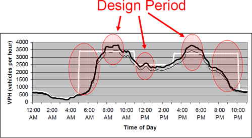
The underlying reason for adaptive system performance is quite simple; when system conditions are stable, there is little need to modify the control parameters if they are set appropriately. In the situation where fixed parameters have not been chosen by thorough analysis, adaptive systems can find better traffic control parameters. When system conditions change, system performance can only be improved by modifying the control parameters. As shown in Figure 9-3, a typical signal timing time-of-day plan schedule can be adequate for a majority of daily volume fluctuations, but may not be optimal under variable flow.
Figure 9-3 Sample Time of Day Volume Profile Compared to Time of Day Timing Schedule
In addition, where congestion is high, adaptive systems typically provide benefits above fixed-time and fixed-parameter systems by:
- Delaying the onset of oversaturation
- Recovering more quickly from saturation after traffic demand has dissipated
On the other hand, there are cases where fixed-time and fixed-parameter systems may outperform adaptive control approaches when traffic volumes are very low. In this case, sound traffic engineering practice is adequate for effective traffic management.
9.1.10 Adaptive Control Concepts
Many adaptive systems have been developed over the last 30 years. New systems continue to evolve and new techniques have emerged as technology and traffic control system architectures have taken shape. In the United States, there are several adaptive systems available from a variety of vendors.
All adaptive control systems are driven by a similar conceptual process:
- Collect data in real-time from sensor systems to identify traffic conditions
- Evaluate alternative signal timing strategies on a model of traffic behavior
- Implement the “best” strategy according to some performance metric
- Repeat steps 1,2,3 again and again
Each adaptive system is distinguished by how it uses different components or approaches to these four key steps in the control of the traffic system.
All adaptive systems need accurate and comprehensive traffic detection systems, but some need a particular size or length or placement of detectors, while others are more flexible. Most adaptive systems require more detection than would be deployed for semi-actuated traffic control and traffic responsive plan selection methods.
Most adaptive traffic systems use some form of a traffic model to evaluate alternative traffic control strategies. This model may be based on virtually moving individual vehicles down the street and predicting their movements, estimating platoons of vehicles, measuring statistics of occupancy or volumes over time, and other approaches. All adaptive systems must have some way of internally evaluating the question: “Is traffic control scheme A better or worse than control scheme B? (and C and D and E …)”. To some extent, all adaptive systems:
- Represent the current state of the traffic system
- Predict how the conditions of the traffic system will change if the control strategy changes (as well as what will happen if it doesn’t) through various algorithms
Based on the complexity of the traffic model, the adaptive control system ranges from thousands of parameters (based on the number of intersections of the deployment) to very few. In most cases, parameters require calibration and adjustment. This can be a time-consuming and expert-driven process during deployment. The better tuned the traffic model becomes (i.e. the more it is matched to what is happening in the real-world), the better the system will perform. Some systems can automatically adjust their internal model parameters and others require human judgment and interaction. In any event, the traffic model and the prediction methodology (and how accurate its predictions are with respect to what really happened) used by the adaptive system determine how effectively it operates.
Finally, all adaptive systems evaluate alternative traffic control strategies and pick the best alternative according to a performance metric. There are three components to this element of adaptive control:
- The process for searching through as many possible alternatives as quickly as possible
- Evaluating each alternative using a performance metric
- Trading off improvements at individual intersections with system-wide performance considerations
The search methodology itself is not typically important for signal timing, but how the traffic engineer is able to constrain or influence the search of alternative timing strategies is critical to the success of adaptive system deployment. For example:
- The minimum and maximum phase lengths
- Which phase sequences are allowed or disallowed
- How rapidly or slowly the system allows timing parameter changes
Other parameters, specific to individual adaptive systems, are key elements to guide the adaptive system in searching appropriate and effective signal timing strategies. Training and staffing are important to keep the system operating at its best.
Similar to the process to identify constraints for signal timing optimization, the influence of the traffic engineer in determining the performance metric is also critical to the success of the adaptive system. Typical performance metrics may be to minimize total intersection delay, or some weighted combination of intersection delay and stops. Other systems look at different metrics such as progression efficiency, or maximizing a green-band along an arterial. Whatever the metric is in the adaptive system, the traffic engineer must ensure that the metric matches what he or she envisions as the proper optimization objective for the traffic where the adaptive system is deployed.
9.1.11 Examples of Adaptive Traffic Control Systems
In the United States, many adaptive control systems have been deployed, but adaptive systems still control less than 1% of all the traffic signals in the nation. As detection and communications technology improves, adaptive systems are certainly becoming more popular and effective. This section provides a brief description of some systems that have been deployed in the U.S. over the last 20 years.
Split Cycle Offset Optimisation Technique (SCOOT)
Developed in the United Kingdom, SCOOT is the most widel deployed adaptive system in existence. SCOOT uses both stop-line and advance detectors, typically 150-1,000 feet (50-300 meters) upstream of the stop line (or exit loops (loop detectors located downstream of the intersection), measuring vehicles leaving the upstream detector). The advance detectors provide a count of the vehicles approaching at each junction. This gives the system a high-resolution picture of traffic flows and a count of the number of vehicles in each queue, several seconds before they touch the stop line (allowing time for communication between the traffic signal controller and the central SCOOT computer). SCOOT also provides queue length detection and estimation. Under the SCOOT system, green waves can be dynamically delayed on a "just in time" basis based on the arrival of vehicles at the upstream detector, which allows extra time to be allocated to the previous green phase, where warranted by heavy traffic conditions. SCOOT controls the exact green time of every phase on a traffic controller by sending “hold” and “force-off” commands to the controller.
The SCOOT model utilizes three optimizers: splits, offsets, and cycle. At every junction and for every phase, the split optimizer will make a decision as to whether to make the change earlier, later, or as due, prior to the phase change. The split optimizer implements the decision, which affects the phase change time by only a few seconds to minimize the degree of saturation for the approaches to the intersection.
During a predetermined phase in each cycle, and for every junction in the system, the offset optimizer makes a decision to alter, all the offsets by a fixed amount. The offset optimizer uses information stored in cyclic flow profiles and compares the sum of the performance measures on all the adjacent links for the scheduled offset and the possible changed offsets.
A SCOOT system is split into cycle time “regions” that have pre-determined minimum and maximum cycle times. The cycle optimizer can vary the cycle time of each REGION in small intervals in an attempt to ensure that the most heavily loaded NODE in the system is operating at 90% saturation. If all stop bars are operating at less than 90% saturation, then the cycle optimizer will make incremental reductions in cycle time.
Sydney Co-ordinated Adaptive Traffic System (SCATS)
Developed in Australia, SCATS uses a split plan selection technique to match traffic patterns to a library of signal timing plans and scales those split plans over a range of cycle times. SCATS gathers data on traffic flows in real-time at each intersection. This data is fed to a central computer via the traffic control signal. The computer makes incremental adjustments to signal timing based on second by second changes in traffic flow at each intersection. SCATS performs a vehicle count at each stop line and measures the gap between vehicles as they pass through each junction. As the gap between vehicles increases, green time efficiency for the approach decreases, and SCATS seeks to reallocate green time to the greatest demand. SCATS selects a timing plan on the controller, and thus the local actuated controller uses its own inherent gap-out and force-off logic to control the intersection second-by-second.
Real Time Hierarchical Optimized Distributed Effective System (RHODES)
RHODES uses a peer-to-peer communications approach to communicate traffic volumes from one intersection to another in real-time. By passing the data back and forth over a high-speed communication network, RHODES is able to predict the impacts of traffic arriving 45-60 seconds upstream and plan for traffic phase sequence and phase durations accordingly. RHODES continually re-solves its planned phase timings, every 5 seconds, to adapt to the most recent information. RHODES requires upstream and stop-bar detectors for each approach to the intersections in the network and has a wide variety of parameters that are used to calibrate the traffic model to real-world conditions. RHODES over-rides the local controller by sending “hold” and “force-off” commands to the controller to set the exact duration of each phase.
Optimized Policies for Adaptive Control (OPAC) “Virtual Fixed Cycle”
The OPAC adaptive control system uses a predictive optimization with a rolling horizon. This congestion control strategy, which attempts to maximize throughput, adjusts splits, offsets, and cycle length, but maintains the specified phase order. For un-congested networks, OPAC uses a local level of control (at the intersection) to determine the phase durations, and a network level of control for synchronization which is provided either by fixed-time plans (obtained offline), or by a virtual cycle (determined online). The levels of local and global influence are flexible and can be adjusted by the traffic engineer. The state of the system is predicated using detectors located approximately 10-15 seconds upstream on the approaches to the intersection. OPAC sends “hold” and “force off” commands to the local controller to set the exact duration of every phase on the signal.
Adaptive Control Software Lite (ACS-Lite)
ACS-Lite was developed to reduce the costs to deploy adaptive control systems, by consolidating the adaptive processing into a master control unit that supervises local field controllers. ACS-Lite downloads new split, offset, and cycle parameters to the local controllers every 5-15 minutes in response to changing traffic conditions. ACS-Lite is based on a very simple traffic model that has very few tunable parameters and requires modest calibration. Of all actuated systems, ACS-Lite may be the slowest to respond to rapid changes in traffic flows. ACS-Lite sends cycle, offset, and split values to the local controller. The gap-out and force-off logic of the controller works normally with the updated parameters.
9.5 PLANNED SPECIAL EVENTS, INCIDENT, & EMERGENCY MANAGEMENT
9.1.12 Overview
Signal timing can play a role in managing and even mitigating certain types of non-recurring congestion. In particular, high volumes of traffic generated by planned special events, reduced corridor capacity from roadway incidents, or increased travel demand triggered by region-wide evacuations can necessitate signal timing changes. A primary goal of readjusting signal timing in these circumstances would be to give priority to specified movements and to minimize the overall delay experienced by users from the non-recurring congestion. One way to achieve this objective would be to sustain and/or increase the throughput of traffic at certain intersections by increasing the green time for those movements. Traffic signals with modified timing settings perform this function by essentially “flushing” the preferred movement.
While increasing the roadway throughput, signal timing can also help to sustain or increase corridor capacity during an event. For example, during an evacuation from a hurricane, longer green times at signal lights for the preferred movement could enable an arterial to serve greater traffic volumes per hour.
Signal timing is modified during these events to meet other objectives besides those related to traffic operations and arterial performance, such as enhancing public safety. Traffic lights, for example, operating with these modified settings could reduce delays for emergency responders traveling to an incident on the roadway (9).
Another goal of changing signal timing would be to guide motorists to a certain destination, which could be the venue for a planned special event or the destination for evacuated traffic. More specifically, with certain roadways providing greater capacity or increasing traffic flow from the modified signal timing settings, motorists are “attracted” to these less-delayed corridors. In turn, these corridors become a pre-designated route for the traffic of a special event or roadway incident.
9.1.13 Techniques – Operational
The techniques to modify signal timing during special events, roadway incidents, or evacuations involve processes in traffic operations and planning, and some management and coordination at the policy and institutional levels. On the operations/planning side, an initial step would be to determine the specific route and intersections where traffic signals would be retimed. This route could be a particular arterial that is parallel to a certain freeway. In the event of an incident on the freeway, traffic could be diverted from the freeway to this arterial, which could provide additional capacity for a preferred movement with the modified timing settings in place at its various traffic signals.
Before signal timing is changed in response to certain non-recurring traffic, field observations or collected data would need to be collected before and during the event to determine whether such adjustments are warranted. This data may include traffic volumes/speeds and other traffic flow characteristics to detect the occurrence of a roadway incident or the presence of special event traffic. In
one example, video cameras placed along certain arterials could help to verify whether an accident is causing non-recurring congestion. In another example, sensors placed at the ingress/egress points of various parking garages could determine when motorists are leaving a special event (such as a basketball game). These devices could indicate when to activate special signal timing plans.
Once the non-recurring traffic is detected, a particular change to the signal timing settings may be to increase green time for preferred or diverted movements. Meanwhile, the signal timing for the other movements remains the same. This results in an increased cycle length.
After making such adjustments, “real-time” monitoring would be required to ensure a more rapid implementation of appropriate timing plans and to permit operator manual control as needed (9).
9.1.14 Policy/Institutional Strategies
These operational procedures may not be effective or possible without a sufficient level of coordination among the jurisdictions impacted by the traffic from special events or emergency situations. This inter-jurisdictional coordination is needed among such institutions as law enforcement, public safety organizations, and various transportation/transit agencies to share resources, seamlessly exchange the required information, and to implement the required traffic control/signal timing plans (10). Overall, adjusting signal timing can reduce delays for motorists during special events, roadway incidents, or evacuations.
9.1.15 Example Implementations
Coordinated Highways Action Response Team (CHART) – State of Maryland
CHART is a cooperative group between the Maryland Department of Transportation, Maryland Transportation Authority, and Maryland State Police with several other federal and local agencies. This group started in the mid-1980s and focused on improving travel to and from the eastern shore, but has developed into a multi-jursidictional and multi-discplinary program ranging from Baltimore to the greater Washington D.C. area.
As part of the CHART system, many of the area highways are monitored via system detectors, video cameras, a cellular phone system, and weather sensors. Once an incident is detected, information is provided to the stakeholders and users. The stakeholders determine what is needed to mitigate the incident, perhaps a tow truck or lane closure. The user is informed of alternate routes or notified to expect delays. It is estimated that the program results in a total delay time reduction of almost 30 million vehicle-hours, and a total fuel consumption reduction of approximately 5 million gallons (11)
The incident detection is integrated with the signal system software and allows pre-set signal timing plans to be implemented when needed. The system is developed so that when a change occurs in the traffic conditions on the highway, a message is given to various stakeholders. Then the stakeholders will decide if a diversion and a change of signal timing is needed for adjacent arterials.
City of Portland
The City of Portland, in conjuction with the Oregon Department of Transportation and Multnomah County, has developed various incident management plans along Interstates 5 and 205. A key to the plan is detection of incidents on the highway system. Upon detection—either by video, system loop detectors, or visual—dynamic message boards are programmed to inform motorists of the incident and possible diversion. If there is a diversion, the signal timing along adjacents arterial is modified to accommodate the influx of volume.
9.6 WEATHER-RELATED FACTORS THAT INFLUENCE SIGNAL TIMING
9.1.16 Weather-Related Factors Overview
Traffic signals are exposed to a range of weather conditions that may influence how users move through the intersection. Depending on the region, these conditions can include heavy rain, thunderstorms, slush, ice, and even snow. Fog is another weather-related factor that can reduce visibility and make it more difficult for drivers to see an approaching intersection. There are also cases of extreme weather disturbances such as hurricanes, tornadoes, and blizzards that may necessitate changes in signal timing at the effected intersections.
9.1.17 Techniques – Operational
Any of these above conditions or extreme incidents could warrant a change in signal timing settings. For example, fog could reduce visibility to the point of lowering intersection approach speeds. Inclement weather can also lead to increasing headways between vehicles and reductions in saturation flow rates through an intersection (12). In particular, roadways can become significantly congested with traffic evacuating areas impacted by such extreme weather conditions as hurricanes. At the same time, during snowy conditions roadways may be less congested, but there is likely to be an increase in start-up lost time and a reduction in tire pavement friction at an intersection.
Due to these effects on roadways and traffic patterns, modifying signal timing plans could mitigate or prevent increased delays at intersections. In particular, changing signal timing settings during inclement weather may improve the use of the traffic signal display. For example, with the increasing headways between vehicles in bad weather, phase times can be readjusted to maintain signal coordination for the traffic stream.
Another benefit can occur along roadways congested with traffic leaving a bad weather region. For example, in Clearwater, Florida, system operators have increased green times along roadways for traffic leaving the nearby beaches in the event of thunderstorms. One study has determined that this signal timing modification resulted in reduced delay at intersections and thus increased “roadway mobility” along major artierials (15).
In spite of these performance improvements, it is still uncertain whether modifying existing signal timing plans would be necessary for maintaining or improving the level of service at an intersection. Fewer vehicles on the roadway during inclement weather result in lower delays and thus the overall performance of the signalized intersection would not significantly decrease even with revised signal timing settings. Results in a few studies show that corridor operations would not be “radically affected” by bad weather, thereby making a modified signal timing plan less necessary (13).
The retiming of traffic signals in bad weather could be beneficial from a safety perspective. In particular, increasing the “amber-all-red interval” could improve drivers’ ability to either pass through or stop at the intersection safely. At the same time, changing signal timing plans during bad weather could help to reduce traffic speeds that are unsafe for the weather conditions. In Charlotte, NC, traffic signals at intersections were modified during inclement weather to operate with increased cycle lengths or with peak period timing plans. The result of these actions led to a reduction in travel speeds, and thus have “[minimized] the probability and severity of crashes” according to one study (16).
9.7 REFERENCES
- Manual on Uniform Traffic Devices for Streets and Highways (MUTCD), 2003 Edition. United States Department of Transportation, Federal Highway Administration, Washington D.C., 2003.
- #M™ Opticom™ Priority Control System, http://www.yaakoby.com/Editor/assets/mediawebserver.pdfput=html&PC_7_0_56OU_gvel=PFJZV1PKJ1gl&
PC_7_0_56OU_vroot=1PGXVVLN9Xge&PC_7_0_56OU_node=W7MPSPH3XVbe&PC_7_0_56OU_theme=tss_portal&PC_7_0_56OU_command=AbcPageHandler March 2, 2007. - Rodegerdts, Lee, Brandon Nevers, Bruce Robinson, John Ringert, Peter Koonce, Justin Bansen, Tina Nguyen, John McGill, Del Stewart, Jeff Suggett, Tim Neuman, Nick Antonucci, Kelly Hardy and Ken Courage, “Signalized Intersections: Informational Guide.” FHWA-HRT-04-091, Federal Highway Administration, Washington D.C., August 2004.
- Urbanik, Thomas, Scott Beaird, Doug Gettman, Larry Head, Darcy Bullock, Ed Smaglik, Rick Campbell, and Matt Albett, “National Cooperative Highway Research Program Project 3-66: Traffic Signal State Transition Logic Using Enhanced Sensor Information.”
- “Traffic Signal Preemption for Emergency Vehicles: A Cross-Cutting Study, Putting the "First" in First Response.” FHWA, NHTSA, Washington D.C., January 2006.
- “Review of Signal Operations in the Minneapolis Hiawatha Avenue Light Rail Corridor”, Federal Highway Administration Resource Center, November 2004.
- ITS America, Transit Signal Priority (TSP): A Planning and Implementation Handbook May 2005.
- Montasir M. Abbas, Nadeem A. Chaudhary, Anuj Sharma, Steven P. Venglar, and Roelof J. Engelbrecht. Guidelines for Determination of Optimal Traffic Responsive Plan Selection Control Parameters. Report 0-4421-1. Texas Transportation Institute, 2004.
- Managing Traffic for Planned Special Events, United States Department of Transportation, Federal Highway Administration, Washington D.C. September 2003.
- Managing Travel for Planned Special Events Fact Sheet, Report No. FHWA-OP-04-034, United States Department of Transportation, Federal Highway Administration, Washington D.C. November 2003.
- U.S. Department of Energy, Energy Information Administration, Short Term Energy Outlook – January 2002, Washington, DC: 2002, p. 23
- Al-Kaisy, Ahmed & Freedman, Zachary. November 2005. Weather Responsive Signal Timing: Practical Guidelines. Paper submitted to the Transportation Research Board 85th Annual Meeting January 22-26, 2006.
- Maki, Pamela J. 1999. Adverse Weather Traffic Signal Timing. Prepared by Short Elliott Hendrickson, Inc., for the Minnesota Department of Transportation.
- Federal Highway Adminstration, Mitretrek Systems. Best Practices for Road Weather Management. Version 2.0. City of Clearwater, Florida Weather-Related Signal Timing.
- Federal Highway Adminstration, Mitretrek Systems. Best Practices for Road Weather Management. Version 2.0. City of Charlotte, North Carolina Weather-Related Signal Timing.