Traffic Control Systems Handbook: Chapter 12. Design and Implementation

Figure 12-1. CADD Workstation and Operator.
12.1 Introduction
The material in this chapter:
- Places the system design, procurement, and installation tasks in perspective with respect to total system planning and implementation,
- Describes alternative approaches to the procurement of systems, including contractor selection,
- Describes the various elements of the design process, and
- Describes elements of an approach to manage the system installation.
12.2 System Implementation
System Design
Chapter 11 describes the system development process through the requirements step, resulting in the identification of the functional requirements for the system. The design process consists of selecting the technologies and software to implement these requirements, and to identify locations for deployment. In some cases, modifications may be required to commercially available equipment, software or to an agency's specifications.
Traffic signal control systems are usually based, in large measure, on existing software that may be provided by a number of suppliers. These software functions may be modified or augmented by the specifications resulting from the design process. The agency procuring the traffic system may also have software or equipment specifications that require consideration during the design process. The design process described below should be considered with these issues in mind.
Agencies responsible for operation of traffic control systems often have standards for commonly employed field equipment. It may be necessary for compatibility and to simplify logistics to employ these standards for new systems to the extent possible.
The USDOT ITS JPO's Standards website (www.standards.its.dot.gov) provides current status on the ITS Standards Program. It also contains resource documents, fact sheets, testing, deployment contact, training and application area information as well as an interactive ITS Standards Forum. A link is also provided to the ITS Data Registry, a growing repository of elements of the ITS Standards.
The design phase consists of two subphases, high level design and detailed design.
High Level Design
High level design provides the transition between requirements and detailed design. It includes:
- Definition of architecture.
- Sub-system definition.
- Sub-system verification plan development.
- Interface identification.
Items such as the following may be included:
- Development, evaluation and selection of alternatives. Examples include detector and communication technology.
- Identification of functions that may be unique to the system. These may include items such as:
- Surveillance and control strategies,
- Mode structures,
- Graphics,
- Controls and displays,
- Interfaces with other systems, and
- Operation with legacy field equipment.
- Identification of approximate equipment locations.
- Conduct of social, economic and environmental studies to assure compliance with federal and state regulations.
- Planning for access to utility supplied power and communication facilities that may be required.
- Assessment of detailed maintenance and operations resources that will be required.
- Definition of interfaces and protocols for data exchanges with other agencies and systems.
- Development of a plan to procure the system. This is further discussed in Section 12.3.
Detailed Design
Detailed design completes the description of the system at the component level. It includes:
- Configuration item identification,
- Component level specifications,
- Code specifications,
- Hardware specifications,
- Verification procedures,
- Software specifications,
- Intersection installation plans,
- Traffic management center installation plans, and
- Detailed cost estimates.
Detailed design results in the development of a detailed set of plans, specifications and estimates (PS&E package) suitable for procuring the system. The specifications should include project test and acceptance requirements and the accompanying payment provisions. Design plans and specifications are discussed further in Section 12.4.
12.3 Procurement Approach
The feasibility study selects a preliminary design as the most appropriate to satisfy traffic control system goals. The agency should establish the procurement approach and contracting procedures as part of or subsequent to the feasibility study. The following sections describe three possible approaches:
- Engineer (consultant) / contractor,
- Systems manager, and
- Design / build.
The first two approaches must satisfy the following principles:
- An organization separate from that supplying the hardware, bidding on the project, or installing the system must develop the specifications, and
- The procurement of all hardware items must follow competitive bid requirements.
Engineer (Consultant) / Contractor Approach
The engineer (consultant) / contractor approach represents the traditional procedure for contracting within the traffic signal system community. Agencies have procured the majority of traffic control systems using this approach. On the basis of feasibility studies and system selection, the engineer (consultant) prepares the design plans, specifications, and estimates (PS&E) for the proposed system. Either an agency employee or a consultant can serve as the engineer. The agency then issues the completed PS&E to the contractor community, and receives bids in accordance with the agency's established practice.
In this approach, the contractor bids on a single set of plans and specifications and agrees to provide a complete system, comprised of hardware and software, procured, installed, and integrated by the contractor's organization. Hardware items may be manufactured by the contractor's firm or subcontracted within the conditions imposed by the contract. The contractor also has responsibility for all systems integration tasks, documentation, and training. He may also have responsibility for system startup assistance and the development and implementation of timing plans and other database elements.
The engineer's (consultant) activities continue during system installation and may include:
- Monitoring the contractor's progress,
- Reviewing the contractor's submittals,
- Interpreting or clarifying plans and specifications,
- Inspecting the installation,
- Coordinating activities with other agencies such as utilities.
The engineer or consultant holds responsibility for the witnessing and acceptance of components, witnessing tests at all levels and accepting the entire system. The agency or its selected consultant can perform all or part of the engineer's duties.
Systems Manager Approach
The systems manager approach requires the selection of a single firm or consulting team (as systems manager) to become responsible, under an engineering services contract, for:
- System design,
- PS&E preparation,
- Systems integration,
- Documentation,
- Training,
- Management of testing, and
- Startup.
Selecting a systems manager generally follows the typical procedures for selection of an engineering consultant with negotiated cost-plus-fixed-fee contracts frequently used.
To avoid conflict of interest, the systems manager usually accepts a hardware exclusion clause which prohibits that organization from supplying any of the hardware components of the system. The system manager often provides software.
The system manager prepares the PS&E. The agency's normal bidding processes then procure the individual subsystems or services, and the systems manager subsequently oversees testing and installation of the equipment. The systems manager may also provide the integration of all hardware elements and the software to provide a total operating system.
Design / Build Approach
The design / build approach selects a single responsible entity to perform all work associated with the deployment of the traffic control system.
This procurement approach is more commonly used for large freeway based projects than for signal systems.
The public agency monitors the activity of the design / builder. The design / builder:
- Performs all design work,
- Contracts and / or constructs system elements, and
- Commissions the system and turns it over to the operating agency (1).
A feasibility study or detailed set of requirements usually forms the basis for the design build.
The design / build contract may take the form of a negotiated or cost competitive contract.
The design / build concept may not prove consistent with the procurement regulations (or the interpretation of these regulations) of the procuring agency.
After negotiation of the agreement, the design / builder completes all aspects of the project in conformance with the preliminary design. The agency and design / builder generally negotiate changes.
The design / build approach has the key attribute of complete assumption of responsibility by the design / builder. This generally allows more rapid completion because of streamlined procurement procedures and quicker resolution of problems. Also, the design / builder has an incentive to reduce its costs and risks by completing all work quickly and turning the system over to the agency. Assuming a qualified design / build team, all skills rest within the team, leading to closer coordination and cooperation.
The approach does place a burden of supervision on the agency to maintain quality. The design / builder moves at full speed and may prove reluctant to change direction, if required due to technology changes. It also may force the agency into making quick decisions.
Some local agencies such as Salem, Oregon (2) have used this approach for the design and implementation of computerized signal system projects.
When using this approach for signal systems, the responsibility for identifying and separating work efforts of the design / builder versus the operating agency, rests with the owner. Database configuration information gathering and data entry and intersection / section graphics file generation and configuration may be large areas of work effort that can lead to future contention if not assigned openly.
In December, 2002, FHWA released regulations regarding the use of design-build contracting techniques for transportation infrastructure projects that are part of the Federal-highway program (3). An AASHTO Design-Build Task Force contributed a number of recommendations regarding the program's attributes, management and organization.
12.4 Design Plans and Specifications
Construction contract documents represent tools for communication between the owner (purchaser, local government) and contractor (supplier). Properly prepared, they prevent disagreements and facilitate project completion by clearly communicating what the owner wants done and when.
The two principal elements of contract documents are plans (drawings) and specifications (4). Plans define the physical relationships of materials procured by the contract, while specifications define the quality and types of workmanship and materials. Understanding the unique role of each of these documents will produce clarity, brevity, and consistency, and avoid redundancy. Ideally, a change in requirements will not lead to inconsistencies and misinterpretations because of the failure to modify both documents.
The following sections describe typical contents of plans, specifications, and contract documents.
Design Plans
The design plans show how components of a traffic control system are constructed and installed. Table 12-1 shows the types of plans generally included.
The items in Table 12-1 provide information for the contractor and equipment supplier to prepare a project bid. The plans also serve to control the project's construction.
|
Possessed by each agency, generally provide numerous standard drawings of frequently encountered details already approved for use in situations applicable to the project
Specifications
Specifications spell out the minimum acceptable requirements for the traffic control system's equipment and materials, and how the contractor should install the system. Deficient specifications can often lead to inferior equipment and materials. When defining the minimum acceptable requirements, remember that a construction contractor will, when possible, provide the lowest cost equipment meeting these requirements.
Sources of Specifications
Specifications should reflect the system's functional requirements and equipment and, as appropriate, physical requirements and constraints.
To assure conformance with available products, agencies often adopt existing specifications proven to result in acceptable equipment and materials. Agencies often use existing specifications in their entirety or modify them to fit their particular needs.
With the proliferation of traffic control systems in the last decade or two, state, county or city ITS standard specifications may be available for use by the local municipality or its agents. With the widespread use of the internet, now one often finds these specifications at respective web sites.
Several good sources for equipment and materials specifications include:
- Federal Highway Administration (FHWA),
- Institute of Transportation Engineers (ITE),
- International Municipal Signal Association (IMSA),
- National Electrical Manufacturers Association (NEMA),
- Other cities, and
- State highway or transportation departments.
Closed versus Open Specifications
Specifications should result in high quality equipment and materials. Unless interfacing to or expanding upon legacy systems, specifications should not be written around a particular manufacturer's software, equipment or material, thus precluding competitive bids. Closed specifications, those that specify a particular manufacturer's software, equipment or material, may not meet the intent of Federal, state, or most local procurement laws, and more than likely will lead to high, non-competitive bids. Open specifications allow a number of competitive bidders on equipment and materials, usually resulting in lower bids.
If agencies do not have the right to modify their existing software, closed specifications for the modification of legacy systems may be required. Often, off-the-shelf software products, such as languages or operating systems, fall into the closed category and are often identified by name.
Standard Specifications
Standard specifications, invoked by name, number, and date become a legal part of the contract. Examples include:
- Specifications previously adopted by the city or state,
- Wire specifications available from the International Municipal Signal Association (IMSA),
- Communications cable specifications from the Rural Electrification Administration (REA), interface specifications available from the Institute of Electrical and Electronic Engineers (IEEE), Electronic Industries Association (EIA), American National Standards Institute (ANSI), National Television Standards Committee (NTSC), International Consultative Committee for Telegraphy and Telephony (CCITT), International Telecommunications Union (ITU),
- Standard specifications for materials testing available from the American Society for Testing Materials (ASTM), and
- Military specifications (MIL specs) available from the U.S. Department of Defense.
The design engineer should become familiar with standard specifications and invoke them, as appropriate.
Contract Documents
Together with design plans and specifications, contract documents form the complete legal package to which the contractor must conform. Contract documents typically contain:
- Invitation to bid,
- Instructions to bidders,
- Bid proposal,
- Bonds,
- Agreement,
- Conditions of contract, and
- Qualifications.
Invitation to Bid
An invitation to bid generally takes the form of a one page document containing a brief project summary along with bidding and construction procedures. It simply advises prospective bidders about the existence of the project and enables them to decide whether it lies within their area of capability and interest. It further directs interested contractors to the source of bid documents.
Instructions to Bidders
Instructions to bidders tell each bidder how to prepare a bid so that all bids received have equivalent format for comparison and evaluation. This document systematizes bid forms, and its contents should confine themselves to that purpose. The document deals with the issue of exclusions and substitutions by a bidder to assure comparability of bids.
Bid Proposal
A bid proposal provides a uniform format to facilitate comparison and equal consideration for contract award. The instructions tell bidders what they must do. On the bid proposal form, they respond and quote their proposed price for doing it. Bid proposals, addressed to the agency, include general statements which commit the bidder to:
- Having read the documents thoroughly, and
- Being familiar with the site and the problems associated with supplying the system as designed.
The bidder should acknowledge receipt of all issued addenda, and individuals authorized to bind the bidder must sign where indicated.
Bonds
A bond serves as a legal document which binds another party into a formal contract as security that the bidder (or contractor) will perform as agreed. The following three types of bonds see common usage:
- Bid bond-posted by the bidder to assure he / she will sign the contract if awarded; frequently amounts to about 10 percent of the base bid,
- Performance bond-posted by the successful bidder to guarantee that he / she will complete the project and not default; this bond typically amounts to the full contract price, and
- Labor and materials payment bond-posted by the successful bidder to guarantee that he / she will pay for all materials and labor and not leave the agency liable for liens against the completed system; this bond generally amounts to the full contract price.
Agreement
The agreement provides the following five elements:
- Identification of the parties (who),
- Statement (perhaps by reference to another document) of the work to be performed (what),
- Statement of the consideration (how much),
- Time of performance (when), and
- Binding signatures of parties.
The agreement is often mistakenly called the contract. Actually, the contract consists of all the contract documents, while the agreement represents only one of those documents.
Conditions
The general conditions document serves as the fine print defining contractual relationships and procedures relative to the project. Most city and state agencies have established general conditions which apply to all their construction documents. The National Society of Professional Engineers (NSPE) (5) also publishes applicable general conditions. Agencies normally print general conditions in large quantities and issue them as standard documents. Since general conditions apply to typical construction projects, traffic systems usually require modifications called supplementary conditions. For example, an agency may require access to computer equipment during installation for database development.
Contractor Qualifications
Agencies typically require contractors to prequalify to receive project bid documents. This prequalification typically takes the form of a general review of submitted financial and experience data.
Traffic control systems represent specialized projects and require a level of expertise and experience not widespread within the contractor community. Therefore, some local and state agencies permit specification of required contractor technical experience. (Also, see Two-Step Procurement previously discussed.) This section of the contract documents should advise contractors on the minimum experience and qualifications necessary to submit a bid, and instruct them how to submit special qualification data for review. Many local and state agencies include a variety of pre-qualification requirements, such as:
- Conformance with the Equal Opportunity Act,
- Involvement as a percentage of the overall contract of:
- Women Business Enterprise (WBE),
- Disadvantaged Business Enterprise (DBE), and
- Minority Business Enterprise (MBE).
These requirements prove common in most local and state agencies. Certain agencies also require that the contractor have a local office.
Pre-Bid Conference
For moderate or large scale projects a pre-bid conference often becomes advisable. The pre-bid conference reviews the instructions to bidders and elements of the specifications. The conference may identify special or unusual features of the project. The pre-bid conference usually provides prospective contractors with the opportunity to ask questions or raise pertinent issues.
Precedence
A specific hierarchy of precedence defines and clearly establishes which document governs in case of conflict within the documents. An example hierarchy (in decreasing order of control) follows:
- Agreement,
- Plans,
- Special provisions (technical specifications),
- Standard specifications,
- Supplementary conditions, and
- General conditions.
Technical Specifications
Technical specifications outline the specific requirements for materials, equipment, installation and operation. These specifications, an integral part of the contract documents, should include individual specifications for major items of material and equipment, and methods of construction and installation. They should also include items such as operating manuals, training and software. All mandatory specification must contain the word Shall in its structure. Avoid the use of qualitative phrases such as: high performance, high availability, good, "must be reliable". Use instead quantifiable descriptions such as: "The software shall be unavailable no more then 4 hours per week on continuous operation."
Technical specifications should include the following major categories:
Definition of Terms
The lead section should define words used frequently throughout the technical specifications. These definitions serve as a glossary for terms peculiar to the design plans, specifications, and other contract documents. Examples include:
- ITE-Institute of Transportation Engineers,
- Traffic signal - Any power-operated traffic control device, except a sign or flasher, which warns or directs traffic to take some specific action, and
- Signal system - Two or more signal installations operating in coordination.
Installation of Traffic Signals
The specification for the installation of traffic signals sets forth detailed requirements for installation of various material and equipment items.
Other standard specifications (e.g., drilled shaft foundations, reinforcing steel), adopted and published by the local governing authority, may cover certain items associated with the installation of traffic signals. Standard specifications for roadway construction can normally be obtained from public works departments of cities or state highway departments. A reference, noting the name of the publication and the effective date, usually covers specifications for parts of the signal system not pertaining directly to the traffic signal installation.
Table 12-2 shows the items which the traffic signal installation technical specification should include. (6)
| Name | Description |
|---|---|
| General | The items covered by the specifications, the requirement for furnishing new stock, and the procedure for the substitution of materials and equipment |
| Materials furnished by contractor | Details of what materials and equipment the contractor must furnish and what materials and equipment others must furnish |
| Power connection | Method for furnishing power from source to controller and specifications for power line |
| Conduit | Methods for installing conduit, to include conduit approved by Underwriters Laboratories, methods for joining conduit, and methods for testing the usefulness of an installed conduit |
| Wiring | Methods for wiring controller cabinet, signal heads, and pole bases |
| Grounding and bonding | Requirements for grounding and bonding signal housing, controller housing, signal common, and power service common |
| Sealing | Requirements for sealing conduit to provide continuously sealed electrical circuit |
| Concrete | Standard specifications for concrete and reinforcing steel |
| Concrete foundation for controller cabinet and signal posts | Methods and requirements for digging, placing, finishing, and backfilling concrete foundations |
| Paint and painting | Items to be painted, type of paint, number of coats, and method of painting (e.g., baked-on or sprayed) |
| Preservation of sod, shrubbery, and trees | Requirements for the replacement of damaged sod, and the protection of shrubbery and trees |
| Removal and replacement of curbs and walks | Procedure for obtaining approval to cut curbs and / or sidewalks, and the method for their replacement |
| Controller cabinet keys | Where delivered and number of each required |
The specification for installation of traffic signals can also include other items that fit particular site-specific needs.
Specifications for Materials and Equipment
Table 12-3 provides guidelines for representative portions of material and equipment specifications required by traffic signal control systems.
| Specification | Guidelines |
|---|---|
| System master | Include both field-located arterial master and central computer |
| Intersection controller | Typically Type 170, 2070, ATC, or NEMA TS2; Type 170, 270, and ATC controllers may require software specifications |
| Mast-arm pole assembly | Include mast-arm pole, base, and anchor bolts with bolt circle requirement |
| Pedestal pole assembly | Include pole, base, and anchor bolts |
| Strain Pole | Used for span-wire mounted signal heads. Include pole, base and anchor bolts. |
| Signal heads | Include housing, doors, lenses, lamps, wiring, terminal blocks, terminal compartment, and mounting attachments, but with separate specifications for pedestrian signals |
| Signal conductor | Include covering, color coding, and physical characteristics |
| Signal cable | Include insulation, physical properties, electrical properties, color coding, and fillers |
| Detectors | Include physical properties, electrical properties, environmental conditions under which equipment must operate, controls, and methods of operation. Can include traditional detection and / or image processing detectors. |
| Communication cable | Include insulation, color coding, physical properties and electrical properties |
| Field communication or controller interface equipment | Include interface standards, data rates, physical and electrical properties |
| Color graphics display | Specify parameters and methods of display |
| Printer | Type, speed, and quality |
| Video terminals | Specify sample operator screens and controls, screen size, refresh rate, and colors |
| Computer software | Provide functional specifications for control software, compilers, assemblers, utilities, and diagnostic programs |
| Television (TV) monitoring | Specify monitors, cameras, and interface protocols |
| Changeable Message Signs(CMS) | Specify type, dimensions, method of operation, and interface protocols |
| Communications equipment | Specify data modems and interface devices |
| Utility Coordination | Include names of utilities, contractor requirements for avoidance of utility disruptions, utility services (e.g., power or telephone line tie-in) to be accessed, and method for tie-in |
| Testing | Include testing levels desired (component, subsystem, system), organizations responsible for preparation and approval of test specifications, conduct of tests and acceptance of results |
| Intellectual Property Rights | Include the desired status of rights to software (computer source code ownership, rights in use) |
Software, Database, Performance and System Test
Advanced Traffic Management Systems (ATMS) offer many features, functions and alternatives not previously available. For example, systems containing a central computer and either intelligent remote communications units (for older controllers) or modern controllers (Both NEMA and programmable controllers (Types 170, 179, ATC 2070 etc., see Chapter 7) allow significant processing and decision-making to take place at the local controller while allowing system monitoring and control from a central location. Systems of this type achieve this through the functions of protocol bits and bytes and upload / download of various parameters.
Traffic signal system software may reside in the following three components:
- Server in the traffic management center
- Field master controller for those closed loop systems using this architecture
- Intersection signal controller
Manufacturers supplying NEMA controller based systems provide the software for the intersection controller and field master controller already embedded in the controller. The software is provided as part of these controllers. The TMC software maybe provided as a purchased package.
Traffic controller software for systems based on the Model 170, and ATC 2070 controllers is procured separately from field controller hardware. It is usually procured as a compatible suite with the TMC software.
Most agencies that procure traffic systems usually employ the standard software provided by suppliers with little or no modification to the basic system functions. The agency may specify certain functions such as additional or modified displays and reports, data migration to other systems, maintenance software, interfaces with off-line signal timing programs and other functions such as CCTV control.
A summary of procedures and practices for the acquisition and maintenance of software that is not a standard supplier product may be found in Reference 7.
Some available central system software provides a comprehensive database that may include:
- Traffic engineering data such as intersection layout (CAD) drawings, or
- Maintenance files of system components and equipment.
- Source code and development environment or development tools for custom software
Performance of this software varies greatly. For example, some systems allow certain of these functions to operate in real-time. The degree of integration of CCTV images with the system can vary.
Table 12-4 lists a number of representative elements. To assure accurate and reliable performance, prepare detailed system test procedures and performance requirements.
|
It usually proves important that the contractor develop detailed system test procedures for system software and database handling. The agency should review these procedures prior to performance tests to assure inclusion of appropriate types of tests and duration. It is important that these tests that verify and validate the delivered system do indeed meet the specification established for the scope of the contract. Examples include the following tests:
- Communications,
- Upload / download,
- Algorithm performance and accuracy
- Failure mode and recovery validation
- Hardware acceptance test,
- Software acceptance, and
- System acceptance.
Many of these tests would be done by the contractor as subsystem test during the development process. It is important that the result of these tests be shared with the agency. Testing of a traffic management system is not the sole responsibility of the contractor or the agency. It is very much a team effort as problems and bugs with software systems are often very hard to diagnose. The more information that is shared the easier it would be to track down and correct these problems. Tests of subsystems shall cumulate to integrated field test where all of the field elements are in place and the whole system can be tested to insure there are no compatibility problems. This is the recommended form that the Final System Acceptance test shall take.
In some cases, the traffic system implementation plan assigns development of the entire system database to the contractor, including signal timing plans and the various coefficients and parameters required for system operation. In other cases, the agency or its consultant provides this data to the contractor for entry into the system. The specifications should clearly assign these responsibilities.
12.5 Deliverable Services
With a continuing growth in the traffic control application of computers, local area networks and sophisticated electronic components, a need has developed to add a deliverable services section to the specifications. This section defines the contractor's responsibilities to provide:
- System management,
- Documentation,
- Training,
- Startup assistance,
- Warranties / Guarantees, and
- Maintenance.
This section should also identify those database preparation tasks assigned to the contractor.
The following briefly describes deliverable services:
Systems Management
Systems management includes responsibility for all project related tasks in the following areas:
- Design,
- Manufacture,
- Procurement,
- Assembly,
- Testing,
- Installation,
- Inspection (may be shared with the using or procuring agency),
- Training,
- Initial operation, and
- Initial maintenance.
The systems manager or contractor should direct, coordinate, review, monitor, and control the project to maintain a schedule for timely and adequate completion.
The specification should require submission and frequent updating of a detailed project implementation schedule.
Documentation
System documentation proves an absolute necessity for successful system operation. The specification should require documentation in sufficient detail to:
- Reflect as-built conditions, and
- Fully describe the methods of operation, maintenance, modification, and expansion of the system or any of its individual components. Any documentation related to COTS components.
Most traffic systems are usually based on a supplier's product line system, and much of the documentation reflects this situation. Descriptions of special features or functions must be added to complete the documentation.
Table 12-5 lists typical hardware documentation requirements.
| Requirement | Description |
|---|---|
| General description | General descriptions of all components comprising the system |
| Theory of operation | Detailed description of system operation, including schematics, logic, and data flow diagrams |
| Normal operating procedure | Description of the system's routine operating procedures |
| Maintenance | Copies of manufacturers' recommended procedures; preventive maintenance procedures; troubleshooting data necessary for isolation and repair of failures or malfunctions (corrective maintenance); and detailed instructions where failure to follow special procedures would result in damage to equipment or danger to operating or maintenance personnel |
| Installation | Detailed description of physical and electrical properties of the system and other pertinent information necessary for the installation and use of the equipment |
| Parts list | Listing and identification of various parts of system |
| Schematic diagrams | Complete and accurate schematics to supplement text material |
| Maps or drawings | Drawings of conduit layouts, cable diagrams, wiring lists, cabinet layouts, wiring diagrams, and schematics of all elements of the communication system |
The agency / consultant should require the right to review all documentation prior to project acceptance.
Software documentation and rights generally prove more difficult to specify and obtain. For many hardware elements, suppliers consider unique software provided in memory as proprietary. Such software, sometimes called firmware, provides all specified operational features and supports flexible operation through a wide array of user input-output options. In such cases, the user may never need access to those programs for modifications, and thus not need detailed software documentation. NEMA controllers and field masters typify such components.
In larger computer-based systems, the user may need to modify or expand the system, thus requiring access to the software. In such cases, it becomes necessary to access source programs. Further, a full complement of executive, utility, and basic library programs for the computer system must be specified, along with the system programmer's and user's manuals.
Generally speaking, the following three levels of software rights exist:
- Proprietary - The purchaser has no rights to proprietary software other than provided by license or use agreement.
- Semi-proprietary - The user (or purchaser) has no rights to semi-proprietary software unless needed assistance proves unavailable from the supplier.
- Full rights - Rights to use, modify, and transfer software are conveyed and restricted only as defined by specific agreement.
Control system specifications should specify the required level of purchaser rights so that all bidders can reflect these requirements in their proposal or bid.
With regard to when the contractor should provide documentation, typical requirements follow:
- Soon after the selection of a specific computer system and peripherals, programmer's and user's manuals for that system should become available for agency staff,
- Equipment manuals available for technician's study prior to maintenance training, should become available concurrently with the on-site delivery or storage of hardware elements,
- To facilitate maintenance, cable routing details and wiring diagrams reflecting as-built conditions should become available after installation and prior to use of those components,
- Application software documentation along with a draft system user's manual, should become available on-site prior to conducting operations training and placing any intersection under system control. Revisions of these manuals may be required to reflect changes made prior to system acceptance,
- The final payment for system installation should be withheld until delivery of acceptable final documentation, and
- Where a period of operational support is provided (see subsequent discussion), updates to final documentation should be required.
It is imperative that complete documentation be obtained. All submitted material should be closely studied and applied during initial system implementation to assure that all needed documentation exists, complete and clear to the operator.
Documentation becomes more valuable over time because, as the system ages, it experiences maintenance and modification, and personnel changes occur. Therefore, the agency must take responsibility for management and preservation of the provided documentation. Furthermore, the agency should develop a troubleshooting document(s) and tailor it for appropriate personnel such as operations and maintenance staff. Documentation may take the form of conventional manuals or reside on computer.
Most traffic control system's software documentation often reflects the supplier's most recent traffic system product - a quasi-standard product. With agency pressure, this documentation often can be made available ahead of time. Depending on the degree of documentation completeness sought and advance documentation review, the agency can consider negotiating, in advance of procurement, for more thorough documentation.
Training
Training is typically provided in the principal areas of operation, maintenance, and data base preparation. Further, such training specifically addresses the needs of each staff level:
- Management / supervisor / traffic engineer,
- System operators, and
- Maintenance technicians.
Training should provide those technical skills needed to effectively use and maintain all system features and components. In this respect, the training specified and provided should reflect the actual needs of agency personnel.
If, for example, maintenance personnel already routinely maintain microprocessor-based controller units, training should cover familiarization with the actual unit. In contrast, an agency converting from twisted wire pair to fiber optic communications should specify extensive training, perhaps even including the operation and use of test equipment.
A secondary purpose of training fosters acceptance of the new system among agency personnel. It can provide opportunities for involvement which remove those natural barriers to system acceptance.
Training may be provided at three times:
- Pre-installation,
- During installation (before use), and
- During operation.
Pre-installation training offers an early opportunity to gain skills in a non-pressured environment on subjects such as:
- Equipment configuration,
- System capabilities and features,
- Systems operation,
- Logistic support requirements,
- Programming concepts, and
- Database needs and preparation.
During the system-installation period, other opportunities for training become available. Here, maintenance personnel can be given detailed training in:
- Operation,
- Preventive maintenance, and
- Corrective maintenance (troubleshooting).
Actual hardware should remain available during this time for hands-on training.
After system acceptance and during the period of contractor operation, training may be directed toward:
- Refresher training for operations / maintenance personnel,
- Training for new personnel, or
- Additional hands-on training under operational conditions.
Regardless of when or how much system training is specified, system contractors / suppliers benefit if the user becomes knowledgeable and proficient with the system. However, formal training proves expensive-both to the contractor and user. Because of this, numerous users of successfully operating systems confirm that the best training is gained by an active, aggressive involvement with the contractor during the system's installation, checkout, and initial operation.
Startup Assistance
The period of initial system operation typically becomes a time of intense activity. Expect maintenance problems as a result of the full exercise of hardware, coupled with any remaining unfamiliarity with the system. Software bugs may surface and timing plans and database may need refinement. In addition, operator skills and routines develop day by day. During this time, the continued support of the systems manager or contractor can enhance successful operation of the system.
This continued support beyond system acceptance has been termed startup assistance and FHWA considers it an eligible item for funding. Startup assistance can include the following tasks (8):
- Provide systems engineer to assist agency operators / engineers in adapting the system to local traffic environment,
- Define and correct hardware and software deficiencies discovered through sustained operation,
- Assist in maintaining, repairing, and replacing failed system components,
- Provide on-the-job training as an extension of formal training provided earlier, and
- Prepare and provide updates to system documentation.
The startup assistance or operational support period is often included in the contract, leading to final acceptance.
Warranties / Guarantees
The specification should define the period of time after system acceptance during which the contractor guarantees work and materials. For hardware, a manufacturer may warrant the product for one year or more from the date of delivery. Problems arise when the contractor stores such items or does not use them in the system until later in the project. To avoid ambiguities, the specification should clearly require the contractor to guarantee all hardware items for some time beyond final system acceptance. Further, any remaining equipment warranties by individual hardware manufacturers should transfer to the agency.
Maintenance
The specifications should clearly spell out maintenance responsibility for hardware items. Common practice obligates the contractor to maintain equipment until system acceptance in accordance with the contract. Except for startup assistance, FHWA policy clearly defines maintenance beyond system acceptance ineligible for Federal funding. However, some agencies include a separate non-participating bid item for maintenance during an initial period of operation (possibly one year) to:
- Assure a source of maintenance during a critical time of system operation,
- Determine anticipated maintenance costs at system completion, and
- Place responsibility for maintenance on the contractor, encouraging quality construction and the choice of more reliable hardware.
Provision of spare parts and / or subsystems also proves important. Considered maintenance items, they cannot be purchased with Federal funds. However, the contract can include spare parts as non-participating bid items. This becomes particularly appropriate when the system requires custom-made subsystems. For certain components, it may prove desirable to permit future purchase at an established price within a specified time period.
System Acceptance Tests
Testing of the installed control system should precede system acceptance by the engineer. Testing proves essential when a third party installs a subsystem. The specifications should spell out methods for testing and test documentation. In general, acceptance testing consists of:
- Equipment Checkout Tests
- Each major system component should be tested on an individual basis to verify its operation. This should include diagnostic testing of each functional feature of items such as controller units and detector electronics. Components that are newly developed or modifications of previous products may require environmental testing or certification of such testing by the manufacturer.
- For large and / or expensive items (such as CMS or system software), it may prove appropriate to perform a level of testing (witnessed by the procuring agency or its consultant) prior to the items leaving the manufacturer's or system integrator's facility.
- System Electrical Tests
The specifications should require tests to determine electrical continuity. Tests should cover each conductor, including spares.
Electrical cables, wires and connection should be tested per local and the National Electrical Codes. As a minimum, DC resistance tests of each conductor and the insulation-resistance tests between conductors and between conductors and ground should be conducted.
Typical test instruments include volt-ohm-milliammeters (VOMs) and megohmmeters (meggers).
Electrical communications cable should be DC tested with respect to open circuits, short circuits, resistance, capacitance, resistance and capacitance unbalance, crosses, and insulation resistance. Signaling tests should be conducted on both copper and fiber optic communications to assure transmission quality.
Fiber optic cable and splices should be tested per ANSI / EIA standards with respect to signal levels and attenuations at various nodes and terminations. Typical test instruments include optical signal generators, optical signal level meters, and optical time domain reflectometers, all calibrated to the applicable wavelengths. - Computer Software Tests
The contractor should test and demonstrate each feature of the control system software. These test shall also demonstrate the performance envelope of the software. Demonstration of system failure mode and recovery procedure from the provided documentation must be a part of software testing. - Systems Operations Tests
The installed system should be tested to determine the total system's reliability and performance.
In advanced traffic management and traveler information systems (ATMS / ATIS), involving several integrated components, specifications should include standalone tests for each subsystem such as:- Field controller and cabinet equipment complement,
- CCTV and
- CMS.
- Manual,
- Conventional traffic-responsive,
- Time-of-day, and
- Adaptive.
Several iterations should be performed, documented appropriately, and focused on both function and reliability / integrity. Many of the system tests can be performed via simulation at the operations center prior to actual implementation. The communications system should be tested separately and certain communications tests should be performed for longer periods of time (three or more days) to assure acceptable failure rates.
Testing individual components when delivered and / or installed detects problems early and corrects them immediately. Simply testing the final system may allow small problems to create serious problems affecting total system integrity. In either event, a final systems acceptance test is considered mandatory. Figure 12-2 (9) shows a sample specification for such a test.
2.8.3.4 System Acceptance Test After installation and debugging of all central control equipment, local controllers, detectors, communications, and other system hardware and software elements, the system shall be required to satisfactorily complete a 30-day period of acceptable operation. The intent of this System Acceptance Test is to demonstrate that the total system of hardware, software, materials, and construction is property installed; free from identified problems; complies with the specifications; and has exhibited the stable, reliable performance level required for the control of traffic. The System Acceptance Test shall fully and successfully demonstrate all system functions using live detector data and controlling all system-controlled intersections. 2.8.3.4.1 Action in Event of Hardware Failure Failure in any hardware item during the test period, with the exception of expendable items such as bulbs and fuses, shall necessitate restarting the 30-day test period for its full 30-day duration for that item after its repair. 2.8.3.4.2 Action in Event of Software Failure Any failure of system software or discovery of a software deficiency that causes a system malfunction or discovery of software operation that is not in compliance with the specifications shall cause the 30-day test to be halted and repeated in its entirety after correction of the software problem. If no further software problems are discovered, and if no software problems are introduced as a result of correcting the initial deficiency, the Engineer may reduce the restarted 30-day test period for software to not less than 15 days. In no case shall the total test period be reduced under 30 days. 2.8.3.4.3 Uncertain Causes of Failure In the event a problem is discovered for which it is uncertain whether the cause is hardware or software related, the 30-day test restart and repeat shall follow the procedure defined in 2.8.3.4.2 for software. 2.8.3.4.4 Persistent Intermittent Failures No intermittent hardware, software, communication, or control operation or other malfunctions not related to a specific hardware or software malfunction shall be permitted to persist during the test period. If such problems are encountered, the test shall be suspended until the problems are corrected. 2.8.3.4.5 System Shutdown for Testing / Correction While it is the intent that the system be fully operational during the entire System Acceptance Test, the possibility for system shutdown for purposes of testing and correcting identified deficiencies is acknowledged. During any period that the system operation is restricted or limited in any way as a result of testing, the 30-day System Acceptance Test shall be halted and shall not continue until a period of 72 to 168 hours of successful performance, as determined by the Engineer, has proved that any corrections or modifications made are valid, the problem is corrected, and no new system problem or deficiency has been created as a result of the change. Diagnostic testing that does not result in changes to system hardware or software shall result only in the loss of acceptable test time. 2.8.3.4.6 Maximum Downtime Total system downtime in excess of 72 hours during the 30-day test period shall cause the System Acceptance Test to be restarted. System downtime is defined as a condition which, due to central control hardware, software, or communications equipment malfunctions, causes the system to operate in a standby mode, causes the central system to cease operation, or causes any subsystem to revert to its locally generated standby timing program. 2.8.3.4.7 Documentation Updating All system documentation having errors, omissions, or changes that may have been detected or occurred as a result of system modifications or other reasons during the 30-day test period shall be corrected and resubmitted before final system approval is granted. 2.8.3.4.8 Acceptable Performance Final system acceptance shall not be granted until the level of performance for each hardware item and for system software as defined in this section and in all other sections of the specifications has been reached, and all other contractual elements (excluding Operational Support and Maintenance) have been met to the satisfaction of the Engineer. |
The systems acceptance test should test each function of each mode. Field device states should be monitored to verify that they assume commanded states (CCTV is useful where available to simplify field verification). Traffic data collected by the system should be verified by field observation.
12.6 Project Management
Project management transforms a need into a reality in a controlled way. It primarily aims to attain the overall system goals within the project budget and timeframe. Project management techniques include:
- Provide visibility of the actions within the project,
- Establish orderly procedures for attaining ultimate goals, and
- Centralize responsibility and accountability.
Contract Administration
A critical element of system implementation and project management is the administration of the construction contract. Contract administration includes:
- Technical inspection,
- Witnessing of acceptance tests,
- Other technically oriented tasks, and
- Administrative tasks such as:
- Processing payment requests,
- Negotiation of change orders, and
- Detailed record keeping in accordance with state and Federal requirements.
From a workload viewpoint, varied personnel with the required technical and administrative expertise may be required over the life of the project. A single project engineer (or project manager) performs or directs contract administration duties.
An agency should use various tools as leverage to assure successful project completion by the contractor. Such tools may include:
- Withhold payments - A certain percentage of each payment, and / or the last payment (normally 5-10% of the overall contract) is withheld until the contractor satisfactorily completes a milestone associated with that payment.
- Liquidated damages - A clause often included in the contract stating the procedures and amount of such damages and exercised in relation to performance. For example, for every day completion is past due, the contractor owes a certain amount of money to the agency as a penalty.
Courts have held that liquidated damages must not be used as a penalty, but must actually reflect a reasonable forecast of the harm that will result to the owner (10).
When disputes reach the courts, most jurisdictions will not grant both liquidated and actual damages, unless the contract states that the liquidated damages are limited to specific types of owner damages such as extended engineering or interest. The agency can then recover other damages as actual damages. In preparing a liquidated damages clause, a reasonable estimate of damages must be used. Examples of such damages are (11, 12):
- Additional architectural and / or engineering (systems integrator's) and / or construction manager's fees,
- Claims by other third parties waiting on the completion so they can perform / finish their projects,
- Extra rental of other buildings that might be required because the one being built is not completed,
- Extra maintenance and utility costs that may be incurred either in the continued use of an old high-cost building or equipment, or in the maintenance of a new area before beneficial use,
- Interest on the investment or borrowed capital,
- Extra training required to maintain worker skills pending availability of the building or equipment,
- Additional operating costs that may result from the continued use of inefficient facility or equipment,
- Extra costs of split operations resulting from partial occupancy or use of equipment, and
- Loss of revenue, e.g., bridge tolls, sale of power from a power plant, building rentals, etc.
- Performance bond — As discussed previously, the contractor normally posts a performance bond for the contract amount.
Scheduling
Effective construction management requires a robust project scheduling technique. Project scheduling sets forth the required tasks and shows their interdependency. Commonly used methods of project scheduling include:
- Critical Path Method (CPM), and
- Bar charts.
Common scheduling software applications include those by Primavera and Microsoft Project. Often, a contract will specify one of these programs in particular, for compatibility with agency legacy scheduling software. Agency project schedule reviewers can obtain more detailed information by loading the project's specific schedule data into their program than can be commonly obtained from printouts.
Critical Path Method (CPM)
The critical path method (CPM) has proved a successful method for planning, organizing, and controlling projects. Initially, this management tool outlines the project graphically in the form of a network diagram. This representation, shown in Figure 12-3, illustrates:
- The required operational sequence,
- Which operations are concurrent, and
- Which must be completed before others can be initiated.
CPM operations are referred to as activities.
In Figure 12-3, an example of the application of CPM to the installation of a traffic control system, the activities necessary to complete the project are denoted by a line with an arrowhead. The circled numbers represent events which mark the beginning or completion of an activity. Dashed lines represent dummy activities which do not require any time but must be completed before another event can occur. The number below the activity represents the amount of time required to complete the activity. The critical path represents the project duration. In the example, the critical path is represented by the activities associated with events 1-11-15-19-23-27-29-31.
In the example, if activity 7-21 required a time of 10 instead of 8, then the critical path would become 7-21-23-27-29-31, because this sequence of activities would require a longer time. In this case, the receipt of mast arm poles would establish the critical path because they must be received before they can be set in place.
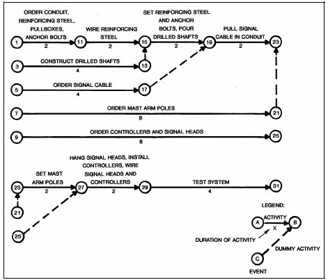
Figure 12-3. Example of CPM Network Diagram
The network diagrams should be updated periodically to account for factors which would delay project completion. These factors include longer delivery dates, delays caused by weather, change orders, etc.
Software to facilitate development and updating of CPM networks is commercially available.
Bar Charts
Figure 12-4 (13) shows the use of bar charts as a method of project scheduling. This bar chart for the Greensboro, North Carolina, Traffic Control System depicts the time relationship for completion of the various project tasks. Starting and ending dates and durations are shown for the various tasks as well as milestones (the start or completion of a task). The interdependency of tasks may be indicated by a dashed line or other symbol (e.g., M6 indicates the interdependency of acceptance tests for controller assemblies and the installation of communications lines).
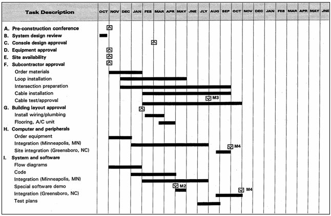
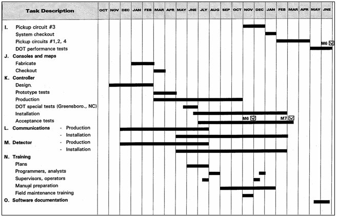
Figure 12-4. Greensboro, NC, Traffic Control Project milestone Schedule(13)
Gantt Charts
The Gantt Chart technique (14) uses an upper horizontal bar to present the planned schedule for the task. Another bar, just below this bar, charts the completed portion of the schedule. Colors usually facilitate legibility. Gantt Chart techniques prove most useful when the different tasks depicted are not related.
12.7 Implementation Pitfalls
The previous discussions of system design and implementation have focused on those positive steps that lead to successful system acceptance.
The following discussion presents the reverse perspective. Gleaned from the results of discussions and contact with system users, these pitfalls should assist in avoiding mistakes made in the past. In each case, the discussion presents the generalized pitfall, and then describes suggestions for avoidance. They are not presented in order of importance.
Inexperienced Contractors
Some contractors view the installation of traffic control systems as just another highway job. Failure to recognize the systems integration needs of such a project results in delays and additional costs to the contractor. In some cases, traffic control projects represent a small portion of a large general construction project. This virtually assures that a subcontractor will perform this critical element. Additional control of contractor and hardware selection may be required for this situation.
This pitfall can best be avoided by:
- Separating control system elements from large projects where they may be lost, and
- Where procurement regulations permit, requiring contractor pre-qualifications on the basis of demonstrated experience.
Construction Management
Construction management entails the following activities by the project engineer:
- Inspection of day-to-day construction activities,
- Witnessing of acceptance tests, and
- Other technically oriented duties.
Further, it involves record keeping, in accordance with state and Federal requirements, of items such as:
- Review and approval of shop drawings,
- Identification of need for change orders (including negotiation with the contractor on the change and compensation), and
- Obtaining necessary reviews and approvals prior to authorization.
Construction management requires both a high degree of technical knowledge and experience in managing contracts. While typical state project engineer and inspection personnel are generally proficient in project management for typical highway construction jobs, they may lack electronics and control system technical expertise. In contrast, city traffic engineers and signal maintenance personnel may have the technical expertise but little experience in project administration. Project engineers assigned from either background may tend to retreat to the familiar, with an attendant negative impact on effective project management.
Some projects have experienced problems with the inspection of system construction, ranging from token, ineffective inspection to unyielding insistence on a strict interpretation of specifications. Most common is the failure to anticipate the contractor's schedule and pace of construction and thus not match it with qualified inspectors. In some cases, inexperienced or inadequate numbers of personnel have been assigned. The best technical inspectors for any system are individuals who will operate and maintain the system once completed. If possible, they should be assigned inspection duties and have their other routine activities rescheduled to minimize conflicts.
These needs should be carefully considered in planning the project. Desirably, a team approach will be taken, with a project engineer having access to technically qualified personnel for specialized inspection tasks as necessary.
The channels of higher authority should also be identified and a working relationship established. A formal or informal project committee may be useful so that everyone involved can:
- Periodically meet,
- Be apprised of the broad picture,
- Review progress, and
- Address potential problems before they become critical.
Maintenance and Protection of Traffic (MPT) During Construction
Disruptions to traffic during construction are expected. Most agencies require a maintenance and protection of traffic plan to be incorporated into construction contracts. These plans specify lane usage during construction and times permitted for construction to avoid peak-hour interference. These plans, however often do not incorporate provisions for construction impacts downtown during a Christmas shopping rush or, of more frequent concern, signal coordination during construction, i.e., how many signals can operate uncoordinated. To avoid such pitfalls, MPT plans for maintenance of traffic during construction are necessary should address issues such as these.
Database Development
Computer-based traffic control systems require an extensive database to operate. Database development may be required at the system level, subsystem or section level and at the local level or intersection level. Computer generated color graphics files may also be required at these levels. Frequent problems have been encountered when no specific organization was assigned responsibility for necessary traffic surveys and developing, coding, input, and debugging of database information. Without clear definition, this responsibility may inadvertently fall on the user.
Databases can be developed by:
- Agency or consultant prior to PS&E completion,
- Agency or consultant after PS&E completion,
- Contractor, or
- Shared by consultant and contractor.
It is recommended that one of the above alternatives be determined early in the process. The specifications should clearly identify the contractor's responsibilities. If a consultant prepares the database, the necessary contractual arrangements should be established.
Insufficient Staff for Operations and Maintenance
Overselling the capabilities of traffic control systems as alternatives to staff can prove a mistake. Systems must be maintained and actively managed to provide effective service. Although new hardware may indeed eliminate unreliable, high-maintenance equipment that has exceeded its useful life, perhaps even more sophisticated maintenance may then be required. In addition, equipment with greatly expanded capabilities may actually require more operations staff to realize its full potential.
The timing of staff additions is also critical. For example, system operators need to be employed and available to receive training provided by the contractor.
Utility Coordination
The installation of underground conduits and / or overhead cables may cause conflicts with other public utilities. Regardless of how thoroughly the designer locates and documents existing utilities, some will be found in unexpected locations when construction begins. The Contractor must be made to understand that utility runs shown on the plans are approximate and that it is the Contractor's responsibility to confirm utility locations.
Good documentation of existing conditions can avoid serious problems in utility coordination but unforeseen situations will undoubtedly arise. The design process should visualize the most likely problems and plan a response. For example, if plans call for reusing existing conduit, it is likely that old cable cannot be removed because of conduit collapse and therefore, the conduit cannot be reused. The planned response might include a bid item for conduit replacement to adequately compensate the contractor for attempted reuse of existing conduit followed by replacement. An alternative approach would test the conduit during the design phase to avoid expensive change orders and delays.
Planned Use of Untested Facilities or Techniques
Problems have been experienced in two different ways with the planned use of untested facilities or techniques.
First, from a construction viewpoint, one agency planned to use existing telephone company underground ducts for interconnect cables. Routing and design was based on available mapping and duct-use records of the company. No funds were allocated during the design process to rod the ducts and verify open paths-a task that was placed on the contractor. During cable installation, since a number of blocked paths were found, duct replacement was not possible during the available timeframe. Therefore, alternate paths with inefficient routing and resulting contractor change orders were necessary.
Second, with respect to hardware and applications software, use of new technology may engender unexpected problems. Being the first to use a product, software, or technique that attempts to advance the state-of-the-art poses risks.
Alienation of Maintenance Staff
The acceptance of new traffic control systems by all levels of an operating staff proves very important to successful system operation. It is fostered by active involvement-not only during installation but also during both the design and pre-design activities.
Maintenance staff in particular may feel threatened by a new system, particularly if it contains a large amount of unfamiliar new hardware. They may have unexpressed concerns about the system's impact on their job security, doubts about their skills to maintain it, and feelings that the engineer's new toy just means a more difficult job for them. The following may minimize such fears:
- Early involvement of maintenance (and other) staff in system feasibility studies and system selection to assure proper consideration of reliability and maintainability issues,
- Assurance of early, thorough training tailored to staff needs, and
- Opportunities for involvement through construction inspection.
Privatization of Operations and Maintenance
A number of traffic agencies and jurisdictions have used contract maintenance in the past. Privatized operations have increased in recent years. Problems such as union contracts for the privatized or related positions or the alienation of the remaining staff may present problems. However, the cost savings or larger base of experienced personnel available in the private sector may outweigh these problems.
While maintenance is commonly privatized for both signal system and freeway ITS, privatization of operations is more common for freeway systems.
This discussion of pitfalls is by no means complete. Traffic control systems, because they must be installed in full public view and have daily impact on motorists, offer highly visible opportunities for criticism when things go wrong. Thoroughness in design and construction planning is a necessity, along with strict attention to details during construction. The hardware problems can be identified and corrected-but the people problems require constant attention.
1. "City of Pasadena Traffic Management System Phase 2, Preliminary Design Report." JHK & Associates, March 1993.
2. "Preliminary Engineering Report, City of Salem Traffic Signal Control System." Meyer, Mohaddes Associates, and JRH Transportation Engineering, November 1993.
3. "Federal Register." Vol. 67, No. 237, December 10, 2002 (www.access.gpo.gov/ su_docs/fedreg/a021210c.html).
4. Meier, H.W. "Construction Specifications Handbook." Prentice-Hall, Inc., 1975.
5. "Standard Forms of Agreement." Engineers' Joint Contract Documents Committee, National Society of Professional Engineers, Washington, DC, November 1983.
6. "Installation of Highway Traffic Signals." Item 632, Standard Specifications for Construction of Highways, Streets and Bridges. Texas State Department of Highways and Public Transportation, September 1, 1982.
7. Salwin, A.E. "The Road to Successful ITS Software Acquisition: Volume 1: Overview and Themes." Mitretek Systems, Federal Highway Administration Report No. FHWA-JPO-98-035, Washington DC, July 1998.
8. "Computer Controlled Traffic Systems Implementation Package." PRC Voorhees, Division of PRC Engineering. Federal Highway Administration Report No. FHWA-IP-82-21, Washington, DC, December 1982.
9. "Central Business District Traffic Control System (CBDTCS) System Specification." Contract Number 79-200, City of Dallas, Texas, Department of Street and Sanitation Services, 1979.
10. Simon, M.S. "Construction Contracts & Claims." McGraw-Hill Book Company, New York, 1979.
11. Hansen, G.A. "Why to Use CPM Scheduling." Public Works, October, 1994.
12. Rubin, R.A. et al. "Construction Claims, Analysis, Presentation, Defense." Van Nostrand Reinhold Company, New York, 1983.
13. "A Traffic Control and Surveillance System for Greensboro, North Carolina." Honeywell, Inc., Hopkins, Minnesota, October 1973.
14. Glueck, W.F. "Management." Dryden Press, Hinsdale, IL, 1980.