Road Weather Information System
Environmental Sensor Station
Siting Guidelines
April 2005
3.0 Site Selection
Correctly selecting an ESS site is very important to the overall effectiveness of the sensor suite and the representativeness of its observations. An ESS installed at a poorly chosen location can result in unrepresentative sensor readings, servicing difficulties, and even damage to the ESS from natural runoff and ponding in low lying areas and from road maintenance activities such as snow removal. The site selection objective is to locate the ESS where its observations will be most representative of the area or roadway segment of interest. Meeting this objective requires the DOT planning team to minimize non-weather influences such as those that may result from nearby buildings, billboards, tall vegetation, elevated portions of the highway, bridges, or topography. DOTs making ESS siting decisions should consider the seasonal characteristics of the sites. Site conditions can change significantly from summer to winter when sun angles are low and trees lose their foliage. Unfortunately, the ideal ESS site will rarely be found. The very nature of the roadway environment, narrow rights-of-way, the surrounding terrain, and even the traffic itself can impact the effectiveness of the ESS. Site selections are further complicated by the need to meet ESS power and communications requirements. Consequently, DOT planners will most often be in the position of making tradeoffs when selecting the ESS site and even when making decisions on individual sensor placement. The ESS siting guidelines can serve as an effective tool when making these difficult decisions.
3.1 Regional Site Guidelines
Regional sites are designed to provide road weather observations considered to be representative of the conditions along a given road segment. The observations from the regional ESS can support monitoring road conditions throughout the highway system and running road weather forecast models, such as those used in highway maintenance decision support systems. The regional site can also provide additional data for incorporation into more general weather forecast models such as those employed by the NWS. To ensure the regional ESSs provide data representative of the area, they should be located along uniform roadway conditions selected to minimize local weather effects and the influences from outside non-meteorological forces such as local heat and moisture sources and wind obstructions. A regional ESS should be sited on relatively flat, open terrain. To reduce the effects of traffic and road maintenance activities, regional ESS sites should be sought on the upwind side of the road based on predominant wind directions, e.g., on the north side of the road if winter conditions are the primary focus and the prevailing wind is northerly. Deviations from the siting criteria in Section 4.0 should be minimized to reduce the possibility of selecting sites impacted by local effects.
3.2 Local Site Guidelines
Local sites are those that require siting of sensors in areas that are specifically designed to satisfy a road weather information requirement along a short segment of roadway or a bridge. Examples of these requirements include: (1) road surface conditions such as historically cold spots that create slippery conditions or a location where significant blowing, drifting, or heavy snow accumulation occurs, (2) surface flooding on low lying road segments, (3) visibility distance where the local environmental conditions contribute to low visibility (e.g., a large local moisture source), or (4) high winds such as those occurring in hurricanes and terrain-induced crosswinds along a confined valley or ridge top. These local requirements may require the use of additional sensors or the siting of sensors in a location that is specifically selected to detect and/or predict a local roadway condition or weather phenomenon. At local sites, the primary consideration is detecting the road weather condition of specific interest to transportation operations and maintenance activities.
In many cases, local weather conditions or weather-induced road conditions may require a different assortment of measurements and sensors on an ESS. Some examples of these local conditions include roadway segments abnormally susceptible to ice, frost, snow, low visibility, dangerous crosswinds, and roadway flooding conditions. Other phenomena, like mudslides or rockslides, can affect roadways, but these are not covered here due to the lack of adequate sensors that can be used in the roadway environment to detect such events.
3.2.1 Slippery Pavement Conditions
These conditions usually occur in historically cold locations prone to standing water or the development of ice, frost, slush, or snow due to local weather or geographic conditions, e.g., a low spot on the road, elevated roadway or bridge, a predominantly shaded area, or locations susceptible to snowfall, blowing/drifting snow, refreeze, or frost. In these cases, the purposes of the sensors are to detect or monitor the roadway temperature and pavement conditions.
Pavement sensors that monitor roadway or bridge deck temperature, surface condition, or chemical concentration and freeze-point temperature should be installed in locations that experience icing conditions. This may result in the surface sensors being placed in more specialized locations such as multiple traffic lanes, areas subject to blowing snow, or elevated roadways. The addition of dewpoint/frost-point and/or relative humidity sensors will help monitor conditions that may lead to the development of road frost. In areas where road frost is a problem, mounting a dewpoint sensor close to the pavement height should be considered.
3.2.2 Low Visibility Conditions
These conditions usually occur in locations where local moisture, smoke, or dust sources exist or in valleys or road depressions that trap cool moist air. In these cases, the purpose of the sensors is to detect a reduction in visibility or an increase in moisture in the atmosphere, and the speed and direction of the wind. Moisture and particulate matter can be man-made, such as from a power station, waste treatment plant, mining area, plowed field, or vehicle traffic, or can occur naturally from a river or swamp, a sandy or dusty area, or blowing/drifting snow. For locations with frequent low-visibility conditions, DOTs may want to consider providing traffic safety warnings via dynamic message signs.
Visibility, temperature, humidity, and wind sensors should be installed adjacent to the roadway or in areas influenced by local sources of moisture (liquid or solid) or dust, such as on or near bridges or in confined roadway cut areas. The visibility sensors should also be installed such that they represent the atmosphere 6.5 to 10 feet (2 to 3 meters) above the roadway. Siting visibility sensors closer to the roadway may degrade their performance due to the influence of salt spray from snow and ice control practices, or passing vehicles, and they may require more frequent maintenance. A thorough analysis of the particular location characteristics (e.g., source locations, obstructions, etc.) will help find an acceptable siting location.
3.2.3 High Wind Conditions
High winds and strong gusts frequently occur on bridges, confined valleys where channeling occurs, open fields unprotected by trees or structures, or on ridge tops. In these cases, the purpose of the sensors is to monitor and detect the onset and duration of high winds and wind gusts at the height most likely to affect the stability and handling of moving vehicles.
For these conditions, additional wind sensors can be placed where they represent the winds likely to affect motor vehicles. This can be on bridges, open areas with long wind fetches, and rapid wind shear areas (e.g., exit from within road cuts, tree stands, and large structures). For dangerous crosswind conditions, wind measurements normally taken at 33 feet (10 meters) can be supplemented by an additional wind sensor installed at a height of 10-16.5 feet (3-5 meters) so it will measure winds most likely to affect high-profile vehicles. Care should be taken to avoid siting the wind sensors too close to moving traffic or in wind shadows (i.e., the downwind side of bridges, signs, foliage, or buildings). In cases where wind channeling is caused by valleys or canyons, consideration should be given to installing sensors at the entry and/or exit areas of these features where wind shear can be experienced.
3.2.4 Water Level Conditions
Flooding can occur on bridges, in underpasses, or in other low lying road segments adjacent to permanent or intermittent water bodies. Such conditions may occur during or after heavy precipitation, thawing, tidal, river ice jam, persistent counter-flow winds, or storm surge events. During these events, the sensors monitor water level conditions and detect flooding. These data can support emergency response activities and can result in the closing of roads to prevent loss of property or life.
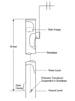
Sensors including pressure transducers, ultrasonic sensors, and float gauges installed in standpipes can be used to measure the water levels and monitor flooding conditions. The standpipe, as illustrated in Figure 5, is normally a 10-12 foot (3-3.7 meter) rugged pipe with a diameter of 12 inches (30.5 centimeters). The sensors and associated electronics are packaged within the pipe. Some vendors offer these sensors with a rain gauge mounted near the top of the pipe. The float gauge can be installed in normally dry areas where runoff and precipitation accumulate. The pressure transducer can be used to monitor water levels in standing bodies of water such as lakes and reservoirs. The ultrasonic sensor monitors water levels in fast moving streams and rivers. If installed on the side of a bridge to measure potential flooding, the sensors should be sited on the downstream side in a location with low water turbulence. Water level sensors can also be installed adjacent to the low point of the roadway or next to any road segment subject to flooding.
While not yet widely used as part of an ESS sensor suite, solid state water sensors that detect the presence of conductive solutions can warn of rising water levels. The sensor’s electrodes are positioned at a desired water level detection height. When water reaches the electrodes, a warning signal can be sent to an ESS RPU.
|
Figure 5. Typical Standpipe Configuration |
3.2.5 River Bed Scouring Conditions
Scouring of river beds adjacent to a roadway bridge pier or abutment foundation can result in the undermining of the foundations and their eventual failure. Scouring can occur at any time but usually occurs during flooding conditions. The State bridge engineer can be consulted to determine if there are scour susceptible stream beds on the road segment under consideration for an ESS installation. Sensors used to measure scouring can provide warnings of danger to the integrity of the bridge foundation. A liquid-filled load cell buried in the river sediment weighs the sediment, water, and air above it, and an accompanying pressure sensor provides the weight of the water and air. The difference in the weights indicates the weight of the sediment and can be monitored for scouring. Additional optical, conductive, radiometric, and acoustic scouring sensors are under development. Scouring sensors are buried in the sediment adjacent to a bridge pier or foundation. Scouring sensors are not normally included as part of an ESS but are presented here for DOT consideration.
3.3 Siting Tools
Local road maintenance personnel can provide valuable insight into weather-related safety and mobility concerns along the roadway they maintain. In addition to tapping their experience, the site selection team can employ several tools to help identify locations suitable for an ESS installation.
3.3.1 Thermal Mapping
Thermal mapping can be a useful tool in planning the installation of an RWIS ESS network and in selecting ESS sites. Road thermal analysis, or thermal mapping, is the use of vehicle-mounted, downward-pointed infrared radiometers to survey a selected road segment to map the position of warm and cold spots along the roadway. This analysis can (1) better define the thermal characteristics of road segments (e.g., cold spots) and aid in the selection of locations to site roadway sensors for monitoring and forecasting surface icing conditions and (2) help identify locations that are representative of other locations, thereby possibly reducing the number of ESS installations required. The thermal mapping data are usually collected in the early morning, before sunrise, when surface temperatures are the coldest. Data are usually collected under clear sky, cloudy sky, and wet pavement conditions, as roadway temperature patterns differ under each condition.
An analysis of the data (similar to the work accomplished by the Nevada DOT9 and research conducted by Lee Chapman, John Thornes, and Andrew Bradley10 and Jorgen Borgen et al11) determines where along the stretch of roadway the pavement temperature will be the minimum under the different weather and road conditions. This analysis can be one method for determining points of interest for frost and icy pavement formation and for ESS site determination and roadway characterization. Thermal mapping can help optimize the number of ESSs to be installed. Fewer ESS installations may be needed if the roadway thermal profiles and properties are better known. In cases where it reduces the number of ESS installations, thermal mapping can pay for itself.
3.3.2 Portable Environmental Sensor Systems
While offering limited utility, portable sensor systems can be used to survey potential permanent ESS sites. These portable systems can include a uniform suite of sensors or may only contain a couple of sensors if the road weather requirement is very specific. Normally, portable ESSs do not include road sensors that must be implanted in or below pavements. Portable systems can be used to detect locations of concern or to monitor construction sites and projects. Mobile observing platforms (e.g., vehicles, trailers) can be used in much the same way to assist in locating specific points of interest for future ESSs.
9 Vaisala, Inc. State of Nevada DOT Thermal Mapping Final Report 2000, 2000.
10 Chapman, Lee, et al. Statistical Modelling of Road Surface Temperature from a Geographical Parameter Database. University of Birmingham, Climate & Atmospheric Research Group website.
11 Borgen, Jorgen, et al. The Impact of Screening on Road Surface Temperature. Meteorological Applications, Vol. 7 pp. 97-104. 2000.
|