Comprehensive Truck Size and Weight Limits Study: Pavement Comparative Analysis Technical Report
Appendix B: Project Plan/Schedule
1.1 General Approach for Pavement Comparative Analysis:
This section provides an overview of the approach that will be followed in completing the pavement comparative analysis. A total of 40 representative pavement sections, 10 sections within each of the 4 primary climatic zones in the United States, will be selected for analysis in this area of the Project. The AASHTOWarePavement ME Design® model will be used in this analysis and will be run for each of these 40 sections to determine a base case for the expected pavement life cycle under representative average traffic conditions (e.g., representative of the mix of vehicle types and operating weights that might be expected based on compilation and analysis of large quantities of Weigh-in-Motion (WIM) data. An initial analysis of climate variability within each climate zone will be performed to ensure that the sites selected represent typical weather effects for that zone. To the extent possible, Long Term Pavement Performance (LTPP) program sections will be used as a basis for each sample section and will adjust base case parameters as required to make sure that each sample section represents the pavement performance history that would typically be expected.
While compiling the data required for each of the 40 selected sections, the first step will be to perform a complete analysis of a single pavement section to illustrate, evaluate, and, if necessary, adjust the analysis method that will be used for all the sections. For this pilot section, traffic inputs will be varied in ways that represent traffic shifts likely to occur as a result of the various truck scenarios, and will estimate the effects of a small sample of illustrative vehicle class and operating weight groups on the life of the pavement. This will require a series of runs of the Pavement ME Design® model during which all factors except traffic are held constant.
The multiple runs for each sample section will enable an evaluation of changes in pavement service life as a result of changes in truck travel associated with each modal shift scenario. These changes in pavement service life will be translated into pavement cost changes associated with size and weight scenarios.
1.2 Detailed Project Plan – Comparative Analysis of Truck Weight Impacts on Pavements
As outlined above, this analysis will consist of seven steps:
- Select representative locations in each climate zone,
- Select sample pavement sections,
- Apply Pavement ME Design® to pilot sample section,
- Apply Pavement ME Design® to base case traffic conditions,
- Apply Pavement ME Design® to changes in travel by selected illustrative vehicles,
- Apply Pavement ME Design® to scenario traffic variations, and
- Expand sample results nationally.
The sections below describe each of these steps.
1.2.1 Select Representative Locations in Each Climate Zone
In this subtask, an analysis of sample sections of each pavement type in each of the four broad climate types—wet freeze, dry freeze, wet no-freeze, dry no-freeze—will be completed. These represent the traditional pavement climatic zones as well as the broad categories covered in the LTPP. Pavement ME Design® uses very detailed climatic data that varies considerably within each broad climatic region, so this exercise will help to assure that the weather station data shows reasonable values and candidate sections can be pared down to one location per climatic zone that represents the entire region. The study team will note the five parameters predicted in the Climate Summary, along with elevation, for each of the locations per climatic zone. The team will perform base runs at five different locations within each zone and will select sites representative of the five locations that to provide results that best represent the overall climate zone. Locations that make use of at least two, and ideally three or more, weather stations will be chosen to minimize issues of missing and spurious data that are sometimes observed for individual weather stations.
In this preliminary analysis, the traffic will be held constant using the default data in the Pavement ME Design® model and will be limited to one representative flexible pavement section and one representative rigid pavement section. Cross-sectional thicknesses that are designed to develop noticeable levels of distress will be used for the purposes of this preliminary analysis. Noticeable levels of distress are defined as the level that would trigger some type of rehabilitation action. The level of distresses initially selected will be the threshold values included in the MEPDG Manual of Practice. Other climate constants will be based on the LTPP SPS-8 original experimental plan (SHRP 1992a) sections and LTPP GPS sites, as per the four climatic zones. The results of this first analysis will be used to select the actual sections (to be used in the full factorial analysis) that most closely follow the median of the characteristics for this broad climate zone. The median will be based on the freezing index (primary factor) and number of freeze/thaw cycles (secondary factor) for the dry-freeze and wet-freeze sections and the mean annual precipitation (primary factor) for the dry-no freeze and wet-no freeze sections.
1.2.2 Select Sample Pavement Sections
Four pavement types will be considered for selection—flexible: new asphalt concrete (AC) and AC overlay on AC; rigid: jointed plain concrete pavement (JPCP); and, composite: AC over JPCP. Together, these pavement types represent the overwhelming majority of pavements used on streets and highways in the U.S. The basic premise is that the analysis should isolate the impacts of traffic shifts and load configurations, while holding other parameters constant. In order to achieve this goal, the baseline pavement sections will be based on the following criteria: 1) use actual traffic characteristics on our highways currently, 2) use sections with modern-day designs and materials (as close to actual site sections as possible), and 3) use the subgrade properties on site (preferred). The pavement layer thicknesses and material types will represent the median values included in the LTPP database. There have been multiple studies that have prepared histograms of the different pavement structures and layer thicknesses. These results will be used to establish the initial structures.
For rehabilitation, AC over AC or AC over JPCP, the condition of the existing pavement prior to overlay placement can have a significant impact on the predicted distresses. Thus, the condition at rehabilitation will be the threshold condition established above as the design criteria. These are provided in the AASHTO MEPDG Manual of Practice. This assumption will ensure that the new design and rehabilitation design will represent consistent values triggering some type of rehabilitation.
Within each climatic zone, truck traffic levels can vary by several orders of magnitude, with corresponding effects on pavement design and performance. Different truck travel values will be selected that correspond to three different truck traffic levels for flexible pavements and two different truck traffic levels for rigid pavements. For example, in identifying the two different traffic levels for rigid pavements those levels will be defined as above-average rural interstate highway traffic levels and below-average rural principal arterial traffic levels, respectively, in each climatic zone, making use of truck travel levels reported on the most recent available HPMS sample data file. Existing sections of interstate or other State primary routes that are instrumented for monitoring traffic, temperature profiles through the layer, and pavement responses will be considered within the climatic zones first (e.g., through the HPMS). Examples of these include active LTPP sections as well as State-led sections like the Weigh-in-Motion Pavement Investigation (WIMPI) in Maine (flexible pavement), various Superpave Instrumented Stress-Strain Investigation (SISSI) flexible pavement sites in Pennsylvania, and the MnRoad sections near Minneapolis, as well as the LTPP GPS and SPS-8 sections. LTPP has defined about 23 sites that are considered their “gold” standard in terms of accurate normalized axle load distributions for the standard truck classes. These WIM sites were identified and established within the FHWA/LTPP pool fund study. These sites will be reviewed as potential sites for extracting and using the axle weight data as the baseline condition for different roadway classifications. The normalized axle load distribution from each site has already been established under an LTPP-sponsored project.
Because the base modulus may have a significant effect on the relative magnitudes of damage caused by heavy trucks in rigid pavements, an analysis of two different base types for the JPCP will be used: granular and asphalt-stabilized. Consideration of asphalt and aggregate base type for flexible pavement is directly considered by varying the thickness of the asphalt surface layer for varying truck volumes. A conventional asphalt concrete pavement structure, as defined by the MEPDG Manual of Practice will be used. This family of flexible pavements includes an unbound aggregate layer beneath the asphalt surface layer. The thickness of the crushed aggregate base layer will be determined from the median values included in the LTPP database for this family of pavements.
The subgrade material property inputs can be generated for any location in the US using any of four different sources: 1) the actual subgrade properties on site (preferred); 2) the Level 3 soil properties from the AASHTO MEPDG Manual of Practice; 3) the LTPP GPS or SPS database (this database was used to establish the level 3 resilient modulus inputs), or 4) the NCHRP Project 9-23B Arizona State University (ASU) Soil Unit Map Application®. The ASU software tool displays an online GIS-enabled national soil database and features a query tool to identify the soil characteristics for inputs that are required by the Pavement ME Design® software. Any differences between the soil properties available in the Soil Unit Map Application and their LTPP database counterparts will be noted, where applicable.
The full factorial is shown in Figure 1 for all pavement types, climate zones and traffic levels.
- New flexible pavement total = 4 climate * 3 traffic = 12 cells.
- Asphalt overlay of flexible pavement total = 4 climate * 3 traffic = 12 cells.
- New rigid pavement total = 4 climate * 2 traffic = 8 cells.
- Asphalt overlay of rigid pavement total = 4 climate * 2 traffic = 8 cells.
This represents a total of 40 cells for a full factorial. These cells are representative of a large proportion of the US highway network (or National Highway System). Sections will be selected sections with typical representative design and materials characteristics.
1.2.3 Apply AASHTOWare Pavement ME Design® Model to Pilot Sample Section
In this phase of the project, a preliminary sample section will be identified as described in the next section and simulate traffic variations that might be expected to result from each scenario. Model runs will be used to estimate the changes in pavement life associated with changes in travel by selected illustrative vehicles. Likely illustrative vehicles will include, for example, (1) an 80,000-pound five-axle tractor-semitrailer combination vehicle with a tandem drive axle and a tandem trailer axle, (2) a 97,000-pound six-axle tractor-semitrailer combination vehicle with a tandem drive axle and a tridem trailer axle, and (3) an 88,000-pound five-axle tractor-semitrailer-full-trailer combination vehicle with single drive and trailer axles. By the time this stage is reached in the analysis, other scenario vehicles will be specified and included in the analysis as illustrative vehicles, also.
Since Pavement ME Design® includes only the 10 HPMS truck classes in its traffic inputs, the study team will subdivide several of those classes to allow a range of scenario vehicles as well as the additional detail needed for traffic shift analyses. Travel shifts will be computed and added to the detailed traffic composition by the vehicle classes, then recombined to the 10 classes needed for model input.
Applying Pavement ME Design® to the pilot section will allow evaluation and refinement of the specific model application procedures the study team will use for the rest of the sample pavement sections, as described below.
1.2.4 Apply AASHTOWare Pavement ME Design® Model to Base Case Sections
In this phase of the project, each actual selected section will be replicated as closely as possible using the input variables available in Pavement ME Design®, adjusting as necessary to match the observed distresses. If it is not possible to reasonably match observed distresses for a particular section, selection of an alternative section may be required.
As a first step in applying Pavement ME Design®, detailed traffic levels need to be set for each sample section. The rough traffic parameters known from HPMS section data (total ADT, combination truck ADT, and single-unit truck ADT) will be used for the particular selected section, as well as an appropriate set of axle weight and vehicle class distribution factors derived from a combination of current WIM data and updated FHWA VMT estimates. WIM data provided by the States to FHWA will be used, as well as the full set of WIM data collected under LTPP.
While compiling the WIM data in each State and for each highway type, the distances between combination vehicle load axles will be compiled so that modification of the Pavement ME Design® default values will be performed to better match truck characteristics for each sample section.
The full pavement analysis plan is going to answer the question of “when does the traffic shift being analyzed cause the pavement damage for a particular distress to exceed its targeted threshold value?” Exceeding the distress threshold presumably triggers the need for pavement repairs.
The analysis criteria (thresholds for each distress type), reliability level, and design period will be selected by following recommendations published in the AASHTO MEPDG Manual of Practice for each pavement type and roadway functional classification. The baseline pavement section will be held at no traffic growth (0 percent rate). Based on the findings of the preliminary climate analysis, the same multi-weather-station location will be used within each climate zone. Figure 1 shows a schematic that represents the distribution of sample sections. Within each of the cells shown, all factors will be held constant except traffic to evaluate the effect of each size and weight scenario, as described in the next section.
| Climate* | ||||
|---|---|---|---|---|
| Pavement type | Wet-freeze | Wet- No freeze |
Dry-freeze | Dry- No freeze |
| New Flexible | High Truck ADT Med Truck ADT Low Truck ADT |
High Truck ADT Med Truck ADT Low Truck ADT |
High Truck ADT Med Truck ADT Low Truck ADT |
High Truck ADT Med Truck ADT Low Truck ADT |
| AC Overlay over Flex. | High Truck ADT Med Truck ADT Low Truck ADT |
High Truck ADT Med Truck ADT Low Truck ADT |
High Truck ADT Med Truck ADT Low Truck ADT |
High Truck ADT Med Truck ADT Low Truck ADT |
| New Rigid | High Truck ADT Low Truck ADT |
High Truck ADT Low Truck ADT |
High Truck ADT Low Truck ADT |
High Truck ADT Low Truck ADT |
| AC Overlay over Rigid | High Truck ADT Low Truck ADT |
High Truck ADT Low Truck ADT |
High Truck ADT Low Truck ADT |
High Truck ADT Low Truck ADT |
* From one representative location for each, based on preliminary analysis return to Table 1
1.2.5 Apply Pavement ME Design® to Changes in Travel by Selected Illustrative Vehicles
Appropriate illustrative vehicles, the "alternative configurations" to be assessed in the study, will be identified, including two or three "base case" vehicles in common current use, as described in Section 1.2.3, and five to eight "scenario" vehicles.
For each illustrative vehicle, base case traffic mix will be added with sufficient travel by the vehicle of interest to result in an identifiable increment of loss of pavement life. For example, a loss of life of 3 months may be selected. The model will be run with a few selected increments of added travel by the vehicle of interest, and the level of travel will be adjusted until the target loss of life for each section is identified. This will enable a comparison of the relative effects of base and target vehicles, but will enable the estimation of the life cycle costs associated with each illustrative vehicle. The FHWA spreadsheet entitled RealCost will be used to calculate the life cycle cost for each scenario and example or truck traffic modal shift.
1.2.6 Apply Pavement ME Design® to Scenario Traffic Variations
Each study size and weight scenario will estimate the degree of travel shift among modes, vehicle configurations, and operating weights. The analysis of these anticipated shifts is crucial and is perhaps the most complex component of this pavement analysis, since the direction and magnitude of traffic shifts for each highway type in a State is a function of current regulations on and off the Interstate system, as well as details of each scenario. The study team will closely coordinate this effort with the work being performed under Volume II: Modal Shift Comparative Analysis, the first document in this volume of the 2014 CTSW Study, to make sure the estimates generated through the modal shift analytical work—which are likely to include differential traffic impacts for groups of States with similar current size and weight regulations—are readily translated into detailed traffic inputs needed for Pavement ME Design® model runs.
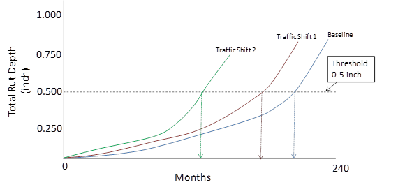
The effects of traffic shift per pavement type will be defined by the time to reach critical performance criteria. Note that these performance criteria are those typically used in design and pavement management by State highway agencies. In the context of this analysis, failure will be defined as number of months at which the key target pavement distresses are exceeded. In the case of new flexible pavements, the key distresses considered are bottom-up fatigue cracking, total rutting, and pavement ride quality (IRI). In the case of new rigid pavements, the key distresses considered are percent of slabs transverse cracked, amount of joint faulting, and pavement ride quality (IRI). The threshold values selected will be those included in the MEPDG Manual of Practice because they represent typical values used by agencies across the United States. In the case of flexible overlays, total cracking (bottom-up fatigue plus reflective cracking) will also be analyzed for its time to failure. Conducting the impact analysis in this manner allows for the calculation of the difference in pavement life (prior to pavement repair), as based solely on the traffic variables. The schematic in Figure 2 illustrates a sample of the traffic shifting matrix for a new flexible pavement and Figure 3 presents a sample of the new flexible pavement analysis of the impacts of traffic shifts on rutting.
It should be noted that the local calibration coefficients documented as examples under NCHRP Project 1-40B and included in the appendices of the MEPDG Local Calibration Guide will be used for predicting distress. Some agencies have also completed local calibration studies for both flexible and rigid pavements; however, these results will not be used within this study. The reason for considering the use of the results from NCHRP Project 1-40B is that the examples included some of the SPS experiments and test sections included in the LTPP program. This will then be consistent with the input level 3 and other parameters recommended in the MEPDG Manual of Practice.
Figure 3: Sample Traffic Shifting Impacts on Total Rutting in a New Flexible Pavement (fictional data for Demonstration Purposes only).
Changes in pavement life will be translated into life cycle cost estimates using FHWA’s RealCost software. The study team will focus on highway agency costs, meaning that the detailed temporal variation of traffic, capacity analysis, or value-of-time parameters needed for complete analysis of user costs will not be included. Instead, user costs, when they are present, will be noted whenever pavement rehabilitation is needed, as will changes in intervals of rehabilitation that will result in changes in user costs. Simplifying assumptions used in determining the user costs between different scenarios will be documented.
1.2.7 Expand Sample Results Nationally
Scenario traffic conditions will be selected for the pavement section of each type that most closely matches the characteristics of a given State and functional class, weighting the pavement types based on number of lane miles. In some cases, more than one environmental zone for a State will be applied, and the prevalence of each zone for that State will be assigned a weight, again based on lane miles. Similarly, interpolation may need to be performed on the differences between the two traffic levels in cases where highway classes have traffic that is not close to one of the sample traffic levels.
Estimates for every highway system, not just the Interstate System and the National Highway System, will be developed since these other road systems will also see traffic shifts, and traffic shifts in rural and urban areas will need to be considered separately.
1.3 Data Requirements for Pavement Comparative Analysis
The proposed approach to meet the requirements of the pavement analysis task requires a variety of data inputs, some of which are precisely the same data required by other tasks, and some of which are either unique to this task or requiring more detail than the other tasks.
1.3.1 Pavement Design and Materials Data
AASHTOWare Pavement ME Design® requires a large number of pavement design details, soil data, and other materials data. The software package includes the climate data needed for proper program operation, and includes a large quantity of nationally derived default data for nearly everything else. To properly analyze the sample pavement sections, however, pavement materials and design parameters need to be carefully matched to typical in-use pavement sections in each climate zone and at each traffic level. Steps will be taken to ensure proper and reasonable inputs are utilized and the LTPP database will serve as a reference data set.
1.3.2 Vehicle Classification Data
Vehicle classification data will be used, as appropriate, for initial estimates of truck travel for broad classes of trucks in each State on functional class. If appropriate, HPMS area wide travel counts reported by the States for the 13 HPMS vehicle classes on each highway system will be used. If these reports are not considered to be sufficiently reliable, the State-reported data will be ignored, adjusted, or aggregated as required. This has been done in previous cost allocation and size and weight studies. As noted previously, it is recommended that the LTPP “gold” WIM sites be used where appropriate to establish not only vehicle classification data, but more importantly the normalized axle load spectra for each truck class. These WIM sites were identified from the pool fund study. Using these sites adequately ties the normalized vehicle classification distribution to the normalized axle load distribution in terms of establishing a baseline condition or trend.
1.3.3 Weigh in Motion (WIM) Data
All available WIM data compiled by FHWA will be used for multiple purposes in this 2014 CTSW study, as well as the most recent years of WIM data collected for LTPP, as noted above. In previous compilations of national travel estimates and truck travel characteristics, a database has been constructed using the most recent consecutive 12 months of WIM data for each State. A battery of computer programs has been assembled to compile and analyze this data, which has been used in previous such compilations. The computer programs will be revised and updated as necessary and will provide compiled WIM data in whatever formats are required by other tasks in this study.
Detailed Vehicle Class Travel Estimates. Since raw WIM data reported to FHWA includes axle weights and distances between axles for each observed vehicle, the vehicle classifications provided by the standard axle-spacing algorithms used by the States can be estimated. This data can then be subdivided into the 13 HPMS vehicle classes and subdivided again into the more detailed classes required by the CTSW study. In general, the WIM data will be used to allocate control totals for broader vehicle class travel estimates provided by FHWA’s traffic monitoring system. If estimates of travel by the full 13 classes are used, the WIM data will be used to adjust State estimates for some or all of the truck classes based on previous observations of systematic misclassification of some vehicles. Class 13, for example, often includes two closely following vehicles whose axle spacings look like a double-trailer combination, but whose axle weights reveal that this is not the case.
In previous FHWA studies, individual WIM observations have been evaluated for validity based on the reported axle weights and spacings, and either reclassified or rejected according to explicit editing criteria. The editing criteria will be updated, refined, and adjusted to fit the needs of this study, as appropriate.
Operating Gross Weight (OGW) Distributions for Each Vehicle Class. Following the refinement of the WIM record editing criteria, operating weight distributions will be complied for each detailed truck class in each State and on each available highway class. Ideally, each State would report enough WIM data to FHWA to allow independent operating weight distributions for each vehicle class on each type of highway. In most cases, however, States collect WIM data on Interstate and arterial highways, especially rural arterial highways. Also, many States have found it difficult to collect and process traffic data accurately using the 13 vehicle class categories and so have adopted simplified schemes for classifying truck traffic. Also, some configurations can only be identified through inspection of special permit files, and some configurations cannot be identified at all. Therefore, highway types and sometimes States will be grouped to develop valid OGW distributions for many vehicle classes. In developing the estimates of OGW distributions, care will be taken to distinguish among States with varying weight regulation on Interstate and non-Interstate highways.
Axle Weight and Type Distributions. Axle weights and types have large effects on pavement deterioration and service life. WIM data provides an excellent source of information about the actual distribution of axle weights for the weight groups in each vehicle class, so that the use of unrealistic “idealized” axle weights to typify a weight class can be avoided. For example, an 80,000-pound 3-S2 is often characterized as having a 12,000-pound steering axle and two 34,000-pound tandem load axles. If the actual distribution of axle weights is 10,000 / 37,000 / 33,000 pounds, however, the vehicle will cause significantly more pavement damage than would be estimated by the standard weight distribution.
For consistency with Pavement ME Design® traffic input requirements, axle weight frequencies will be tabulated in 1,000-pound weight groups for steering axles and single load axles, 2,000-pound increments for tandem axles, and 3,000-pound increments for tridem axles. Separate frequency distributions will be developed for each weight group and each vehicle class.
1.3.4 HPMS Section Data
The latest year of HPMS section data that is available will be used and along with all available traffic estimates, single-unit truck traffic estimates, combination truck traffic estimates, and pavement condition, design, and age data that are available on this data set. This data will be used in the selection of the pavement sections, to provide a check on large-category truck travel estimates, and to expand the results of the sample pavement sections to the national highway system.
1.4 Contingency Plan for Scenario Analysis
After performing a set of varied-traffic Pavement ME Design® runs for a single pavement section as described in Section 1.2.3, an analysis of the workability of the scenario traffic variation and illustrative vehicle schemes will be conducted. If it is determined that the scheme is unworkable, modifications to the work plan will be made. Rationales for finding the vehicle schemes unworkable will be documented.
1.5 Proposed Schedule for Completion
The work described in this Plan will be completed according to the following schedule:
Desk Scan
- Draft — August 28, 2013
- Final — November 8, 2013
Comparative Analysis of Truck Weight Impacts on Pavements
- Complete pilot section analysis — December 4, 2013
- Complete base runs for all sections — January 10, 2014
- Complete scenario runs — March 21, 2014
- Draft pavement impact report — March 28, 2014
- Final pavement impact report — April 22, 2014
- Final Technical Report — May 4, 2014