2.0 Technical Approach (Page 2 of 2)
2.6.3 AVI Infrared (IR)
AVI IR systems utilize an in-vehicle tag that is read by a reader/transmitter installed in the toll lane. IR technologies include IR tags and smart cards with IR tags. An IR tag – similar to an RF tag – is a device located in or on the vehicle that is used in conjunction with an in-lane IR antenna to communicate identifying information about the vehicle and customer to the toll system. The information stored in the tag is fixed (read only) and cannot be changed. The IR tag does not have any processing capability.
A smart card with IR tag essentially operates in the same functional manner as a smart card with RF tag – the key difference is its method of communication (an IR vs. an RF frequency). AVI Infrared technologies have much the same basic advantages and disadvantages as AVI RF technologies.
Border Applications of Automatic Vehicle Identification Technology
AVI RF and Infrared advantages include proven technology and moderate cost. Disadvantages include infrastructure costs, some susceptibility to environmental influences, and the need for cross-border operational agreements.
2.6.4 Enhanced Common Inductive Loop
Loop detectors, are the primary source of quantitative traffic data in the U.S. They are usually hexagon-shaped wires buried in the road. When a vehicle passes over a loop detector, its metallic mass causes fluctuations in the detector's inductance. Until recently, the cards used with loop inductors only read in a pulse or a presence mode, which produced a digital output. Using this technology, when the measured inductance crossed a threshold set in the detector card, its field controller read it as a digital "one," or occupancy. When the vehicle moved off of the detector, the field controller then read a digital "zero," or unoccupied. This technology did not differentiate for the size of vehicle.
The principal components of an inductive loop detector are one or more turns of insulated wire buried in a shallow cutout in the roadway, a lead-in cable that runs from a roadside pull box to the controller, and an electronics unit located in the controller cabinet. The insulated wire loop can be excited with a signal ranging in frequency from 10 KHz to 200 KHz and functions as an inductive element in conjunction with the electronics unit. The disadvantages of the basic inductive loop technology include:
- time and difficulty of installation (involving up to a dozen saw cuts),
- fitting the loop to the cuts without crimping or nicks,
- changes to inductance caused by the environment,
- vehicle's offset in a lane, which adversely affects repeatability,
- vehicles with large differences in inductance, and
- vehicles changing lanes.
Data supplied by these loop detectors are vehicle presence, count, and occupancy. When used in pairs to form a "speed trap," they can also measure speed directly. Two loops placed close together in this way gauge vehicle speed based on the time between occupancy of the two sensors. Speed and occupancy can be used to determine a vehicle's length. When a vehicle stops on or passes over the loop, its inductance is decreased indicating the presence or passage of a vehicle. The electronics unit responds to the change in inductance and conveys the vehicle presence data to the controller when requested. This basic inductive loop technology was developed in the 1970's and '80's and did not change much until recently.
However, there are now loop detectors that have the capability to produce a vehicle inductive signature through a serial port on the detector card. This unique signature results from the net decrease in the detector's inductance when the metallic mass of a vehicle passes over the magnetic field generated by the inductive loop. Inductive signature analysis can allow vehicle classification data to be derived. In other words, instead of knowing that some vehicle of indeterminate size passed over the detector, the characteristics of the signature can be used to determine whether, for example, the vehicle was a passenger car or a large truck.
The California Partners for Advanced Transit and Highways (PATH) has conducted much research into this new technology. PATH took a three-phased approach to improving this technology. First, they used existing loop detector hardware but upgraded the communication protocols and analysis software. The second phase replaced existing loop detector cards with commercial detector cards capable of outputting a vehicle's inductive signature. This approach not only permits most vehicles to be matched, it also gives more accuracy to local counts and vehicle classifications. It can offset many detector failures by automatically adapting to changes in loop inductance. Finally, that ability helps to improve a number of current reliability problems that exist with inductive loop technology. PATH's third phase intends to use more advanced detector hardware and simpler, cheaper, more reliable loop geometries.
There are two different systems that have been developed for classifying vehicle signatures. One system uses a Self-Organizing Feature Map, which is an artificial neural network. On a test, this technology was said to have been able to classify 300 test vehicles with an accuracy of 85 percent (the classes involved were SUV, limousine, bus truck, car towing trailer, and semi-trailer truck). A second system uses, for classification, a heuristic discriminant algorithm. This approach was said to yield 81%-91% overall classification rates in testing.
With these accuracies, inductive signatures can be applied to some new transportation measures. Data can be derived that were not previously accessible, including section travel time. Speeds that previously derived from double inductive loop configurations can now be derived with single loops by using vehicle inductive signatures. Thus, there are new ways to collect important real-time data through the use of inductive signatures. There are a number of new applications that emerge from this improved technology that are beyond the purpose of this report.
Border Applications of Automatic Vehicle identification Technology
Among their advantages, loop detectors are a common, recognizable sensor. They have relatively inexpensive purchase and installation costs. One of their disadvantages is that where crossing vehicles are mostly similar (i.e., large trucks), differentiation will be more difficult than if there are more diverse vehicle types in the traffic flow. How accurately this enhanced loop-detection system can positively identify a specific truck among a throng of other trucks remains to be seen, so therefore it is a potential drawback.
2.6.5 Signature Inductive Sensors (Enhanced Loop-Based Traffic Surveillance)
One company interviewed in conjunction with this report had an inductive signature product under development. Their product feature claims include:
- single roadway cut installation, which can cover multiple lanes and covers lane edge to lane edge;
- faster, safer, and easier installation (approximately ½ hour vs. 4 hours);
- shorter traffic stoppage/impedance times, with minimal travel time loss;
- more defined signature data;
- uniform data over entire lane of traffic, regardless of vehicle lateral offset within the lane; and
- does not miss turning or off-center vehicles like other loop technologies.
Border Applications of Automatic Vehicle Identification Technology
The same advantages and disadvantages that applied to the previous category – enhanced common inductive loop – apply to signature inductive sensors as well. However, this technology is intended to produce better discrimination among vehicles.
2.6.6 Mobile Phone Locating
A recent study has found that 49.5 percent of cellular phone calls were placed while driving. While the percentage of wireless calls placed by drivers – compared to those placed in home or office – has declined somewhat, the number of such calls has grown considerably. There are now said to be nearly 120 million wireless subscribers in the U.S. The popularity of cell phone use has given rise to surveillance technology that uses geolocation of those callers.
The CAPITAL (Cellular Applied to ITS Tracking and Location) Operational Test and Demonstration Program, which was conducted in 1994 in the Washington, D.C. metropolitan region, was one of the first actual field deployments of technology to geolocate cell phone calls. This ITS operational test made extensive use of the existing cellular infrastructure for both area wide surveillance and communications. Equipment was co-located on Bell Atlantic mobile towers to detect cellular users and geolocate phones on designated roadways. The project explored questions related to positioning accuracy, incident detection accuracy, possible applications in a traffic management center (TMC), and potential for replacing or supplementing certain other technologies, such as loop detectors and video surveillance. The CAPITAL operational test represented a first-generation approach to geolocation. It utilized RF direction finding and required substantial infrastructure, and it required both line of sight and multiple cell towers to function.
In the years since the CAPITAL project demonstrated some of the attractive features of geolocation, the technology has advanced. "New modes of cellular geolocation are available. The installed base of cellular telephones is far greater, and includes a wider variety of cellular protocols, both digital and analog. This affords the opportunity to focus more directly on transportation management issues, such as the accuracy of speed estimates derived from dynamic geolocation measurements, applications to incident detection and management, and cost-benefit analysis."
Consequently, another mobile call tracking prototype system is currently being tested in the Washington, D.C. metropolitan region. This ITS operational test is the Capital Wireless Integrated Network (CapWIN). Following along the same lines as the CAPITAL project, it implements a wireless communications network that serves the core mobile communication functional needs of transportation, law enforcement, fire and EMS in the Washington metropolitan region. Its network supports multiple in-vehicle platforms.
Something that has advanced location services is Emergency 911 (or E-911) calls for emergency assistance. As part of the Federal Communications Commission's E-911 mandate, all cellular service providers must be able to accurately estimate the location of incoming wireless Emergency 911 calls by October 2001. Part of that requirement is that wireless service providers have the ability to pinpoint and report to Public Safety Answering Points (PSAPs) the locations of all 911 callers within an accuracy of 100 meters in 67% of all cases.
In response to this need, a company participating in the CapWIN operational test has developed a technology that allows cellular phone calls to be tracked and monitored anonymously. The proprietary Location Pattern Matching process used by this system determines a wireless subscriber's location by measuring the distinct RF patterns and multi-path characteristics of radio signals arriving at a cell site from a caller. The technology identifies the unique radio frequency pattern or "signature" of the call and matches it with a similar pattern stored in a central database. This system does not require direct line of sight to multiple base stations to identify locations. Since this system can use its own antenna arrays to detect RF signals, no alteration to existing cellular base stations or subscribers' handsets is required.
In operation, "a mobile phone placing a call emits radio signals. The signals bounce off buildings and other obstacles, reaching their destination (the base unit) via multiple paths. At the base station, the (technology) analyzes the unique characteristics of the signal, including its "multipath" pattern, and compiles a 'signature.' The signature pattern is compared to a database of previously identified signature patterns and their corresponding locations, and a match is made. By matching the signature pattern of the caller's signal with the database of known signatures, the caller's geographic location is identified and mapped. By continually updating the location data for multiple callers on a specified road segment, the speed at that segment of roadway is computed algorithmically. Speed data (are) stored in a permanent database that permits historical analysis of traffic flow for Traffic Management. Additionally, a transient database is available for real-time display of traffic flow." The system consists of a base unit and a location pattern-matching database. It requires only one cell site in an area to function, which means it is also suited to rural sites where some of the border crossings are located.
The literature of the company providing the location pattern matching technology states, "Unlike other location technologies under development, (its) technology eliminates the need for line of sight triangulation involving multiple cell sites. This is particularly important in dense urban environments where buildings tend to obstruct the line of sight, and in sparse rural environments where it is unlikely that three or more base stations will be available to receive the caller's signal." The company notes, "more than 70% of the wireless population currently resides" in those same dense urban environments. It states that its system "adapts to existing cellular infrastructure and requires no alteration to the base station or subscriber handsets. Subscribers will not need to purchase new phones to access services, and wireless carriers will not need to make expensive infrastructure investments to offer location-based services." And "information generated by each (of this system's) Base Unit(s) is downloaded to centralized database hubs, which route the geolocation information to Public Safety Answering Points (PSAPs) and other service providers or call centers."
Another company uses a related but different approach that derives traffic information from the routine operational data of cellular telephone networks – an approach that requires no field hardware devices. This approach uses mobile phone data that come from multiple wireless carriers, whose cellular signal data are married with other ITS data and GIS data. This company asserts that their technology uses advanced-intelligence software to determine average vehicle speeds, real-time traffic patterns, and velocity data to determine roadway conditions. They say that it can deliver that information in real time to Traffic Management Centers. And in areas with insufficient volume to determine traffic data, they utilize wireless bandwidth on a limited basis. This data has been stripped of any customer identity information.
Border Applications of Automatic Vehicle Identification Technology
The key advantage to mobile phone locating is that it requires no new infrastructure. Disadvantages include the dependency on drivers making calls in sufficient numbers while crossing, from before the first data collection point through the second. Also, origin/destination geolocation capability from mobile phone locating is not currently as accurate as on-site sensors. Whether that accuracy difference is significant is not currently known.
2.6.7 License Plate Readers (LPRs)
There are many license plate readers already in use at border crossings at both Mexico and Canada. Both the U.S. and Canada utilize them at Customs booths for automobiles. None are currently being used for trucks. They are purchased from the same company and used in the same manner. These license plate readers are used to record the arrival and departure of vehicles at the U.S.-Mexico border. This system works by electronically recording the front and rear plates of vehicles as they pass through the port. The system then digitizes the information and sends it to a Customs information database.
A computer checks a national database of stolen cars to see if the plate numbers match. The computer then alerts Customs officials if the car was stolen or used in criminal activity. This LPR system reads and recognizes violators' license plate numbers within milliseconds. The initial installations focused on first getting LPRs installed for the lanes inbound from Mexico but law enforcement officers would like to have the systems in both inbound and outbound lanes.
A license plate reader converts image patterns into previously learned symbols prior to comparison. Slowly-moving vehicles can pose a greater challenge to the LPRs because they are more capable of making turning movements within the sensor's focus.
Border Applications of Automatic Vehicle Identification Technology
Advantages include a relatively high positive identification rate and the fact that many LPRs are already in use at Customs facilities, both in the U.S. and Canada (see figure 7). A portable option is available, but its portability does not give it as much accuracy as the hardmounted version. Among the disadvantages, many trucks have multiple license plates that would confuse the reader, or dirty, damaged, or bent-over license plates that are more difficult to read. And the portable devices would be susceptible to vandalism if remote from Customs or toll operations facilities. LPRs would be a relatively expensive system for a travel time application.
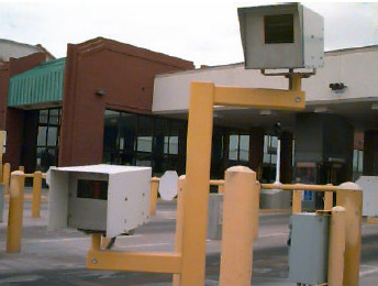
Figure 7. License Plate Reader at the Zaragoza Bridge, El Paso (Automobile Side)
2.6.8 Vehicle Matching
A vehicle matching system compares image patterns directly without the requirement to recognize symbols. This means that it does not "read" a license plate. It works by capturing the images of passing vehicles and "fingerprinting" each vehicle together with a date, time, and position stamp. A communications link transmits these fingerprints to an exit system, which stores them as entry fingerprints. The exit system also captures vehicle images and creates fingerprints, then matches them. This technique is used to determine travel time of vehicles that have been speeding, and then activates a license plate reader to document the violation and bill the vehicle owner.
A company that provides this technology claims that it:
- will work with any license plate style or type;
- does not need to be re-programmed if new plates are issued;
- is not affected by trailer hitches, license plate frames, etc.;
- uses more information than just plate characters;
- can perform matches on vehicles without visible license plates; and
- works whether the vehicle has a computer-readable license plate or not.
This product uses a laser ranger to detect passing vehicles, which triggers a camera. Vehicle images are captured by this advanced digital video camera, whose controls are constantly adjusted by a smart light sensor. This light sensor adjusts camera parameters for optimum license plate and vehicle contrast regardless of ambient illumination conditions. It decides when to turn nighttime illumination on or off. It uses a light flash that is filtered to be invisible to drivers and which illuminates the entire vehicle, not just the license plate.
Border Applications of Automatic Vehicle Identification Technology
Among the advantages, there is a very high probability of identification. There is also a portable version of this system available. It involves a trailer that positions an arm with the sensing technology equipment over two lanes of traffic. However, the portable version ideally needs a downlook angle from overhead to fingerprint moving trucks effectively. Among the disadvantages, Vehicle Matching would be a relatively expensive system for a travel time application.
previous | next