Comprehensive Truck Size and Weight Limits Study - Highway Safety and Truck Crash Comparative Analysis Technical Report
Appendix D: Models for the Vehicle Stability and Control Analysis
The basic configurations of the control and study vehicles were selected by the U.S. Department of Transportation. The number and length of trailers, the number and position of axles, and the maximum allowable gross vehicle weight were decided for the contractor team and were common across all analysis tasks.
Within this guidance, the USDOT study team developed simulation models for evaluating vehicle performance. The models consist of a set of properties (dimensions, weights, compliances, and so forth) that are entered in TruckSim® as a set of parameters.
This appendix documents the sources of the data that were used to construct the models and the decision processes for applying them.
Basic Vehicle Model
The model for the single-trailer control case was based on a model that was experimentally verified for a number of maneuvers in prior work. The other seven models were built by modifying this original model as necessary to, for example, add an axle or change the length of a trailer. Properties have been compared with industry values where possible, but the new models have not been separately verified.
Single-Trailer Models
The tandem-axle tractor model was based on a 2006 Volvo 6x4 model VNL64T630, and the tandem-axle trailer on a 1992 Fruehauf box trailer. The parameters for this configuration were obtained from a model developed for the National Highway Traffic Safety Administration (Rao et al. 2013b). That reference describes the measurements of the vehicle's properties and documents how they were modeled in TruckSim®. For both the tractor and trailer, there were measurements of mass and inertia, suspension compliance and geometry, tires, and brakes.
Although the parameters were obtained from previously published work, simulations were performed to compare the results with previously published validation work (Rao et al. 2013a) to ensure the model was properly implemented. Two maneuvers were used to verify the model, slowly increasing steer at constant speed and ramp steer with drop-throttle. Steering angle, longitudinal speed, lateral acceleration, and yaw rate all were compared for both maneuvers.
Payloads in the Single-Trailer Combinations
The payload in each of the single-trailer combinations consisted of blocks of equal height. Both blocks had uniform density and together they filled the 53-ft. floor area of the semitrailer. The relative densities and lengths of the two blocks were chosen to achieve the target axle loads in Table B3 of the Project Plan (Appendix B). The payloads in both the single- and multiple-trailer vehicles had a width of 99 in.
The starting point to determine the payload properties was the 97,000-lb., six-axle 3-S3 vehicle for Scenario 3. The relative densities of the two payload blocks and their relative sizes were chosen such that volume of the 53-ft trailer was completely filled. The densities of the two blocks were retained but their heights were reduced to produce the 91,000-lbs. gross vehicle weight of Scenario 2.
To maintain a reasonably uniform axle load on the five-axle combinations of the control single vehicle and Scenario 1, the densities of the two payload blocks were recalculated to move the center of gravity forward. Again, the payload height was reduced to decrease the gross vehicle weight from 88,000 lbs. to 80,000 lbs.
Axle weights in the empty and loaded conditions for all eight vehicles were measured by simulating a straight drive at 5 mph. The gross vehicle weights of the four single-trailer combinations were all within 0.5 percent of the target values.
Figure D1 shows the payload properties for all the single-trailer combinations. The size of payloads, dimensions and CG locations are not to scale.
Figure D1. Dimensions of Payloads on the Single-Trailer Combinations

Multi-Trailer Combination Models
The multi-trailer combination models were developed with a combination of available published data and TruckSim® default parameters. Suspension and brake parameters for all axles were retained from the experimentally verified values used for the single-trailer combinations. The tandem-axle tractor was also the same as the tractor used in the single-trailer combinations. Any properties that were unique to multi-trailer combinations such as the sprung masses and moments of inertia for the single axle tractor, 28-ft. trailer and 33-ft. trailer were obtained from TruckSim» defaults.
Trailer-to-Trailer Spacing for Multi-Trailer Combination
Figure D2 and Table D2 present the longitudinal positions of the axles and other key components of the models. Dimensions of the pintle hitch and dolly for multi-trailer combinations were based on industry standards (SAE International 2013 and SAE International 2014).
Figure D2. Trailer-to-Trailer Spacing Schematic
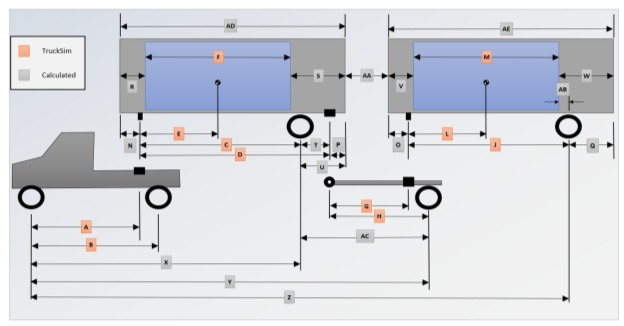
All dimensions are in inches.
Multi-Trailer Combination Payloads
Given the tare weights of the unloaded vehicle, computing the necessary payload masses to achieve the target total axle loads is straightforward. Only a single payload was needed in each trailer.
The controlling case for determining the payload density was the 33-ft. trailers in Scenario 4. A payload of approximately 700 lbs. per longitudinal ft. in the trailer brought the gross vehicle weight up to the allowed 80,000 lbs. This same payload density was put in the two 28-ft. trailers of the control double vehicle and the three 28-ft. trailers of Scenario 5. Adjustment was made to the payload floor area by dimensions "R" and "V" in Table D2 to achieve individual target axle loads as shown in Figure 4 of the main text.
The 129,000-lb. loading and nine-axle configuration of the Scenario 6 were sufficiently different from the other vehicles that payloads were applied to bring all axle loads close to their targets and the gross vehicle weight to within 0.1 percent of the allowed maximum.
Rao, S.J. et al. (2013a). "Validation of Real Time Hardware in the Loop Simulation for ESC Testing with a 6×4 Tractor and Trailer Models." SAE Paper 2013-01-0692.
Rao, S.J. et al. (2013b). "Modeling of a 6×4 Tractor and Trailers for Use in Real Time Hardware in the Loop Simulation for ESC Testing." SAE Paper 2013-01-0693.
SAE International (2014). Truck Tractor Semitrailer Interchange Coupling Dimensions. Surface Vehicle Information Report. J701
SAE International (2013) Connection and Accessory Locations for Towing Multiple Trailers - Truck and Bus. Surface Vehicle Recommended Practice. J849
previous | next