Appendix D. Example Application of NTCIP Standards
As an example of how NTCIP standards are applied, the following contains excerpts from Section 4, "Transportation Management Center Communications Specifications" from the FDOT draft specification for DMS devices titled Dynamic Message Sign Specifications for Limited-Access Facilities. The specification references specific NTCIP standards and the specific MIBs to be implemented for communication with the DMS field devices (to be deployed in Florida).
Dynamic Message Sign Specifications for Limited-Access Facilities
Version 5 (January 19, 2005)
This specification replaces the FDOT TERL Permanent Mount Dynamic Message Sign Minimum Specifications dated September 2001.
4. Transportation Management Center Communication Specifications
The sign controller shall be addressable by the TMC through the Ethernet communication network. Software shall comply with the NTCIP 1101 base standard (formerly the NEMA TS 3.2-1996 standard), including all amendments as published at the time the Request for Proposals (RFP) is released, and the NTCIP Simple Transportation Management Framework (STMF), and shall conform to Compliance Level 1. Software shall implement all mandatory objects as defined in the FDOT-standard Global MIB v01c in Appendix A of that document.4 Software shall implement all mandatory objects as defined in the FDOT-standard DMS MIB v01c in Appendix B of that document. Software shall implement all mandatory objects as defined in the FDOT-specific DMS MIB v01c in Appendix C of that document. The DMS shall comply with the NTCIP 1201 v01, 1203 v01, 2101 v01.19, 2103 v01.13, 2201 v01.14, 2202 v01.05, and 2301 v01.08 standards. Software may implement additional objects, but the additional objects shall not interfere with the standard operation of any mandatory objects.
Each DMS shall provide full, standardized range support for all objects required by these specifications unless otherwise detailed in the plans. The standardized range is defined by a size, range, or enumerated listing indicated in the object's syntax field and/or through descriptive text in the relevant standard object description field. The DMS maximum response time for any object or group of objects shall be 200 milliseconds unless otherwise indicated in the plans, or unless approved by the FDOT Traffic Engineering Research Laboratory (TERL). Deviances from the full ranges for objects are detailed below.
| Objects | Minimum project requirements |
|---|---|
| Maximum Event Log Configurations | 50 |
| Event Configuration Mode | 2, 3, and 4 |
| Maximum Event Log Size | 200 |
| Maximum Event Classes | 7 |
| Maximum Group Address | 1 |
| Objects | Minimum project requirements |
|---|---|
| Number of Fonts | 4 |
| Maximum Font Characters | 255 |
| Default Background Color | 0 |
| Default Foreground Color | 2, 7, 8, or 9 |
| Default Justification Line | 2, 3, 4 |
| Default Justification Page | 2, 3, 4 |
| DMS – Number of Permanent Messages | 0 |
| DMS – Maximum Changeable Messages | 50 |
| DMS – Maximum Volatile Messages | 0 |
| Nonvolatile Memory | 5 KB |
| DMS – Control Mode | 2, 3, 4, and 5 |
| Number of Action Table Entries | 15 |
| Number of Brightness Levels | 255 |
The software shall implement the tags (opening and closing where defined) of MULTI as detailed in Table 4.2 and as defined in the NTCIP 1203 standard.
| Opening Tag | Closing Tag | Explanation |
|---|---|---|
| cbx | |
Color – Background – The background color for a message. |
| cfx | |
Color – Foreground – The foreground color for a message. |
| fx,y | |
Field – The information to embed within a message that is based on data
from some device, such as a clock, calendar, temperature sensor, detector,
etc. The following field tag values (IDs) are REQUIRED to be supported:
1 – the time in a 12-hour format 2 – the time in a 24-hour format 4 – the ambient temperature in degrees Fahrenheit 7 – the day of the week 8 – the date of the month 9 – the month of the year 10 – the year in two digits 11 – the year in four digits |
| fltxoy | /fl | Flash – Activate flashing of the text; define the flash-on and flash-off times; and the flash order (i.e., on/off or off/on). |
| fox | |
Font – Selects a font number (as specified in the font table) for the message display. |
| jlx | |
Justification – Line – Specify line justification: left, center, right, or full. However, full justification is not required. |
| jpx | |
Justification – Page – Specify page justification: top, middle, or bottom placement. |
| mvtdw,s,r,text | Moving – Text – Specify the parameters of a horizontal moving (scrolling) text. | |
| nlx | |
New – Line – Specify the start of a new line. |
| np | |
New – Page – Specify the start of a new page. |
| ptxoy | |
Page – Time – Specify the page times (t = on , o = off). |
| scx | /sc | Spacing – Character – Specify the spacing between characters. |
| * The letters “x” and “y” are character placeholders, usually for numbers, that specify the tag parameter(s). See the NTCIP1203 standard and its amendments for further definitions. | ||
Refer to Sections 5.9 and 5 .10 contained herein as they relate to software licenses and intellectual property. All center-to-field device communications shall be nonproprietary.
4 Information on the DMS Management Information Base (MIB) is available online at http://www.dot.state.fl.us/trafficoperations/fdot_dms_mib_faq.htm
Each sign controller shall be provided with error detection and reporting features that will be used to guard against incomplete or inaccurate transmissions. These features shall include:
- Cyclic redundancy checking of all data received from the TMC, with positive acknowledgment for all valid transmissions
- Status monitoring for communication line malfunctions or breakages
- Content validation for all transmissions received for logic or data errors
The communication line circuits shall be point-to-point or multipoint, and shall be full duplex asynchronous data transmissions at the rate directed by the Engineer.
Each sign controller shall be assigned a unique address in the circuit that the sign is connected to. Where applicable, all data transmitted between the TMC and the sign controller shall be encoded using 1 start bit, 8 data bits, and 1 stop bit.
The following NTCIP standards are shown in the center-to-field (C2F) NTCIP DMS standards framework diagram below. Those that are compliance standards in the FDOT DMS specification are listed in bold print below and shown on the highlighted paths in the diagram.
- NTCIP 1101: Simple Transportation Management Framework (STMF).
- NTCIP 1102: Base Standard: Octet Encoding Rules (OER).
- NTCIP 1103: Simple Transportation Management Protocol (STMP).
- NTCIP 1201: Global Object Definitions.
- NTCIP 1203: NTCIP Object Definitions for Dynamic Message Signs (DMS).
- NTCIP 2101: Point to Multi-Point Protocol Using RS-232 Subnetwork Profile.
- NTCIP 2102: Subnet Profile for PMPP Over FSK modems.
- NTCIP 2103: Subnet Profile for Point-to-Point Protocol using RS 232.
- NTCIP 2104: Subnet Profile for Ethernet.
- NTCIP 2201: Transportation Transport Profile.
- NTCIP 2202: Internet (TCP/IP and UDP/IP) Transport Profile.
- NTCIP 2301: Application Profile for Simple Transportation Management Framework (STMF).
- NTCIP 2302: Application Profile for Trivial File Transfer Protocol.
- NTCIP 2303: Application Profile for File Transfer Protocol (FTP).
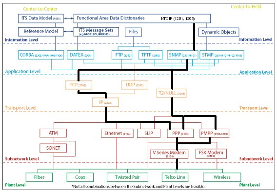
Figure D-1 C2F NTCIP DMS Standards Framework
Based on the NTCIP Standards specified in the FDOT DMS specification, it is clear that the desired DMS C2F communications implementation is intended to use SNMP at the application level, support TCP/IP or T2/NULL at the transport level, and use point-to-point or point-to-multi-point protocol using a RS-232 interface to a V series modem at the subnetwork level.
Previous | Next