Chapter 2. Fundamentals of Telecommunications
Page 3 of 3
Multiplexing
Multiplexing is the process of combining two or more information channels into a single transmission medium. There are a number of different standards that can be applied to the process. Many standards are common and are applied by manufacturers and carriers on a world-wide basis. This assures that a multiplexing protocol used in Japan can also be used in Brazil, Kansas, New York, or Tulsa.
This section will focus on two of the most common types of multiplexing – TDM (time division multiplexing), and PDM (packet division multiplexing. Additionally, this section will describe the primary multiplexing protocol in use in North America: T-1.
T-1 was the basic type of multiplexing scheme selected by Bell Labs for high capacity communication links. It is so pervasive in the world wide telephone network, that replacement protocols are just being introduced. A second type of multiplexing – Packet - will also be discussed, because this is now being used to support the conversion of the telephone networks from analog to digital. Packet multiplexing is used to support IP and Ethernet.
Time Division Multiplexing
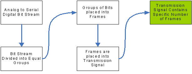
Time Division Multiplexing is a method of putting multiple data streams in a single communication channel, by separating it into many segments. Each segment is of a very short duration and always occurs at the same point in time within the main signal. In TDM, there is a direct relationship between the connections (ports) on the multiplexing hardware and the multiplexing protocol. The data for port number one of the multiplexer always falls within the same time period (time frame #1) – because the originating end multiplexer always places the data for each communication port at the same place.
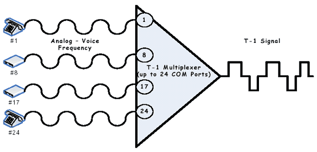
In time, the receiving end multiplexer is able to funnel data to the correct port. There is no data added to the bit stream to identify the data. With TDM, the general rule is "time slot (frame) one = communication port one". A T-1 multiplexer has 24 ports (one for each time slot). Therefore, time slot one = port one; time slot two = port two; etc. In a TDM transmission, each time slot is always present even if only one time slot actually has data. The bandwidth is always used.
Packet Division Multiplexing
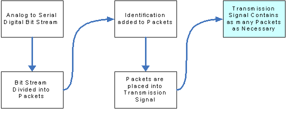
Packet Division Multiplexing (PDM) is a method of breaking the data into multiple groups. Each group is given an identity at the origination so that the multiplexer at the receiving end can assemble groups of data to re-create the information as it was originated. In theory, many information sources can be funneled through a single communication port on both ends. In some packet multiplexing schemes, the size of the packet – the amount of data included – can vary to provide greater throughput of information. With packet multiplexing, the bandwidth used never exceeds the total amount of data in all packets being transmitted. The PDM scheme is important because it is the basis for the new generation of broadband communication processes. Ethernet is an example of a transmission protocol that relies on packet division multiplexing.
TDM is excellent for supporting voice communications and broadcast quality video, because each service gets the amount of bandwidth required. PDM is excellent for data transmission because it only uses the bandwidth required and requires less hardware. The technologies of TDM and PDM have both been available for many years. TDM was more broadly deployed because it suited the requirement of the telephone companies to provide high quality voice communications. However, with recent advances in communication technology this is changing.
The following table provides a comparison of packet and time division multiplexing:
T-1 Communication Systems
T-1 Analog to Digital Conversion Process A voice signal is changed from analog to digital within a channel bank by two processes. First, the analog signal is sampled 8000 times each second. Each sample is converted to a discrete voltage level. Second, each voltage is converted to a binary code represented by an 8 bit word. Therefore, 8000 samples times 8 bits is 64,000 bits – a DS-0 communication channel. |
The T-1 based digital network has been under development for more than 40 years. During this time, a hierarchy of transmission levels has been implemented through a wide variety of equipment. The primary device is a channel bank which can be arranged to carry many different voice, analog data, or digital data signals. Port cards in the channel bank are used to support the type of inputs into the T-1. The most common are voice (POTS), and digital data (DDS).
A T-1 contains 24 signals (or channels). Each channel is represented by 8 bits, for a total of 192 bits within a single frame. A bit is added for management (synchronization, error checking, etc), and the result is a T-1 frame. Because the sampling rate of each channel is 8000 times per second, a T-1 contains 8000 frames, or 1,544,000 bits. In a TDM system, each channel is recognized within each frame at exactly the same point in time. That is – for example – channel one never appears in a channel five time slot.
This most common form of multiplexing is used primarily for voice channel services. In fact almost all P.O.T.S. and Special Service communication circuits are multiplexed for transport between Telephone Company Central Offices. Multiplexing (from the telephone company perspective) was developed to obtain efficiency in the use of the available communication cable plant. The telephone companies were able to provide services to more customers without the expensive installation of new communication cables.
There were a number of early attempts at providing an efficient multiplexing protocol; for voice based services, but the carriers had to consider the overall quality of the voice communication. Ultimately, the standard for "toll-grade" voice was set as the transmission of frequencies between 0 Hz and 4000 Hz.
The voice frequencies are digitized for multiplexing via a process that samples the frequencies at 8000 points in one cycle (Hz) in a period of one second. Each digital sample point is produced as an 8 bit character. Therefore, each voice channel uses 64,000 bits per second. Twenty-four voice channels are combined into a single multiplexed communication channel referred to as a T-1.
Because the telephone company needs to monitor and manage the T-1 circuit, it "steals" 8000 bits. A few bits are taken from each sample point, and the caller never notices a reduction in quality.
Most data transmission is accomplished using a dial-up modem. The modem converts the data output of a computer (or other device – traffic signal field controller, dynamic message sign, etc.) to a VF (voice frequency) signal. This signal is treated as if it were a P.O.T.S telephone call. The modem dials a telephone number associated with another modem and a connection is made via the switched voice network. The telephone network does not treat the call as if it were something special. In terms of T-1 multiplexing, it is treated as if it were a normal telephone call.
Multiplexing does reduce some of the overall quality of the transmission, but does not affect its usability. Unfortunately, each step in the process of getting data transmitted from one location to another can introduce a problem. Therefore, when troubleshooting, it is important to check every segment of the transmission path and all attached equipment – especially if the trouble cannot be found at either of the termination points. T-1 multiplexers are designed to convert analog signals to digital, therefore, data output by a computer must be converted to analog before being multiplexed.
In addition to dial-up data transmission, the telephone companies offer two additional services: 2/4 wire analog circuits (as mentioned above) and DDS (Digital Data Service). The 2/4 wire services are generally used for transmission rates of 9600 bits per second, or slower. DDS (originally offered for data rates from 2400 bits per second and higher) is used primarily for data transmitted at 56,000 bits per second. A DSU/CSU is required to condition a digital output from a computer to a format that will travel over telephone lines. Because the signal is no longer analog, a special interface card must be installed in the T-1 multiplexer (see below).
Transporting Digital Communications via an Analog Network
Whenever a digital signal is be transported via the public telephone network it must be "conditioned" for travel. This is because the basic wiring infrastructure was designed to transport an analog communication signal. Analog communication is accomplished by providing a variable electrical signal which varies as the frequency of a human speaking. Changes in volume and pitch are represented by a smooth flowing electrical current with positive and negative values. A dial-up modem converts your computer output to a series of analog tones which can be transported via the network in the same manner as a voice telephone call.
Digital signals are different. Data is represented by the presence, or absence of an electrical signal – "on or off". "On" represents 1, "off" represents 0. Electrical signals can have either a positive, or a negative value. The digital output of your computer must be converted to something that is compatible with the existing telephone network. A Data Service Unit (DSU) is used to convert the on/off electrical signal to something that looks like an analog signal. Electrical voltages representing 1 are given alternating positive and negative values. The momentary absence of an electrical signal is assigned a zero value. The DSU is normally used in conjunction with a Channel Service Unit (CSU). The CSU is used as a management tool to make certain that the communications link is performing to specification.
High Capacity Broadband Transmission
This section describes various high capacity and broadband transmission systems. When the telephone companies first deployed T-1 services, they called this "High Capacity" digital services. Video transmission for broadcast or conferencing used multiple T-1s, or multiple T-3 circuits. With the deregulation of telephone companies and the rise in demand for very high capacity, a new type of service was developed – broadband. As explained, T-1's are formatted by the telephone carriers, but large corporate users, government entities, and even the home user want un-formatted bandwidth to be available for a large number of services.
T-1/DS-1 & T-3/DS-3
T-1 and DS-1 services are fixed point-to-point systems, and dedicated to a single customer. These types of services are most often used to connect Traffic Operations Centers. They may also be used to bring the data and video images from a section of freeway back to a TOC.
DDS are digital voice channel equivalents as described previously and are used as a fixed point-to-point service. T-1 service is channelized to accommodate 24 DDS circuits.
The terms T-1 and DS-1 are often used interchangeably, but each is a distinctly different service provided by telephone companies and carriers. T-1 service is channelized with the carrier providing all multiplexing (channel banks) equipment. The customer is provided with 24 DS-0 interfaces. Each DS-0 interface has a maximum data capacity of 56 kbps (or can accommodate one voice circuit). The customer tells the carrier how to configure the local channel bank (multiplexer).
DS-1 service allows the customer to configure the high speed circuit. The customer provides (and is responsible for maintaining) all local equipment – multiplexer, and DSU/CSU. The carrier provides (and maintains) the transmission path. The customers can channelize the DS-1 to their own specifications as long as the bandwidth required does not exceed 1.536 mbps, and the DS-1 signal meets applicable AT&T, Bellcore (Telcordia) and ANSI standards (these standards are now maintained and available through Telcordia).
Customers may purchase fractional service to save money. In this case, they don't pay for a full T-1 or DS-1. However, the economies for this type of service are only realized for longer distances. The local loop (link) for Fractional T-1 is still charged at the full service rate.
T-3 and DS-3 services are essentially higher bandwidth variants of T-1 and DS-1. The T-3 provides either 28 T-1s or 28 DS-1s, and the DS-3 provides about 44 mbps of contiguous bandwidth. DS-3s are used for Distance Learning and broadcast quality video. They are also used in enterprise networks to connect major office centers.
T-1, DS-1, T-3, and DS-3 have the following characteristics:
- They are all private line services
- They are all provided on a fixed point-to-point basis
- Most users pay for the installation of the service
- Users pay a monthly fee based on distance – very large corporate customers are able to negotiate favorable rates for DS-1 and DS-3 services.
- Users pay a fixed monthly connection and maintenance fee
DSL
DSL (Digital Subscriber Loop) services are DS-1 and Fractional DS-1 variants that use existing P.O.T.S. service telephone lines to provide broadband services at a substantially lower cost. Local DS-1 service starts at $500 per month. Basic DSL service starts at less than $50 per month. The primary difference between the services is that DS-1 is setup as a private line system with fixed communication points. DSL service is typically used to provide broadband internet connectivity. Some carriers will create a "quasi" private circuit by linking two customer locations to a common Central Office. The primary advantage of DSL for the homeowner or small business is that it shares the existing telephone lines and it keeps the cost of installation at a much lower level.
DSL service has the following characteristics:
- Typically provided in an ADSL (Asymmetrical DSL) format with the link toward the customer (download) at a higher rate than the link toward the Internet (upload).
- DSL can be provided as SDSL (Symmetrical DSL) when the user needs to have equal bandwidth bi-directionally.
- DSL is a shared service. At peak use times, the available bandwidth is reduced. Many users have complained that they get better service via dial-up.
- DSL offerings start at 384 kbps/128 kbps and can rise to 6.0 mbps/6.0 mbps. (the monthly rates start at $30 and rise to $400.
- DSL can only be used when the customer is no more than 18,000 "wire feet" from the Serving Central Office. Best service is available when the customer is less than 12,000 "wire feet" distant.
- DSL is most often used to provide internet access.
SONET
SONET (Synchronous Optical Network) is the first fiber optic based digital transmission protocol/standard. The SONET format allows different types of transmission signal formats to be carried on one line as a uniform payload with network management. A single SONET channel will carry a mixture of basic voice, high and low speed data, video, and Ethernet. All of these signals will be unaffected by the fact that they are being transported as part of a SONET payload.
The SONET standard starts at the optical equivalent of DS-3. This is referred to as an OC-1 (Optical Carrier 1). The optical carrier includes all of the DS-3 data and network management overhead, plus a SONET network management overhead. In North America, the following SONET hierarchy is used: OC-3; OC-12; OC-48; OC-96; OC-192. The number indicates the total of DS-3 channel equivalents in the payload.
Within the payload, SONET network management allows for the shifting of DS-1 circuits. SONET is a point-to-point TDM system, but it has the ability to allow users to set up a multipoint distribution of DS-1s and DS-3s. Therefore, it is possible to direct a DS-1 from one location to many locations within the SONET network. The reader should note that SONET does not provide "bandwidth-on-demand". The routing of portions of the SONET payload to multiple points must be planned and built into a routing table.
A SONET network management program provides the ability to set up multiple routing plans. These plans can be executed as part of a program to restore service in the event of an outage in a portion of the network. Some early adopters of SONET attempted to use this feature to provide for "time-of-day" routing changes. Often users were disappointed with the results.
Normally, SONET is transmitted in groups of DS-3s (OC-3, OC-12, OC-48, etc). In this mode, the SONET payload is segmented within the DS-3. However, it is possible to combine DS-3s into a single channel. An OC-3C (concatenated) is a group of DS-3s combined into a single payload to allow for the total use of the OC-3 as a single data stream.
ATM
Asynchronous Transfer Mode (ATM) is a widely deployed communications backbone technology based on Packet Multiplexing. ATM is a data-link layer protocol that permits the integration of voice and data, and provides quality of service (QoS) capabilities. This standards-based transport medium is widely used for access to a wide-area (WAN) data communications networks. ATM nodes are sometimes called "Edge Devices". These Edge Devices facilitate telecommunications systems to send data, video and voice at high speeds.
ATM uses sophisticated network management features to allow carriers to guarantee quality of service. Sometimes referred to as cell relay, ATM uses short, fixed-length packets called cells for transport. Information is divided among these cells, transmitted and then re-assembled at their final destination. Carriers also offer "Frame Relay" service for general data requirements that can accept a variable packet or frame size. Frame Relay systems use variable cell (packets) based on the amount of data to be transmitted. This allows for a more efficient use of a data communications network.
ATM services are offered by most carriers. A number of DOTs are using this type of service – especially in metropolitan areas – to connect CCTV cameras (using compressed video), traffic signal systems, and dynamic message signs to Traffic Operations Centers. The stable packet size is well suited for video transmission. ATM is generally not used by telephone companies for toll grade voice, although its stable packet size was developed to meet requirements for voice service.
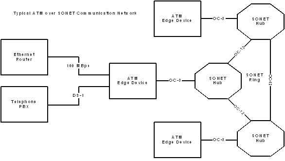
In a WAN (wide area network), ATM is most often used as an "edge" transport protocol. ATM devices typically have ports that allow for easy connectivity of legacy systems and the newer communications systems. In a private (or enterprise) network, as shown in figure 2-12, ATM is effectively used for voice and video transport as well as data.
ATM has fixed-length "cells" of 53 bytes in length in contrast to Frame Relay and Ethernet's variable-length "frames." The size of cell that represents a compromise between the large frame requirements of data transmission and the relatively small needs of voice calls. By catering to both forms of network traffic, ATM can be used to handle an end user's entire networking needs, removing the need for separate data and voice networks. The performance, however, can also be compromised, and the network may not be as efficient as dedicated networks for each service. ATM systems usually require DS-1 circuits, but can be made to work in a lower speed environment.
ATM does have a reputation for being difficult to interface to an existing network. However, competent network technicians can usually overcome most difficulties. Missouri DOT is using an ATM based network for its ATMS.
FDM
Frequency Division Multiplexing (FDM) is used when large groups of analog (voice or video) channels are required. The available frequency bandwidth on an individual communications link is simply divided into a number of sub-channels, each carrying a different communication session. A typical voice channel requires at least 3 kHz of bandwidth. If the basic communication link is capable of carrying 3 megahertz of bandwidth, approximately 1000 voice channels could be carried between two points. Frequency Division Multiplexing was used to carry several low speed (less than 2400 bits per second) data channels between two points, but was abandoned in favor of TDM which has an ability to carry more data channels with more capacity over greater distances with fewer engineering problems.
Many older Cable TV systems use FDM to carry multiple channels to customers. This type of system was used by Freeway Management Systems to carry video over coaxial cable. However, most coaxial systems have been replaced by fiber optic systems. Fiber has a greater bandwidth capability than coaxial cable, or twisted pair. The FDM scheme allows for multiple broadband video channels to be carried over a single strand of fiber.
WDM – CWDM & DWDM
Wave Division Multiplexing (WDM) is an optical variant of FDM. A beam of light is divided into segments called lambdas. The Greek letter Lambda (λ) is used to represent the wave channels. These lambdas are actually different colors of light. Because a wavelength is inversely proportional to frequency WDM is logically equivalent to FDM.
Light transmitted over a fiber is normally a group of frequencies that can be used to create a single communication channel, or multiple channels. The frequency group can be broken into several sub groups. The LASER output of a multiplexer is "tuned" to a specific set of frequencies to form a single communication channel. These channels are then transmitted with other frequency groups via a wave division multiplexer. Unlike FDM, the information sent via the frequency groups is digital.
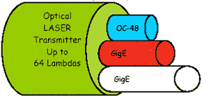
Two variables of WDM are used, CWDM (coarse wave division multiplexing) and DWDM (dense wave division multiplexing). DWDM systems can carry as many as 64 channels at 2.5 gigabits per second per channel over a pair of fibers. Each DWDM lambda is equal to one OC-48 (48 DS-3s), or one Gigabit Ethernet channel (future systems will allow 2 GigE channels per lambda).
Ethernet
Ethernet is a packet based network protocol, invented by the Xerox Corporation, in 1973, to provide connectivity between many computers and one printer. Ethernet was designed to work over a coaxial cable that was daisy-chained (shared) among many devices. The original Xerox design has evolved into an IEEE series of standards (802.XXX) with many variations that include 10Base-T, Fast-Ethernet (100Base-T), and GigE (Gigabit Ethernet).
The Ethernet system consists of three basic elements:
- The physical medium used to carry Ethernet signals between computers,
- A set of medium access control (MAC) rules embedded in each Ethernet interface that allows multiple computers to fairly arbitrate access to the shared Ethernet channel,
- An Ethernet frame that consists of a standardized set of bits used to carry data over the system.
The most current configurations use twisted pair with devices networked in a star configuration. Each device has a direct connection to an Ethernet hub, or router, or switch. This system then provides each user with a connection to a printer, file server, another user computer (peer), or any other device on the network.
Ethernet works by setting up a very broadband connection to allow packets of data to move at high speed through a network. This assures that many users can communicate with devices in a timely manner. The Ethernet is shared, and under normal circumstances, no one user has exclusivity.
Note: When Ethernet is used to connect only two devices via a common communication channel CSMA is not used. This is because the two devices can coordinate communication so that one does not interfere with the other. This type of system can be used to transmit broadband video over long distances to take advantage of the bandwidth and economics of using Ethernet. Freeway Management Systems using incident detection CCTV cameras may use this type of arrangement to facilitate Video over IP. This allows video from the field to be transported to the TCC for further distribution. |
Traditional Ethernet networks of the 1990s used a protocol called CSMA/CD (carrier sense multiple access/collision detection). In this arrangement, the transmitting device looks at the network to determine if other devices are transmitting. The device "senses" the presence of a carrier. If no carrier is present, it proceeds with the transmission. The CSMA protocol is not perfect, hence the need for Collision Detection. Occasionally, more than one device transmits simultaneously and creates a "call collision". If the originating device does not receive an acknowledgement from the receiving device, it simply retransmits the information (not as part of the Ethernet protocol, but part of an application protocol). In an office environment, where users are trying to access a printer, or a file-server, this is normally not a problem. Most users are not aware of any significant delays. In this arrangement all devices are wired to the network through a "hub". The hub provides a central meeting point for all devices and users on the network, but has very little intelligence for managing activity on the network. In fact all communications on the network are sent to all devices on the network.
Each Ethernet-equipped computer, also known as a station, operates independently of all other stations on the network: there is no central controller. All stations attached to an Ethernet are connected to a shared signaling system, also called the medium. Ethernet signals are transmitted serially, one bit at a time, over the shared signal channel to every attached station. To send data, a station first listens to the channel, and when the channel is idle the station transmits its data in the form of an Ethernet frame, or packet.
After each frame transmission, all stations on the network must contend equally for the next frame transmission opportunity. This ensures that access to the network channel is fair, and that no single station can lock out the other stations. Access to the shared channel is determined by the medium access control (MAC) mechanism embedded in the Ethernet interface located in each station. The medium access control mechanism is based on a system called Carrier Sense Multiple Access with Collision Detection (CSMA/CD).
Modern networks still use CSMA/CD, but are managed by routers and switches. Routers are not actually Ethernet devices – they operate at layer 3 of the OSI protocol stack. The router is able to manage the flow of data between devices and has the intelligence to route information between specific devices. A request to view a file from an individual computer is routed to the specific file server storing the information. None of the other computers on the network see the data request. However, the router will simply route the request, it won't manage several users trying to access the same file server simultaneously.
Management of users in a network is accomplished by a Switch. The Switch has the intelligence and computing "horsepower" to manage users and allocate bandwidth. A Switch can be set to block some users from the system based on various factors, such as priority and time-of-day requirements.
Following is a description of the most commonly used Ethernet protocols:
- 10Base-T was the most commonly used variant (as this handbook was being developed, 100Base-T was most common, with GigE catching on fast). This is typically run over twisted pair copper and is adequate for most small office data communication requirements.
- Fast Ethernet or 100Base-T can be run over the same twisted pair infrastructure. The 10Base-T protocol allows for a maximum throughput of 10 megabits of data and the 100Base-T allows 100 megabits of data throughput. However, various factors keep these systems from exceeding more than 70 percent of stated capacity. Chief among these problems is overloading of the number of users and the condition of the wired infrastructure.
- 100Base-TX is a two twisted copper pair (4 wire) transmission standard. Identical to 10Base-T, it is also referred to as "fast Ethernet", and provides 100 Mbps throughput.
- 100Base-FX is a fiber optic transmission standard for Local Area Networks.
- GigE (gigabit Ethernet) is a very high bandwidth service (One gigabit per second) and is being deployed in many large office networks. In addition to allowing more users onto the network, GigE is capable of facilitating video between desktops, and desktop to desktop conferencing between users. GigE is also the preferred communications protocol for linking one office building to another. Metropolitan Networks (MAN) using DWDM facilitate a "real-time" GigE link. IT departments can create a storage area network (SAN) to link together many databases. Large financial institutions connect locations in a region to facilitate electronic commerce using DWDM and GigE. Many telephone carriers are beginning to add GigE services to their network offerings.
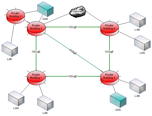
- 10GigE protocols and standards are being developed by IEEE under 802.3ae and 802.3AK. The 10GigE standards are being developed to use the protocol for broadband metropolitan area network (MAN) connectivity. At this time, there is no intention to use the standard to support desktop applications, however, all things change. 10GigE systems will be deployed using fiber optic transmission networks. Following is an example of a 10GigE Network.
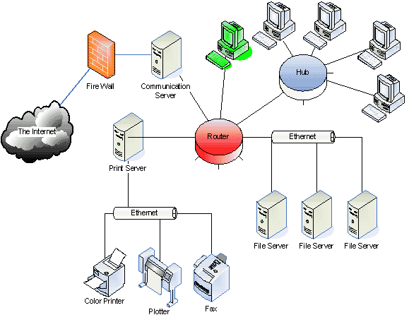
Because most of these networks are deployed in office buildings, the twisted pair cables tend to be run close to interference – causing electrical fixtures. The drawing shows a typical LAN for a small office. Notice that most of the office computers are connected via a hub, and that the printers, and communications services are connected via dedicated servers. This is simply one type of network that can be established using Ethernet. In very small offices, every device can be directly connected to a router. Large corporations will network several routers. The actual network configuration is based on completing a requirements document (see chapter 4). In this system every computer has access to every device, but the router can be programmed to restrict access based on the unique identity of each computer work station.
Figure 2-15 provides a look at how multiple building networks are connected via a metropolitan area network (MAN) Notice that there is one primary router in each building connected to a 10GigE network – each building is a node on the network. The common basis of Ethernet protocols provides an easy expansion path. The system shown is actually a network of networks.
Conclusions
The design of telecommunications systems is an iterative process. Each piece of a system is dependent upon the others. A simple example of this dependency can be found in the use of a modem. Basic modems rely on the cables that connect them to a computer (a serial cable) and the twisted-pair cable that connects them to a telephone network. Each of these elements is dependent upon the other to provide a working system. These types of dependencies can be found in all telecommunications systems. This chapter was organized to provide basic information about individual elements and their relationships. Recognition of these relationships will help to provide an effective design of a telecommunications network.
