Systems Engineering for Intelligent Transportation Systems
Systems Engineering for Intelligent Transportation Systems
This document is intended to help you understand how systems engineering can be used throughout the ITS project life cycle. Chapters 4 and 5 present two different types of processes that support systems engineering:
Relationship to Traditional Transportation Processes
ITS projects are identified and funded through transportation planning and programming/budgeting processes in each state, planning region (e.g., metropolitan planning area), and agency. The "V" diagram and the systems engineering process begin once a need for an ITS project has been identified. The early steps in the "V" define the project scope and determine the feasibility and acceptability as well as the costs and benefits of the project. These early steps actually support planning and programming/budgeting since they are intended to identify high-level risks, benefits, and costs and to determine if the ITS project is a good investment. The latter steps support project implementation, then transition into operations and maintenance, changes and upgrades, and ultimate retirement or replacement of the system. (The systems engineering "V" is placed in context with the traditional transportation project life cycle in Section 6.1.)
Technical Documentation
Each step of the process that is described in this chapter results in one or more technical outputs. This documentation is used in subsequent steps in the process and provides a critical documentation trail for the project. The documentation that is discussed in this chapter is identified in Table 1, which provides a bird's-eye view of where it fits in the "V". Several resources provide good descriptions and templates for this documentation.7 Note that not every ITS project will require every document listed in the table. (More information on tailoring is provided later in this chapter and in Section 6.2.3.)
About the Examples
This chapter is illustrated with real examples that show how different agencies have used the systems engineering process for their ITS projects. These real examples aren't perfect and shouldn't be taken as the only approach, or even the best approach, for accomplishing a particular step. As time goes by and we gain experience using systems engineering on ITS projects, many more examples will become available.
Table 1: Technical Documentation in the "V" Systems Engineering Process
| Documentation | Chapter / Process Step | 4.1 Using the Regional ITS Architecture | 4.2 Feasibility Study / Concept Exploration | 4.3 Concept of Operations | 4.4 System Requirements | 4.5 System Design | 4.6 SW/HW Development & Testing | 4.7 Integration & Verification | 4.8 Initial Deployment | 4.9 System Validation | 4.10 Operations and Maintenance | 4.11 Retirement / Replacement |
|---|---|---|---|---|---|---|---|---|---|---|---|---|
| Relevant portion of Reg ITS Arch | C | U | U | U | ||||||||
| Feasibility Study | C | U | ||||||||||
| Concept of Operations | C | U | ||||||||||
| System Validation Plan | C | U | ||||||||||
| System Requirements Document | C | U | U | U | U | U | U | U | ||||
| System Verification Plan | C | U | ||||||||||
| Traceability Matrix | C | U | U | U | U | |||||||
| System Acceptance Plan | C | U | ||||||||||
| High-Level (Architectural) Design | CU | U | ||||||||||
| Detailed Design Specifications | C | U | ||||||||||
| Interface Specifications | C | U | U | |||||||||
| Subsystem Verification Plans | C | U | ||||||||||
| Integration Plan | C | U | ||||||||||
| Subsystem Acceptance Plan | C | U | ||||||||||
| Unit/Device Test Plan | C | U | ||||||||||
| SW/HW Development Plans | CU | |||||||||||
| Verification Procedures | CU | |||||||||||
| Delivery & Installation Plan | CU | |||||||||||
| Transition Plan | CU | |||||||||||
| O&M Plan and Procedures | C | U | ||||||||||
| System Validation Procedures | CU | |||||||||||
| System Retirement Plan | CU | |||||||||||
| C: Create documentation U: Primary Use/Update of the documentation | ||||||||||||
 Using the Regional ITS
Architecture
Using the Regional ITS
ArchitectureIn this step: The portion of the regional ITS architecture that is related to the project is identified. Other artifacts of the planning and programming processes that are relevant to the project are collected and used as a starting point for project development. This is the first step in defining your ITS project.
| OBJECTIVES |
|
|---|---|
| INPUT
Sources of Information |
|
| PROCESS
Key Activities |
|
| OUTPUT
Process Results |
|
| Review
Proceed only if you have: |
|
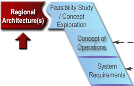
The regional ITS architecture provides a good starting point for systems engineering analyses that are performed during ITS project development. It provides region-level information that can be used and expanded in project development.
When an ITS project is initiated, there is a natural tendency to focus on the programmatic and technical details and to lose sight of the broader regional context. Using the regional ITS architecture as a basis for project implementation provides this regional context as shown in Figure 8. It provides each project sponsor with the opportunity to view their project in the context of surrounding systems. It also prompts the sponsor to think about how the project fits within the overall transportation vision for the region. Finally, it identifies the integration opportunities that should be considered and provides a head start for the systems engineering analysis.
Figure 8: Regional ITS Architecture Framework for Integration
 The regional
ITS architecture is a tool that is used in transportation planning,
programming, and project implementation for ITS. It is a framework for
institutional agreement and technical integration for ITS projects and is the
place to start when defining the basic scope of a project.
The regional
ITS architecture is a tool that is used in transportation planning,
programming, and project implementation for ITS. It is a framework for
institutional agreement and technical integration for ITS projects and is the
place to start when defining the basic scope of a project.
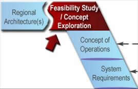
The regional ITS architecture is the first step in the "V" because the best opportunity for its use is at the beginning of the development process. The architecture is most valuable as a scoping tool that allows a project to be broadly defined and shown in a regional context. The regional ITS architecture step and the concept exploration step that is described in the next section may iterate since different concepts may have different architecture mappings. The initial architecture mapping may continue to be refined and used as the Concept of Operations and system requirements are developed.
 The
Regional ITS Architecture Guidance Document provides detailed guidance for
regional ITS architecture development, use, and maintenance. (Version 2 of
this document provides detailed guidance for using a regional ITS architecture
to support project implementation.)
The
Regional ITS Architecture Guidance Document provides detailed guidance for
regional ITS architecture development, use, and maintenance. (Version 2 of
this document provides detailed guidance for using a regional ITS architecture
to support project implementation.)
Initial use of the regional ITS architecture requires a few basic activities: locating the right architecture, identifying the portion of the architecture that applies to your project, and notifying the architecture maintainer of any required regional architecture changes. None of these tasks is particularly time consuming – the basic extraction of information can be done in an afternoon, even for a fairly complex project, if you are knowledgeable about the regional ITS architecture. Of course, it can be time consuming to climb the learning curve, and coordinating and building consensus on the scope of the project will require time and effort. Each of the key activities is described in the following paragraphs.
In the event that no regional ITS architecture exists at the time that an ITS project is initiated, coordinate with the FHWA Division/FTA Regional Office on starting a regional ITS architecture effort. In the interim, a project-level architecture should be developed based on the National ITS Architecture8 to support the ITS project.
 The systems engineering analysis
requirements identified in FHWA Rule 940.11/FTA Policy Section VI require
identification of the portion of the regional ITS architecture that is
implemented by each ITS project that uses federal funds. If a regional ITS
architecture does not exist, then the portion of the National ITS Architecture
that will be implemented by the project must be identified.
The systems engineering analysis
requirements identified in FHWA Rule 940.11/FTA Policy Section VI require
identification of the portion of the regional ITS architecture that is
implemented by each ITS project that uses federal funds. If a regional ITS
architecture does not exist, then the portion of the National ITS Architecture
that will be implemented by the project must be identified.
 You
should build consensus around the fundamental project scope decisions that are
made as the relevant portions of the regional ITS architecture are identified.
One good approach is to create a context diagram that shows the ITS system to
be implemented in the middle of the diagram surrounded by all other potentially
interfacing systems in the region. For example, Figure 9 is a context diagram
for the MaineDOT Communications Center. A context diagram can be used to
discuss integration opportunities that should be considered in this project and
in future projects. A discussion like this puts the ITS project in context and
raises awareness of future ITS integration opportunities. It also may
highlight regional ITS architecture issues that should be addressed.
You
should build consensus around the fundamental project scope decisions that are
made as the relevant portions of the regional ITS architecture are identified.
One good approach is to create a context diagram that shows the ITS system to
be implemented in the middle of the diagram surrounded by all other potentially
interfacing systems in the region. For example, Figure 9 is a context diagram
for the MaineDOT Communications Center. A context diagram can be used to
discuss integration opportunities that should be considered in this project and
in future projects. A discussion like this puts the ITS project in context and
raises awareness of future ITS integration opportunities. It also may
highlight regional ITS architecture issues that should be addressed.
In almost every case, the regional ITS architecture will identify potential integration opportunities that will not be included in the current project. Specific integration options may be deferred for many reasons – agencies on both sides of the interface may not be ready, there may not be sufficient funding or time available to implement everything, supporting infrastructure may not yet be completed, a necessary standard may not be available, implementing too much at once may incur too much complexity/risk, etc.
Even if they are deferred, it is important to account for future integration options in the current project design. The ultimate goal is to make ITS deployment as economical as possible by considering how this project will support future projects over time. To support this objective, future integration options that may impact the project design should be identified and considered in the project development. For example, additional stakeholders may be involved in the current project to ensure that future interface requirements are identified and factored into the current project design.
Each
region should define a mechanism that allows the project team to provide
comments on the architecture with minimal time investment. Project teams that
use the architecture will be among the most significant sources for regional
ITS architecture maintenance changes, and the region should strive to
facilitate this feedback. If your region does not have such a mechanism, consult
the Regional ITS Architecture Guidance Document for more information on
facilitating architecture use and maintenance in your region.
The first output of this step is the subset of the regional ITS architecture for the ITS project. While the Rule/Policy requires a subset of the regional ITS architecture to be identified, it does not define the components that should be included. You should consult local guidelines or requirements to help make this determination. In most cases, the following components will precisely define the scope of the project: (1) stakeholders, (2) inventory elements, (3) functional requirements, and (4) information flows.
These four components define the system(s) that will be created or impacted by the project, the affected stakeholders, the functionality that will be implemented, and the interfaces that will be added or updated. Other components may be identified, including market packages, roles and responsibilities, relevant ITS standards, and agreements. For very large ITS projects, this might be several pages of information. For a small ITS project, this might fit on a single page. The information that is extracted will actually be used in the concept exploration, Concept of Operations, requirements, and design steps that follow.
 The Turbo
Architecture software tool can be used to quickly and accurately define an ITS
project architecture if the regional ITS architecture was developed with
Turbo. Turbo Architecture can be used to generate diagrams and reports that fully
document the portion of the regional ITS architecture that will be implemented
by the project. Turbo Architecture can also be used to develop a project ITS
architecture based on the National ITS Architecture if a regional ITS
architecture does not exist. The Turbo Architecture software can be obtained
from McTrans by visiting their website at http://www-mctrans.ce.ufl.edu/featured/turbo/.
The Turbo
Architecture software tool can be used to quickly and accurately define an ITS
project architecture if the regional ITS architecture was developed with
Turbo. Turbo Architecture can be used to generate diagrams and reports that fully
document the portion of the regional ITS architecture that will be implemented
by the project. Turbo Architecture can also be used to develop a project ITS
architecture based on the National ITS Architecture if a regional ITS
architecture does not exist. The Turbo Architecture software can be obtained
from McTrans by visiting their website at http://www-mctrans.ce.ufl.edu/featured/turbo/.
If you don't
find what you need in the regional ITS architecture, then you should add the
missing or changed items to your architecture subset and highlight them so it
is clear what you changed. For example, if there is a system in your project
that is not represented in the regional ITS architecture, add it to your
architecture subset and highlight it. The highlighted changes serve two
purposes: they allow you to move forward with an augmented architecture subset
that you can use in the next steps of the process, and they provide the basis
for your feedback for regional ITS architecture maintenance.
The second output of this step – feedback to the regional ITS architecture maintenance team – is just as important as the first output. Submit any recommended changes using the mechanism defined for your region in the regional ITS architecture maintenance plan.
The subset of the regional ITS architecture that is included in the project can be shown in a series of simple tables and/or a diagram from Turbo Architecture, as shown in Figure 9. This figure identifies the inventory elements and interfaces that will be implemented by a MaineDOT Dynamic Message Sign (DMS) project in which several signs will be installed in Portland, Maine, along with a central control system with interfaces to a number of other centers. Functional requirements that are relevant to the project were also extracted, as shown in Table 2.
Figure 9: Example: MaineDOT DMS Project Architecture Subset
Table 2: MaineDOT DMS Project Functional Requirements (Partial List)
| Element | Functional Area | ID | Requirement |
|---|---|---|---|
| MaineDOT Communications Center | TMC Traffic Information Dissemination | 1 | The Center shall remotely control DMS for dissemination of traffic and other information to drivers. |
| MaineDOT Communications Center | TMC Traffic Information Dissemination | 3 | The Center shall collect operational status for the driver information systems equipment (DMS, HAR, etc.). |
| MaineDOT Communications Center | TMC Traffic Information Dissemination | 4 | The Center shall collect fault data for the driver information systems equipment (DMS, HAR, etc.) for repair. |
 In
this step: A business case is made for the project.
Technical, economic, and political feasibility is assessed; benefits and costs
are estimated; and key risks are identified. Alternative concepts for meeting
the project's purpose and need are explored, and the superior concept is
selected and justified using trade study techniques.
In
this step: A business case is made for the project.
Technical, economic, and political feasibility is assessed; benefits and costs
are estimated; and key risks are identified. Alternative concepts for meeting
the project's purpose and need are explored, and the superior concept is
selected and justified using trade study techniques.
| OBJECTIVES |
|
|---|---|
| INPUT
Sources of Information |
|
| PROCESS
Key Activities |
|
| OUTPUT
Process Results |
|
| Review
Proceed only if you have: |
|
In this step, the proposed ITS project is assessed to determine whether it is technically, economically, and operationally viable. Major concept alternatives are considered, and the most viable option is selected and justified. While the concept exploration should be at a fairly high level at this early stage, enough technical detail must be included to show that the proposed concept is workable and realistic. The feasibility study provides a basis for understanding and agreement among project decision makers – project management, executive management, and any external agencies that must support the project, such as a regional planning commission.
The
Rule/Policy requires the systems engineering analysis to include an analysis of
alternative system configurations and technology options. The focus of this
Rule/Policy requirement is on design decisions that are made later in the
process, but a fundamental analysis of basic systems configurations is
performed in this step.
It is easy
to confuse the concept exploration that is performed in this step with the
Concept of Operations that is developed in the next step. Concept
exploration is a broad assessment of fundamentally different alternatives –
for example, a new electronic toll facility versus additional conventional
lanes. The alternatives would have dramatically different concepts of
operations, so it is important to select a proposed concept before developing a
Concept of Operations. Different alternatives may also have different regional
ITS architecture mappings, so this step may iterate with the previous regional
ITS architecture step.
The process is driven by the project vision, goals, and objectives, and by the needs for the project that were identified through the transportation planning process. It starts by identifying a broad range of potential concepts that satisfy the project need(s). The concepts are compared relative to measures that assess the relative benefits, costs, and risks of each alternative. Project stakeholders must be involved to establish the evaluation criteria, verify that all viable alternative concepts are considered, and make sure there is consensus on the selected alternative. The recommendations provide a documented rationale for the selected project approach and an assessment of its feasibility. The process is identical to a feasibility study done for large roadway and transit projects.
The alternatives analysis that is performed during a feasibility analysis uses a basic trade study technique, shown in Figure 10, that will be repeated many times during the project life cycle. At this early concept exploration step, the alternatives are fundamental choices, such as to maintain the existing facility ("do nothing"), build a new road, or add ITS technology to the existing facility. During design, the alternatives are design decisions, such as whether signs should be located at location A, B, or C. During construction, alternatives may have to do with optimizing closures while the work is performed. At each step, a set of alternatives is identified and analyzed from technical, economic, and operational perspectives.
Figure 10: Concept Exploration Uses Basic Trade Study Techniques
 A
feasibility study should be conducted only when a broad analysis is needed
before the commitment of development resources. Some states require a
feasibility study for certain ITS projects. A feasibility study is typically
not required for smaller, incremental ITS projects where there are not
fundamentally different approaches for implementation and where feasibility is
not in question – for example, a project that adds DMS to an existing system.
In other cases, a broad exploration of alternatives is not warranted but a
cost-benefit study is needed to make the business case for the project.
A
feasibility study should be conducted only when a broad analysis is needed
before the commitment of development resources. Some states require a
feasibility study for certain ITS projects. A feasibility study is typically
not required for smaller, incremental ITS projects where there are not
fundamentally different approaches for implementation and where feasibility is
not in question – for example, a project that adds DMS to an existing system.
In other cases, a broad exploration of alternatives is not warranted but a
cost-benefit study is needed to make the business case for the project.
Here at the very beginning of project development, the unknowns will certainly outnumber the knowns. Without a Concept of Operations or requirements, many assumptions will have to be made. It is important to educate the group performing this assessment on the concept exploration process and to set a schedule – otherwise, this stage could be an open-ended process since there's always something new over the horizon. The process activities are:
Based on the statement of the problem, establish cost constraints and any other constraints that will be used to limit the acceptable alternatives. Determine how success will be measured – the degree to which the project will solve the stated problem or realize the identified opportunity. These measures should be included in the criteria that will be used to evaluate the alternative concepts. Also, do a preliminary risk analysis to identify issues and obstacles that may affect the project, and develop evaluation criteria that will measure the sensitivity of each candidate solution to each of the risks.
It is
a good idea to define evaluation criteria before alternative concepts are
enumerated. By developing the criteria first, you reduce the risk of
intuitively settling on an alternative and then subconsciously biasing the
criteria toward the preferred alternative. It is important to develop the
criteria so that they are not preferential to one of the concepts.
If you find that you are identifying specific products or vendors as the alternative solutions, you are being too specific. A trade comparison of products or vendors occurs much later in the process based on defined requirements during design. The alternatives here should be high-level concepts – for example, instrumentation with traffic detectors versus use of traffic probes to support traffic data collection for a corridor. Alternatives may also reflect life-cycle options, such as leased versus owned equipment, contracted versus in-house staffing, etc. You may have to establish a basic architecture and a minimal strawman design to support the analysis, but do no more than is necessary to support the evaluation.
 A
common pitfall in developing a concept exploration or any trade study
comparison is the premature selection of an alternative early in the study
process. Be sure to keep an open mind and spend enough time on all viable
options. If only one of the alternatives is defined in detail in a concept
exploration, it creates the appearance that the other alternatives were not
earnestly considered or explored.
A
common pitfall in developing a concept exploration or any trade study
comparison is the premature selection of an alternative early in the study
process. Be sure to keep an open mind and spend enough time on all viable
options. If only one of the alternatives is defined in detail in a concept
exploration, it creates the appearance that the other alternatives were not
earnestly considered or explored.
A number of tools support cost-benefit analysis for ITS projects:
The ITS Costs database
contains estimates that can be used for policy analysis and cost-benefit
analysis. It contains unit cost estimates for more than 200 ITS technologies
as well as system costs for selected ITS deployments. (The unit cost database
is available online and as an Excel spreadsheet at http://www.itscosts.its.dot.gov.)The ITS Benefits
database contains information regarding the impacts of ITS projects on the
operation of the surface transportation system. The ITS Benefits website
provides an online and Excel spreadsheet version of this database as well as
several other documents pertaining to ITS benefits. (See http://www.itsbenefits.its.dot.gov.)The ITS Deployment
Analysis System (IDAS) is software developed by the Federal Highway
Administration that can be used to estimate the benefits and costs of ITS
investments, which are either alternatives to or enhancements of traditional
highway and transit infrastructure. IDAS can currently predict relative costs
and benefits for more than 60 types of ITS investments. (See http://idas.camsys.com/.)SCRITS (SCReening for
ITS) is a spreadsheet analysis tool for estimating the user benefits of ITS. It
is intended as a sketch- or screening-level analysis tool for allowing
practitioners to obtain an initial indication of the possible benefits of
various ITS applications. (For more information, see https://www.fhwa.dot.gov/steam/scrits.htm.)While
it is best to do a complete analysis of every alternative, sometimes the sheer
number of alternatives makes this thorough approach impractical. One common
practice is to apply the evaluation criteria in stages, weeding out the
alternatives that don't meet the fundamental criteria so that the more
detailed, time-consuming analysis is performed on only a few of the most viable
alternatives. The evaluation should be validated by reviewing the analysis
with stakeholders who may have reasonable objections to certain assumptions and
alternatives.
Remember your audience when writing a feasibility study; this study
makes a business case primarily for a management audience. Any feature of the
study that prevents the reader from assimilating the costs and benefits and the
associated risks of each alternative solution as briefly, completely, and
painlessly as possible reduces the effectiveness of the study for the audience.
Several review cycles may be required for the feasibility study. First, the document should be circulated among the project team to make sure that there is buy-in. Then an updated draft should be distributed to internal management and other organizations for approval.
The feasibility study establishes the business case for investment in a project by defining the reasons for undertaking the project and analyzing its costs and benefits. Different organizations and different projects will have different requirements, but a feasibility study should contain, at a minimum, the following:
Identification of Alternatives – Transportation Planning Studies
Feasibility studies that examine alternative concepts are frequently done for large transportation projects as part of corridor studies, major investment studies, and environmental analysis reports. The ITS option(s) in these studies often compete with traditional capital improvement options; hybrid options, which include a mix of technology and traditional capital improvements, are also considered.
For example, a congested corridor in Collin County, Texas, was the subject of a feasibility study report (FSR)9 that was prepared by representatives from the North Central Texas Council of Governments and affected agencies. This FSR examined the following alternatives: (1) do nothing, (2) build a new freeway, (3) build a toll road with electronic collection (two alternatives), and (4) build managed lanes. One summary table that compared the traffic volumes supported by the different alternatives is shown in Table 3. Supported traffic volumes, estimated capital costs, and potential revenue generation were used to compare the alternatives. The analysis favored the electronic toll alternatives.
Broad alternatives analyses like these are included in many planning studies.
Table 3: Comparison of Alternatives – Supported Traffic Volumes for 2025
 Cost-Benefit
Analysis
Cost-Benefit
Analysis
Minnesota DOT developed a guidance document10 for cost-benefit analysis in 2005 that includes several illustrative examples. Generally, higher-level graphics that visually compare the costs and benefits of the alternatives, like the one shown in Figure 11, are used in the body of the cost-benefit analysis. More detailed computation that supports high-level graphics, like the table reproduced in Table 4, is included in appendices.
Figure 11: Example of High-Level Economic Comparison of Alternatives
Table 4: Example of Alternatives Benefit Estimation
 In
this step: The project stakeholders reach a shared
understanding of the system to be developed and how it will be operated and
maintained. The Concept of Operations (ConOps) is documented to provide a
foundation for more detailed analyses that will follow. It will be the basis
for the system requirements that are developed in the next step.
In
this step: The project stakeholders reach a shared
understanding of the system to be developed and how it will be operated and
maintained. The Concept of Operations (ConOps) is documented to provide a
foundation for more detailed analyses that will follow. It will be the basis
for the system requirements that are developed in the next step.
| OBJECTIVES |
|
|---|---|
| INPUT
Sources of Information |
|
| PROCESS
Key Activities |
|
| OUTPUT
Process Results |
|
| Review
Proceed only if you have: |
|
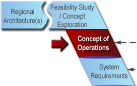
The Concept of Operations (ConOps) is a foundation document that frames the overall system and sets the technical course for the project. Its purpose is to clearly convey a high-level view of the system to be developed that each stakeholder can understand. A good ConOps answers who, what, where, when, why, and how questions about the project from the viewpoint of each stakeholder, as shown in Figure 12.
Figure 12: Concept of Operations (Adapted from ANSI/AIAA-G-043-1992)
In
ITS, we draw a distinction between an Operational Concept, which is the
high-level description of roles and responsibilities that is included in the
regional ITS architecture, and a Concept of Operations, which is the
more detailed, multifaceted document described in this section.
Don't
assume that a new ConOps is required for every ITS project. A single
system-level ConOps can support many ITS projects that incrementally implement
and extend a system. For example, a ConOps may be developed for a large
transportation management system. This system may be implemented and expanded
with numerous ITS projects over several years. Once the ConOps is developed,
it may be reviewed and used with relatively minor updates for each of the
projects that incrementally implement the transportation management system.
Although there is no single recipe for developing a ConOps, successful efforts will include a few key activities:
If
you hire a consultant, don't assume that is the end of your responsibility for
ConOps development. The stakeholders are the foremost experts on their needs
and must be materially involved in the ConOps development. The consultant can
provide technical expertise on what should be in a ConOps, facilitate the
meetings and outreach activities, prepare the document, and coordinate the
review, but the stakeholders' concept should be documented in the end. The
stakeholders should consider the ConOps their document, not the
consultant's document.
The
best person to write the ConOps may not be the foremost technical expert on the
proposed system. Stakeholder outreach, consensus building, and the ability to
understand and clearly document the larger picture are key.
Portions of the ConOps can often be created from existing documents. For example, the regional ITS architecture identifies stakeholder roles and responsibilities that can be used. A feasibility study, project study report, or other preliminary study documentation may provide even more relevant information. A project application form used to support project programming will normally include goals, objectives, and other information that should be reflected in the ConOps for continuity.
Operational
scenarios are an excellent way to work with the stakeholders to define a
ConOps. Scenarios associated with a major incident, a work zone, or another
project-specific situation provide a vivid context for a discussion of the
system's operation. It is common practice to define several scenarios that
cover normal system operation (the "sunny day" scenario) as well as various
fault-and-failure scenarios.
A System Validation Plan is prepared that defines the consensus validation approach and performance measures. As with the ConOps, all affected stakeholder organizations should formally approve the System Validation Plan at this early stage so that downstream, all will agree on when they can "declare victory" that the new system is the right system. The plan will be finalized during system validation (see Section 4.9.2).
The ConOps should be an approachable document that is relevant to all project stakeholders, including system operators, maintainers, developers, owners/decision makers, and other transportation professionals. The art of creating a good ConOps lies in using natural language and supporting graphics so that it is accessible to all while being technically precise enough to provide a traceable foundation for the requirements document and the System Validation Plan.
The
ConOps is not a requirements document that lists the detailed, testable
requirements for the system, nor is it a design document that specifies the
technical design or technologies to be used. Resist the temptation to
predetermine the solution in the ConOps – you should not unnecessarily preclude
viable options at this early step. You also want to "keep it simple" and
refrain from using formalized, highly structured English that is more suitable
for the requirements and design specifications that follow.
Done right, the ConOps will be a living document that can be revised and amended so that it continues to reflect how the system is really operated. Later in the life cycle, an up-to-date ConOps can be used to define changes and upgrades to the system.
Two different industry standards provide suggested outlines for Concepts of Operations: ANSI/AIAA-G-043-1992 and IEEE Std 1362-1998, as shown in Figure 13. Both outlines include similar content, although the structure of the IEEE outline lends itself more to incremental projects that are upgrading an existing system or capability. The ANSI/AIAA outline is focused on the system to be developed, so it may lend itself more to new system developments where there is no predecessor system. Successful ConOps have been developed using both outlines. Obtain a copy of both, and make your own choice if you need to develop a ConOps.
Figure 13: Industry-Standard Outlines for Concept of Operations
Graphics should be used to highlight key points in the ConOps. At a minimum, a system diagram that identifies the key elements and interfaces and clearly defines the scope of the project should be included. Tables and graphics can also be a very effective way to show key goals and objectives, operational scenarios, etc.
The
Rule/Policy requires identification of participating agency roles and
responsibilities as part of the systems engineering analysis for ITS projects.
It also requires that the procedures and resources necessary for operations and
management of the system be defined. These elements are initially defined and
documented for the project as part of the ConOps. In the ANSI/AIAA standard
outline, most of these elements fit under Chapter 3 (User-Oriented Operational
Description). In the IEEE outline, the current system information is included
in Chapter 3 and the proposed system information is in Chapter 5.
The System Validation Plan that is created during this step should describe how the final system will be measured to determine whether or not it meets the original intent of the stakeholders as described in the ConOps. (For further details and examples, see Section 4.9.)
Many Concepts of Operations have been generated for all types of ITS projects in the last five years. Excerpts from a few examples are included here to show some of the ways that key elements of the ConOps have been documented for ITS projects following the sequence from the ANSI/AAIA outline.
User-Oriented Operational Description (Roles and Responsibilities)
Typically, roles and responsibilities are documented as a list or in tabular form. Table 5 is an excerpt of a table from the California Advanced Transportation Management System (CATMS) ConOps that is structured to show shared responsibilities and to highlight coordination points between the different system stakeholders. This early documentation of "who does what" grabs the stakeholders' attention and supports development of system requirements and operational agreements and procedures in future steps.
Table 5: Roles and Responsibilities (Excerpt from CATMS Concept of Operations)
System Overview
The system overview is typically supported by one or more diagrams that show the scope, major elements, and interrelationships of the system. Many types of diagrams can be used, from simple block diagrams to executive-level graphics-rich diagrams. Figure 14 is an example of a high-level graphic that includes basic process flow information, roles and responsibilities, and interfaces, providing an "at a glance" overview of the major facets of the system.
Figure 14: Example of System Overview Graphic
(from Communicating with the Public Using ATIS During Disasters Concept of Operations)
Operational Scenarios
In operational scenarios, the ConOps takes the perspective of each of the stakeholders as different scenarios unfold that illustrate major system capabilities and stakeholder interactions under normal and stressed (e.g., failure mode) circumstances. The stakeholders walk through the scenario and document what the agencies and system would do at each step.
Figure 15 shows an example of a scenario that includes some realistic detail that help stakeholders immerse themselves in the scenario and visualize system operation. This is one of five scenarios that were developed for the City of Lincoln StarTRAN AVL system to show the major system capabilities and the interactions between the AVL system and its users and other interfacing systems.
Figure 15: Operational Scenario Description11
 In
this step: The stakeholder needs identified in the Concept
of Operations are reviewed, analyzed, and transformed into verifiable
requirements that define what the system will do but not how the
system will do it. Working closely with stakeholders, the requirements are
elicited, analyzed, validated, documented, and baselined.
In
this step: The stakeholder needs identified in the Concept
of Operations are reviewed, analyzed, and transformed into verifiable
requirements that define what the system will do but not how the
system will do it. Working closely with stakeholders, the requirements are
elicited, analyzed, validated, documented, and baselined.
| OBJECTIVES |
|
|---|---|
| INPUT
Sources of Information |
|
| PROCESS
Key Activities |
|
| OUTPUT
Process Results |
|
| Review
Proceed only if you have: |
|
One of the most important attributes of a successful project is a clear statement of requirements that meet the stakeholders' needs. Unfortunately, creating a clear statement of requirements is often much easier said than done. The initial list of stakeholder needs that are collected will normally be a jumble of requirements, wish lists, technology preferences, and other disconnected thoughts and ideas. A lot of analysis must be performed to develop a good set of requirements from this initial list.
Figure 16: Requirements Engineering Activities
EIA-63212
defines requirement as "something that governs what, how well, and under
what conditions a product will achieve a given purpose." This is a good
definition because it touches on the different types of requirements that must
be defined for a project. Functional requirements define "what" the system
must do, performance requirements define "how well" the system must perform its
functions, and a variety of other requirements define "under what conditions"
the system must operate. Requirements engineering covers all of the
activities needed to define and manage requirements that are shown in Figure 16.
Specify
What, Not How. Be sure to keep the definition of a requirement in mind as
you develop your system requirements. Many requirements documents contain
statements that are not requirements. One of the most common pitfalls is to
jump to a design solution and then write "requirements" that define how the
system will accomplish its functions. Specify what the system will do in the
system requirements, and save how the system will do it for the system design
step.
It is important to involve stakeholders in requirements development. Stakeholders may not have experience in writing requirements statements, but they are the foremost experts concerning their own requirements. The project requirements ultimately are the primary formal communication from the system stakeholders to the system developer. The project will be successful only if the requirements adequately represent stakeholders' needs and are written so they will be interpreted correctly by the developer.
In the
effort to get stakeholders involved, make sure you don't sour them on the
project by making unreasonable demands on their time or putting them in
situations where they can't contribute. Many nontechnical users have been
subjected to stacks of detailed technical outputs that they can't productively
review. Sooner or later, the user will wave the white flag in this situation
and become unresponsive. You must (1) pick your stakeholders carefully and (2)
make participation as focused and productive as possible.
The
Requirements step is an important one that you shouldn't skimp on. Every ITS
project should have a documented set of requirements that are approved and
baselined. Of course, this doesn't mean that a new requirements specification
must be written from scratch for every project. Projects that enhance or
extend an existing system should start with the existing system requirements.
This doesn't have to be a particularly large document for smaller ITS
projects. The system requirements specification for a recent website
development project was less than 20 pages.
There isn't one "right" approach for requirements development. Different organizations develop requirements in different ways. Even in the same organization, the requirements development process for a small ITS project can be much less formal than the process for the largest, most complex ITS projects. The differences are primarily in the details and in the level of formality. All requirements development processes should involve elicitation, analysis, documentation, validation, and management activities. Note that each of these activities is highly iterative. In the course of a day, a systems engineer may do a bit of each of the activities as a new requirement is identified, refined, and documented.
Elicit
and elicitation are words you may not run into every day. Elicit means
to draw forth or to evoke a response. This is the perfect word to use in this
case because you will have to do some work to draw out the requirements from
the stakeholders and any existing documentation. More work is implied by
"elicit requirements" than if we said "collect requirements" or even "identify
requirements", and this is intended.
Make
sure that you have the right stakeholders involved. This means not only the
right organizations but also the right individuals within them. For example,
it isn't enough to engage someone from the maintenance organization – it should
be an electrical maintenance person who has experience with ITS equipment
maintenance for ITS projects. Furthermore, as we move through the steps in the
process and the products become more technical, different stakeholders may be
involved. Managers may be more involved in the Concept of Operations, while
technical staff will be more involved in review of the system requirements and
high-level design. Finding individuals with the right combination of knowledge
of current operations, vision of the future system, and time to invest in
supporting requirements development is one of the key early challenges in any
requirements development effort.
There
are many techniques for working with stakeholders to get to the fundamental
requirements of the system. The Florida SEMP13
highlights one of the best and simplest techniques – the "Five Whys" – that was
popularized by Toyota in the 1970s. Using the Five Whys technique, you look at
an initially stated need and ask "Why?" repeatedly, not unlike a curious
four-year-old, until you find the real underlying requirements. The dialog in Table
6 is an example that is based on an actual conversation.
Table 6: The "Five Whys" Technique in Action
| Stakeholder | Systems Engineer |
|---|---|
| I need irrigation channels on my keyboard. | Why? |
| I occasionally spill coffee on the keyboard. | Why? |
| I need to have three or four manuals open to operate the system and the coffee just gets knocked over. | Why do you need to have three or four manuals open? |
| ... | ... |
| The dialog continues as the systems engineer discovers several different underlying needs that will drive environmental requirements, human factors/workspace requirements, and user interface requirements, all by pursuing the initial stated need for "irrigation channels". | |
Of course, you sometimes need to direct the conversation by asking more than "why" to use this technique effectively. In the example, the conversation could easily have veered off to a discussion of the user's love for Starbucks coffee. Five iterations is a good rule of thumb, but it may take fewer or more iterations – the idea is to be persistent until you get to the core issues. Note also that the dialog can be internal – the stakeholder could have sat down and asked herself "Why", using the same technique to get at her underlying needs.
As
you gather the requirements, be sure to look beyond the operational
requirements for the system and cover the complete life cycle (system
development, deployment, training, transition, operations and maintenance,
upgrades, and retirement) as well as requirements such as security and safety.
More than one ITS project has failed because the security requirements of
public safety stakeholders were not captured and reflected in the ITS project
requirements. A good system requirements template can be used as a checklist
to help ensure that all types of requirements are considered.
The
best way to start writing requirements is to use just two words: a verb and a
noun. For example, the user requirement "monitor road weather conditions"
would yield system requirements such as "shall detect ice", "shall monitor wind
speed", and "shall monitor pavement temperature". Performance requirements
would define the different kinds of ice conditions and the range of wind speeds
and pavement temperatures.
Requirements
are normally defined in a requirements hierarchy in which the highest-level
"parent" requirements are supported by more detailed "child" requirements. A
hierarchy allows you to start with high-level requirements and work your way
down to the details. The highest-level requirements should trace to
stakeholder needs in the Concept of Operations. A hierarchy is a useful
organizational structure that makes it easier to write and review requirements
and to manage the requirements development activity. An example of a
requirements hierarchy is given in Figure 17.
Figure 17: Example of Hierarchy of High-Level and Detailed Requirements
For larger systems, it can be
very difficult to "get your arms around" all of the requirements. Requirements
modeling tools provide a graphic way to define requirements so that they are
easier to understand and analyze. These tools are particularly useful for more
complex ITS projects. There are
numerous requirements modeling tools and techniques available that can help you
model the system as part of the analysis process. INCOSE maintains a data
repository of available modeling tools that is available on its website14.
A
model is a representation of something else. There are physical models,
like the scale model of a train, and more abstract models, like an
architectural plan for a new building. Many different models of the system to
be built can be created and used as part of the systems engineering process.
During requirements analysis, logical models are used that describe what the
system will do. Later, during system design, physical models are created that
show how the system will be implemented.
Requirements modeling is an iterative process. Draft models can be developed early in the process based on the Concept of Operations and the regional ITS architecture. These models are refined as they are used to support requirements elicitation and walkthroughs, keeping bounds on the system and reducing requirements creep.
The
requirements documentation should include more than requirements. There are
many different attributes that should be tracked for each requirement.
A rich set of attributes is particularly important for large, complex
projects. If you are developing such a project, consider specifying the following
for each requirement: requirement number, source, author, creation date,
change history, verification method, priority, and status. The historical and
change-tracking attributes are particularly important since they allow
management to measure and track requirements stability.
Traceability is another important aspect of requirements documentation. Each requirement should trace to a higher-level requirement, a stakeholder need, or other governing rules, standards, or constraints from which the requirement is derived. As the system is developed, each requirement will also be traced to the test case that will verify it, to more detailed "child" requirements that may be derived from it, and to design elements that will help to implement it. Establish and populate the Traceability Matrix at this stage, and continue to populate it during development. The Traceability Matrix is a vital document that is maintained to the end of project development, allowing traceability from user needs to the system components, verification, and validation.
You
will see "validation" used in a few different contexts in systems engineering.
Here in requirements validation, you make sure that the requirements are
correct and complete. Later, in system validation (discussed in Section
4.9), you make sure that you have built the right system. In fact, the
requirements validation that is performed here will ultimately help to make
sure that the system validation is successful in the end.
A
walkthrough is a technique in which a review team steps through a deliverable
(e.g., requirements, design, or code) looking for problems. A walkthrough
should be relatively informal and "blame free" to maximize the number of
problems that are identified. A requirements walkthrough should be attended by
the people that have a vested interest in the requirements. For a large
project, this might include the requirements author, customer, user
representative(s), implementers, and testers.
Table 7 identifies an oft-repeated list of attributes of good requirements. As part of the validation process, you do your best to make sure that the requirements have all of these desired attributes. Unfortunately, computers can do only a fraction of this validation and people have to do the rest. Techniques for validating a requirement against each of these quality attributes are also shown in Table 7. An attribute list like this can be converted into a checklist that prompts reviewers to ask themselves the right questions as they are reviewing the requirements.
Table 7: Validating Quality Attributes of Good Requirements
| Quality Attribute | Validate by: |
|---|---|
| Necessary | Make sure that each requirement traces to either a stakeholder need in the ConOps or a parent requirement. A computer can check that the traceability is complete, but people have to verify that the identified traces are valid. |
| Clear | Some requirements management tools can help with this by looking for red-flag words and constructs in the requirements (e.g., "user friendly", "optimum", "real-time", pronouns, and complex sentences). Most of this aspect of validation relies on walkthroughs and other reviews to make sure the requirements aren't subject to different interpretations. The main culprit here is ambiguity in the English language. |
| Complete | Does every stakeholder or organizational need in the ConOps trace to at least one requirement? If you implement all of the requirements that trace to the need, will the need be fully met? A computer can answer the first question, but only stakeholder(s) can answer the second. |
| Correct | In general, it takes a walkthrough to verify that the requirements accurately describe the functionality and performance that must be delivered. The stakeholders must validate that the highest-level system requirements are correct. Traceability can assist in determining the correctness of lower-level requirements. If a child requirement is in conflict with a parent requirement, then either the parent or the child requirement is incorrect. |
| Feasible | Again, this must be determined by review and analysis of the requirements. A computer can help with the analysis and possibly even flag words like "instant" or "instantaneous" that may be found in infeasible requirements, but a person ultimately makes the judgment of whether the requirements are feasible. In this case, it is the developer who can provide a reality check and identify requirements that may be technically infeasible or key cost drivers early in the process. Since system performance is dependent on system design and technology choices, requirements feasibility will continue to be monitored and addressed as the system design is developed. |
| Verifiable | Does the requirement have a verification method assigned? (This is something a computer can check.) Is the requirement really stated in a way that is verifiable? (This much more difficult check can only be performed by people.) For example, ambiguous requirements are not verifiable. |
Every
ITS project should have a tool that helps to manage the requirements baseline.
More complex ITS
projects will benefit from a tool specifically for requirements management such
as DOORS or Requisite-Pro.15
A professional requirements management tool is expensive, but it includes a
long list of capabilities including change management, requirements attributes
storage and reporting, impact analysis, requirements status tracking,
requirements validation tools, access control, and more.
Like the other requirements
engineering activities, the requirements management capabilities should be
scaled based on the complexity and size of the ITS project. Requirements for
smaller ITS projects can be managed easily and effectively by a single engineer
using a general purpose tool like Microsoft Access or Excel.
No matter how you developed your requirements, you must document them in some consistent, accessible, and reviewable way. The requirements development process may result in several different levels of requirements over several steps in the "V" – stakeholder requirements, system requirements, subsystem requirements, etc. – that may be documented in several different outputs. For example, stakeholder requirements might be documented in a series of Use Cases; system requirements, in a System Requirements Specification; and subsystem requirements, in subsystem specifications. All of these requirements should be compiled in a single repository that can be used to manage and publish the requirements specifications at each stage of the project.
It is much
easier to use a standard template for the requirements specifications than it
is to come up with your own, and numerous standard templates are available. If
your organization does not have a standard requirements template, you can start
with a standard template like the one contained in IEEE Standard 830 (for
software requirements specifications) or IEEE Standard 1233 (for system
requirements specifications). Starting with a template saves time and ensures
that the requirements specification is complete. Of course, the template can
be modified as necessary to meet the needs of the project.
The system requirements specification should fully specify the system to be developed and should include the following information:
As you read through this list, you may recognize that some of this information has already been collected and documented in previous steps, and there is no need to recreate it here. Refer back to the Concept of Operations that already contains a description of the system boundary, the system itself, and other items in this list.
A System Verification Plan, describing the approach for verifying each and every system requirement, and a System Acceptance Plan, describing the capabilities that must function successfully for customer acceptance, should be created, reviewed, and approved.
Stakeholder Requirements
The Oregon DOT TripCheck project developed a User Functional Requirements Specification, which lists the user requirements for the redesigned TripCheck website. The excerpt from this document in
Table 8 shows several user requirements for the website autorouting function. As shown, every requirement is prioritized on a scale from 1 ("must have") to 4 ("don't implement") and is related to different types of end users – Commuters (C), Inter-City Travelers (ICT), Tourist Travelers (TT), ADA Travelers (ADA), and Commercial Truckers (CT). These prioritized user requirements were used by the contractor to support Use Case modeling and to define system requirements.
Table 8: ODOT TripCheck User Requirements (Excerpt)
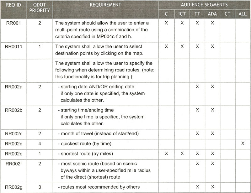
Note that stakeholder requirements that are collected through the requirements elicitation process are likely to have a few imperfections. The key is to document the stakeholder requirements, make them as clear and succinct as possible, prioritize them, and then use them to develop more formally stated system requirements.
System Requirements
The Maryland CHART II system is a statewide traffic management system that has been operational since 2001. The CHART program maintains a website that provides all of the CHART documentation at http://www.chart.state.md.us, including a comprehensive system requirements document. A few of the system requirements for the equipment inventory and report generation functions are shown in Table 9.
Table 9: CHART II System Requirements (Excerpt)
|
3.1.3 Equipment Inventory The equipment inventory is a list of SHA equipment used in connection with CHART response to incidents. The system provides functions to maintain the inventory, equipment status, and to generate alerts for delinquent equipment. |
|
3.1.3.1 The system shall provide the capability to maintain the equipment inventory. |
|
3.1.3.1.1 The system shall support the addition of new equipment entries to the inventory. |
|
3.1.3.1.2 The system shall support the modification of existing equipment inventory entries. |
|
3.1.3.1.3 The system shall support the deletion of equipment inventory entries. |
|
3.1.3.1.4 The system shall support the allocation of equipment to events. |
|
3.1.4 Report Generation This section lists requirements for the generation of reports from the CHART system and archive data. |
|
3.1.4.1 The system shall provide the capability to generate reports from online and archived data. |
|
3.1.4.2 The system shall support the generation of operational reports. |
|
3.1.4.2.1 The system shall support the generation of a Center Situation report. |
|
3.1.4.2.2 The system shall support the generation of a Disable Vehicle event report. |
|
3.1.4.2.3 The system shall support the generation of an Incident event report. |
|
3.1.4.2.4 The system shall support the generation of traffic volume reports. |
Traceability Matrix
Table 10 is a typical traceability matrix that would be maintained and populated throughout the project development process. The matrix may be maintained directly in a database or spreadsheet for small projects or generated and maintained with a requirements management tool for more complex projects. Using either approach, the matrix provides backwards and forwards traceability between stakeholder needs (and other potential requirements sources), system requirements, design, implementation, and verification test cases. As shown, only the unique identifiers (e.g., UN1.1) are actually included in the traceability matrix so you don't have to keep many instances of the actual text up-to-date. Note also that the design and implementation columns would not actually be completed until later in the process.
Table 10: Sample Traceability Matrix
| Requirement Source | System Requirement | High-Level Design Component | Code Unit | Test Case |
|---|---|---|---|---|
| UN1.1 | R00220 | 7.2.3 | SystemMonitor | UT 4.2 |
| R00330 | 7.3.1 | CalcVolume | UT 5.5 | |
| R00331 | 7.3.1 | CalcCount |
 In this step: A system design is created
based on the system requirements including a high-level design that defines the
overall framework for the system. Subsystems of the system are identified and
decomposed further into components. Requirements are allocated to the system
components, and interfaces are specified in detail. Detailed specifications
are created for the hardware and software components to be developed, and final
product selections are made for off-the-shelf components.
In this step: A system design is created
based on the system requirements including a high-level design that defines the
overall framework for the system. Subsystems of the system are identified and
decomposed further into components. Requirements are allocated to the system
components, and interfaces are specified in detail. Detailed specifications
are created for the hardware and software components to be developed, and final
product selections are made for off-the-shelf components.
| OBJECTIVES |
|
|---|---|
| INPUT
Sources of Information |
|
| PROCESS
Key Activities |
|
| OUTPUT
Process Results |
|
| Review
Proceed only if you have: |
|
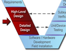
In the systems engineering approach, we define the problem before we define the solution. The previous steps in the "V" have all focused primarily on defining the problem to be solved. The system design step is the first step where we focus on the solution. This is an important transitional step that links the system requirements that were defined in the previous step with system implementation that will be performed in the next step, as shown in Figure 18.
Figure 18: System Design is the Bridge from Requirements to Implementation
There are two levels of design that should be included in your project design activities:
High-level
design is commonly referred to as architectural design in most
systems engineering handbooks and process standards. Architectural design is
used because an overall structure for the project is defined in this step.
IEEE 61016
defines architectural design as "the process of defining a collection of
hardware and software components and their interfaces to establish the
framework for the development of a computer system". Of course, ITS
projects may include several computer systems, a communications network,
distributed devices, facilities, and people. High-level design defines a
framework for all of these project components.
Detailed
design is the complete specification of the software, hardware, and
communications components, defining how the components will be developed
to meet the system requirements. The software specifications are described in
enough detail that the software team can write the individual software
modules. The hardware specifications are detailed enough that the hardware
components can be fabricated or purchased.
Many consider design to be the most creative part of project development. Two different designs might both meet the system requirements, but one could be far superior in how efficiently it can be developed, integrated, maintained, and upgraded over time. Perhaps the most significant contributor to a successful design is previous design experience with similar systems. The latest car designs all build on 100 years of accumulated automotive design experience. Similarly, the design of a new transportation management system should build on existing successful transportation management system designs. In both cases, the system designer builds on knowledge of what worked before and, perhaps even more importantly, what did not.
It is
extremely rare to find an ITS system that is truly "unprecedented", so many if
not most system designs should be able to build on existing design
information. This is particularly true for projects that are extending an
existing system that already includes a well- documented design. In this
case, the high-level design will change only to the degree that new
functionality or interfaces are added. Similarly, much of the detailed design
can be reused for projects that extend the coverage of an existing system.
System design is a cooperative effort that is performed by systems engineers and the implementation experts who will actually build the system. The process works best when there is a close working relationship among the customer, the systems engineers (e.g., a consultant or in-house systems engineering staff), and the implementation team (e.g., a contractor or in-house team).
High-Level Design
High-level design is normally led by systems engineers with participation from the implementation experts to ensure that the design is implementable. Typical activities of high-level design are shown in Figure 19. Each of the activities are actually performed iteratively as high-level design alternatives are defined and evaluated.
Figure 19: High-Level Design Activities
When off-the-shelf components will be used, the high-level design must be consistent with the capabilities of the target products. The designer should have an eye on the available products as the high-level design is produced to avoid specifying a design that can be supported only by a custom solution. A particular product should not be specified in the high-level design unless it is truly required. When possible, the high-level design should be vendor and technology independent so that new products and technologies can be inserted over time.
You
should give off-the-shelf hardware and software serious consideration and use
it where it makes sense. The potential benefits of off-the-shelf solutions –
reduced acquisition time and cost, and increased reliability – should be
weighed against the requirements that may not be satisfied by the off-the-shelf
solution and potential loss of flexibility. If you have requirements that
preclude off-the-shelf solutions, determine how important they are and what
their real cost will be. This make/buy evaluation should be documented in a
summary report that considers the costs and benefits of off-the-shelf and
custom solution alternatives over the system life cycle. This report should be
a key deliverable of the project.
Also recognize that there is a large grey area between off-the-shelf and custom software for ITS applications. Every qualified software developer starts with an established code base when creating the next "custom solution", accruing some of the benefits of off-the-shelf solutions. Many vendors of off-the-shelf solutions offer customization services, further blurring the distinction between off-the-shelf and custom software.
The
FHWA report The Road to Successful ITS Software Acquisition includes a
good discussion of software make/buy decision factors and a lot of other good
information on software acquisition for ITS. The executive summary for the
report is available at www.itsdocs.fhwa.dot.gov/jpodocs/repts_te/36s01!.pdf.
Figure 20: Electronic Toll Collection Subsystems and Components (Excerpt)
There are many different ways that a system can be partitioned into subsystems and components. In this Electronic Toll Collection example, we might consider whether the Clearinghouse Processing subsystem should be handled by a single centralized facility or distributed to several regional facilities. As another example, vehicle detectors could be included in the Video Enforcement subsystem or in the Tag Reader subsystem, or both.
Even a relatively simple traffic signal system has high-level design choices. For example, a traffic signal system high-level design can be two-level (central computer and local controllers), three-level (central computer, field masters, and local controllers), or a hybrid design that could support either two or three levels. High-level design alternatives like these can have a significant impact on the performance, reliability, and life-cycle costs of the system. Alternative high-level designs should be developed and compared with respect to defined selection criteria to identify the superior design.
The selection criteria that are used to compare the high-level design alternatives include consistency with existing physical and institutional boundaries; ease of development, integration, and upgrading; and management visibility and oversight requirements. One of the most important factors is to keep the interfaces as simple, standard, and foolproof as possible. The selection criteria should be documented along with the analysis that identifies the superior high-level design alternative that will be used. If there are several viable alternatives, they should be reviewed by the project sponsor and other stakeholders.
The
Rule/Policy requires the systems engineering analysis for ITS projects to
include an analysis of alternative system configurations.
The detailed functional requirements and associated performance requirements are allocated to the system components. To support allocation, the relationships between the required system functions are analyzed in detail. Once you understand the relationships between functions, you can make sure that functions that have a lot of complex and/or time-constrained interactions are allocated to the same component as much as possible. Through this process, each component is made as independent of the other components as possible.
You
would not want to develop a high-level design and requirements allocation for a
complex ITS project without software tools. Fortunately, there are many good
tools that support both requirements analysis and architectural design. The
INCOSE tools database, available to nonmembers free of charge at www.incose.org, includes a broad range of
systems engineering tools and a detailed survey of tools that support
requirements management and system architecture.
This is the place to identify ITS standards and any other industry standards that will be used in detail. There are a variety of standards that should be considered at this point. Take a look at all interfaces, both external and internal. Since your regional ITS architecture and/or project ITS architecture was based on the National ITS Architecture, many of the interfaces probably already have a set of ITS standards you should consider. You should also identify standards that are used in your region or state, and also in adjoining states if your project is a multistate deployment. A methodical assessment should be made for each interface to determine which standards are relevant, which standards should be deployed, and perhaps which standards should be phased in over time as part of a longer-range plan.
Once you have taken a look at the relevant standards, beginning with your system's external interfaces, document the nature of the data, formats, ranges of values, and periodicity of the information exchanged on the interface. Then proceed to each of the internal interfaces and document the same information for those.
Agencies are encouraged to
incorporate the ITS standards into new systems and upgrades of existing
systems. The
Rule/Policy requires the systems engineering analysis for ITS projects to
include an identification of ITS standards. Consult the ITS Standards Program
website at http://www.standards.its.dot.gov/
for more information and available resources supporting standards
implementation.
Detailed Design
Hardware and software specialists create the detailed design for each component identified in the high-level design. Systems engineers play a supporting role, providing technical oversight on an ongoing basis. As you might expect, the detailed design activity will vary for off-the-shelf and custom components, as shown in Figure 21.
Figure 21: Detailed Design Activities
A
prototype is a quick, easy-to-build approxi-mation of a system or part of a
system. A software prototype can be used to quickly implement almost any part
of a system that you want to explore, but it is used most often to make a quick
approximation of a user interface for a new system.
A
user interface prototype should be employed to help the user and developer
visualize the interface before significant resources are invested in software
development. This is one area in particular where you can expect multiple
iterations as the developers incrementally create and refine the user interface
design based on user feedback. (You will find that it is often easier to get
users to provide feedback on a prototype than on system requirements and design
specifications, which can be tedious to review.)
While the user interface prototype is included here because it is an effective way to design the user interface, prototypes may actually be generated much earlier in the process, during system requirements development. The prototype can turn the requirements statements into something tangible that users can react to and comment on.
Figure 22: Architectural Design within a System Component
The detailed design of each component should be reviewed to verify that it meets the allocated requirements and is fit for the intended purpose. Periodic or as-needed reviews can be held to monitor progress and resolve any design issues. For larger projects, coordination meetings should be held to ensure that concurrent design activities are coordinated to mitigate future integration risks. At the completion of the detailed design step, a broader stakeholder meeting is held to review and approve the detailed design before the implementation team begins to build the solution.
There are two fundamental ways that a product can be selected, depending on your procurement requirements and selected procurement strategy:
In either case, product selection should be driven by a good performance-based specification of the product.
Specifications
can be either performance-based or prescriptive. In a
performance-based specification, you specify the functionality and the
performance that are required rather than what equipment to use. In a
prescriptive specification, you specify exactly the equipment that you want. A
performance-based specification for a dynamic message sign would include
statements like "The sign shall provide a display of 3 lines of 25 characters
per line." A prescriptive specification would be "The Trantastic LED Model XYZ
sign shall be used." Performance-based specifications tend to provide the best
value because they allow the contractor or vendor maximum flexibility to
propose the best solution that meets your needs.
If a trade study is performed, then the functional and performance requirements that are allocated to the product should be used to define product selection criteria. An alternatives analysis document captures the alternatives that were considered and the selection criteria that were used to select the superior product. Existing trade studies, approved product lists, and other resources can be used to facilitate product selection.
The evaluation of OTS products should be reviewed to verify that the evaluation criteria were properly defined and applied fairly and that an appropriate range of products was considered.
High-Level Design
There isn't a single "best way" to present the high-level design to stakeholders and developers since different users will have different needs and different viewpoints. Over the years, high-level designs have evolved to include several different interconnected "views" of the system. Each view focuses on a single aspect of the system, which makes the system easier to analyze and understand. The specific views that are presented will vary, but they will typically include a physical view that identifies the system components and their relationships; a functional view that describes the system's behavior; a technical view that identifies the interfaces in detail, including the standards to be used; and an informational view that describes the information that will be managed by the system. As shown in Figure 23, these views are just different ways of looking at the same system.
Figure 23: High-Level Design May Include Several Views
Other outputs of the high-level design process include Integration Plans, Subsystem Verification Plans, and Subsystem Acceptance Plans that will be used in the integration and verification of the system. (See Section 4.7 for further details.)
Detailed Design
This activity results in the design of hardware and software for all system components that will support hardware and software development and off-the-shelf product procurement. Other artifacts of the development process include unit/device verification plans. A record of the technical reviews that were conducted should also be included in the project documentation.
High-Level Design
The CHART II documentation includes a system architecture document that includes many different views of the CHART II system, such as entity relationship diagrams, Use Case diagrams, and network architecture diagrams. Table 11 is an excerpt from the document that shows the subsystems included in the CHART II software.
Table 11: CHART II Software Subsystems (Excerpt)
| Software | |
|---|---|
| CI Name | Subsystems |
| CHART II |
Alert Management
Audio
AVL
Camera Control
Communications Log Management
Data Export Management
Device Management
Dictionary
DMS Control
HAR Control
HAR Notification
Message Library Management
Notification Management
Plan Management
Resource Management
Schedule Management
SHAZAM Management
Signals
Simulation
System Monitor
Traffic Event Management
Traffic Sensor System Management
User Management
Utility
Video Monitor Management
|
In contrast with the CHART II statewide system high-level design, many smaller ITS projects have relatively simple high-level designs, such as the system architecture for the MyBus system depicted in Figure 24. This figure identifies the subsystems and major interfaces in the MyBus system.
Figure 24: Metro Transit MyBus System Architecture
ITS projects that include significant user interface development should prototype the user interface to help users visualize the software that will be developed before significant resources are committed. The objective is to develop a prototype that demonstrates the software look and feel with the least amount of work possible. The simplest prototypes are a series of static images in paper form. For example, when ODOT redesigned its TripCheck website, the implementation team developed a series of "wireframe" diagrams that showed the proposed interface design with enough detail to gather user feedback. One of the 40 wireframe diagrams that was included in the design package is shown in Figure 25.
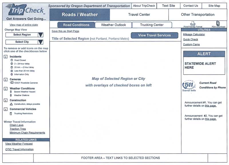
Figure 25: User Interface Prototype Example: ODOT TripCheck Wireframe Diagram
Detailed Design
There are many ways to document software detailed design. Most commonly, it is portrayed using object-oriented techniques and the Unified Modeling Language17, but any technique that the implementation team selects is fine as long as it is detailed enough to support software construction and clear enough to support peer reviews and walkthroughs.
Table 12 is an example of a detailed design for part of the Shadow software that works behind the scenes to keep the traffic information on the ODOT TripCheck website up to date. Note that the interface is defined and that loosely structured program design language (PDL) is used to define the algorithm that is used to process transactions. If much of this appears to be gibberish to you, you are not alone. This is why many agencies use software specialists to provide an independent review of the detailed software development artifacts for higher risk software projects on their behalf.
Table 12: Detailed Software Design Example: ODOT TripCheck Software Class Definition
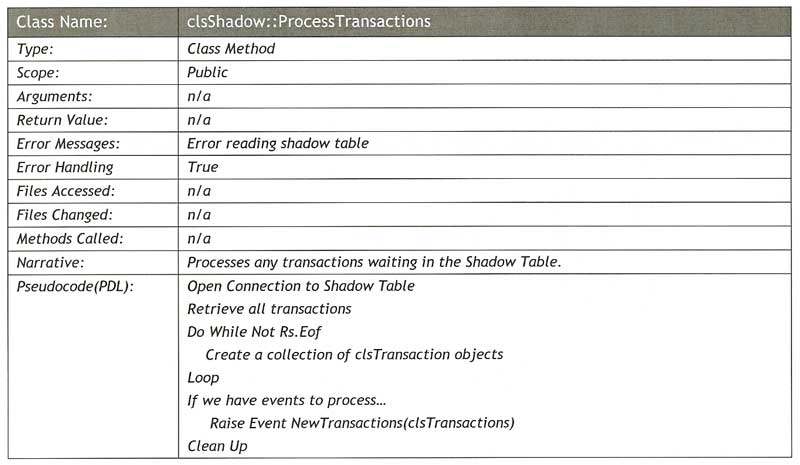
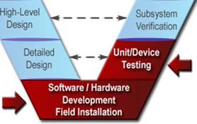 In
this step: Hardware and software solutions are created for
the components identified in the system design. Part of the solution may
require custom hardware and/or software development, and part may be
implemented with off-the-shelf items, modified as needed to meet the design
specifications. The components are tested and delivered ready for integration
and installation.
In
this step: Hardware and software solutions are created for
the components identified in the system design. Part of the solution may
require custom hardware and/or software development, and part may be
implemented with off-the-shelf items, modified as needed to meet the design
specifications. The components are tested and delivered ready for integration
and installation.
| OBJECTIVES |
|
|---|---|
| INPUT
Sources of Information |
|
| PROCESS
Key Activities |
|
| OUTPUT
Process Results |
|
| Review
Proceed only if you have: |
|
Although hardware and software development may be the first task that comes to mind when thinking about an ITS project, the systems engineering approach focuses on the preceding requirements and design steps and on the integration, verification, and validation steps to follow.
This is where the investment in a clear set of requirements and a good system design should begin to pay dividends. The systems engineering process now provides technical oversight as an implementation team of specialists fabricates the hardware and writes the software. This is a highly iterative process, particularly for software, where key features may be incrementally implemented, tested, and incorporated into the baseline over time. Progress is monitored through a planned series of walkthroughs, inspections, and reviews, as shown in Figure 26.
Figure 26: Monitoring Software/Hardware Development
Although the systems engineering approach does not specify the mechanics of hardware and software development (this is left to the implementation team), the development effort is obviously critical to project success. This is the time to build quality into the hardware/software and to minimize defects. A common refrain in the software industry is that you can't test quality into the software – you must build it in from the beginning. The systems engineering activities that are suggested in this chapter are intended to ensure that the implementation team builds quality into their products.
In
practice, most of the hardware that is used for ITS projects is purchased off
the shelf. Software development is more prevalent, but many ITS projects
include little or no software development. ITS projects that do not include
custom hardware or software development acquire the necessary off-the-shelf
hardware and software components at this step. Detailed specifications created as part of the detailed
design step described in Section 4.5 are used to support the acquisition.
The system components are acquired, and bench testing is performed to verify
that they meet their specifications. In such cases, the detailed
hardware/software development and unit testing described in this chapter are
not required.
Custom software development for ITS projects has proven to be a relatively risky endeavor. This is why software development receives more attention than hardware development in this chapter. It is beyond the scope of this document to discuss specific software development techniques, but there are several clear factors that contribute to software development success:
No matter how clear
and unambiguous the requirements appear, it is almost certain that the software
customer and the software implementation team will interpret some of the
requirements differently. Requirements walkthroughs that are described in
Section 4.4.2 help to mitigate this risk, but ultimately the
customer/stakeholders will have to monitor the software as it is being
developed to ensure that the development is proceeding in the right direction.
Expect and plan for course corrections and requirements changes along the way,
at least until we discover the way to build the "perfect specification".
Ensure that the contract is flexible enough to have a couple of reviews and
that it allows some visits or informal reviews with the developers to see how
they are doing. This might be one of the project risks to include in your risk
management plan. (See Section 5.3 for more information on risk management.)
All documentation
should be reviewed and approved. One of the biggest problems faced by system
implementers is the customer's failure to review documentation, which leads to
a system at the end of the project that does not meet the customer's
expectations. If the documentation that is generated is not reviewed, then
much of the benefit of systems engineering will not be realized. Depending on your background, you
may need to find experts who can review more technical documentation on your
behalf.Perhaps the best way to
reduce software development risk is to proceed in small steps and build
incremental software releases in short, successive time periods. Unlike a
typical roadway project that can be fully specified and implemented all at
once, complex software should be implemented incrementally, with months or even
weeks between releases. Incremental, iterative development with frequent
coordination and feedback is the best way to keep software development on
track, particularly for projects where the requirements are not completely
understood at the outset.The hardware and software specialists implement and test each system component. Systems engineers play a supporting role, providing technical oversight on an ongoing basis to identify minor issues early, before they grow into large problems. The process works best when there is a close working relationship among the customer, the systems engineers (e.g., a consultant or in-house systems engineering staff), and the implementation team (e.g., a contractor or an in-house team). Each of the activity descriptions is followed by a discussion of the technical review and monitoring of that activity.
The
Software/Hardware Development plan should be reviewed and approved before development
begins. Well-qualified implementation teams will already have proven processes
in place that can be tailored for the specific project, so this shouldn't be
viewed as a burdensome activity. The intent is not to mandate a particular
implementation process but to ensure that the implementation team has an
established process that they will follow. An implementation team that doesn't
have a documented process is a red flag.
Although
it is sometimes overlooked, the development environment is just as critical to
future software maintenance as the actual detailed design documentation and
source code. Every tool that is used to develop and test the software should
be documented, including version information and complete documentation of any
customization or extensions. If this is a custom development and you have paid
for the tools, include the development environment as a project deliverable.
A peer review or inspection can be used to verify that the development environment is adequate and accurately documented. Once established, the development environment should be placed under configuration management (discussed in Section 5.4) so that changes to the environment are tracked. Seemingly minor changes like application library upgrades or operating system service pack upgrades can cause problems later if they are not controlled and tracked.
Delay
procurement until the products are actually required to support the
implementation. Too much lead time can result in hardware or software that
becomes outdated before it can be integrated into the project. Too little lead
time could cause procurement delays that impact the project schedule.
Releases will be developed, tested, and made available to selected users for feedback. Providing feedback on interim releases is only part of the technical oversight that should be performed. Code inspections and code walkthroughs should also be used to check the software quality; these are the only ways to ensure that the software is well structured, well documented, and consistently follows the coding standards and conventions. Independent reviewers with software expertise should be used to help verify software quality on the customer's behalf if the customer agency does not have the right expertise.
Most
project managers who have managed software development efforts are familiar
with the "90% complete" syndrome, in which software developers quickly reach
"90% complete" status but the development effort then languishes as the final 10%
takes much more work than anticipated. Project tracking should be based on
discrete, measurable milestones instead of arbitrary "% complete" estimates
from the software developers. For example, instead of tracking the developer's
estimated "% complete", set up a monitoring system that gives credit for
completed software only when the piece of code has been successfully tested and
integrated into the next release.
Like the end-product hardware and software components, the supporting products can also be developed in stages and released incrementally to encourage early customer feedback.
While
the developers will conduct their own tests to identify and fix as many defects
as possible, experience shows that the test cases and formal tests should be
conducted by an independent party, either within the implementation team or
from another organization. The reason for this independence is obvious if you
look at the objectives of the software developer and the software tester. The
primary objective for the tester is to break the software while the primary
objective of the developer is the exact opposite – to make the software work.
Few individuals can effectively wear both of these hats. The degree of
independence between the developer and the tester (i.e., different people in
the same department, different departments, or different companies) and the
level of formality in unit testing should be commensurate with the criticality
of the software and the size of the project.
The unit verification plan should be reviewed to confirm that it will thoroughly test the hardware/software unit. The traceability matrix should be updated to identify the components, test cases, and test status. The testing should be tracked as it progresses to verify that defects are being identified and addressed properly. A testing process that identifies few defects could indicate excellent software or an incomplete or faulty testing process. Use scheduled technical reviews to understand the real project status. You can monitor the rate at which defects are being discovered to estimate the number of remaining defects and make an educated decision about when the hardware/software will be ready for release.
This step results in hardware and software components that are tested and ready for integration and verification. Artifacts of the development process are also delivered, including the Software/Hardware Development Plans, development environment documentation, unit test results, change control records, and supporting products and documentation. A record of the technical reviews that were conducted should also be included in the project documentation.
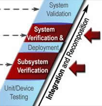 In this step:
The software and hardware components are individually verified and then
integrated to produce higher-level assemblies or subsystems. These assemblies
are also individually verified before being integrated with others to produce
yet larger assemblies, until the complete system has been integrated and
verified.
In this step:
The software and hardware components are individually verified and then
integrated to produce higher-level assemblies or subsystems. These assemblies
are also individually verified before being integrated with others to produce
yet larger assemblies, until the complete system has been integrated and
verified.
| OBJECTIVES |
|
|---|---|
| INPUT
Sources of Information |
|
| PROCESS
Key Activities |
|
| OUTPUT
Process Results |
|
| Review
Proceed only if you have: |
|
In this step, we assemble the system components into a working system and verify that it fulfills all of its requirements. Assembling a puzzle is a nice, simple analogy for this step, but the challenge in an ITS project "puzzle" is that you may find that not all of the pieces are available at the same time, some won't fit together particularly well at first, and there will be pressure to change some of the pieces after you have already assembled them. The systems engineering approach provides a systematic process for integration and verification that addresses the challenges and complexity of assembling an ITS system.
Integration and verification are iterative processes in which the software and hardware components that make up the system are progressively combined into subsystems and verified against the requirements, as shown in Figure 27. This process continues until the entire system is integrated and verified against all of its requirements. This is the opposite of the decomposition that was performed during the Requirements and Design steps, which is reflected in the symmetry between the left and right sides of the "V". Components that are identified and defined on the left side of the "V" are integrated and verified on the right.
Figure 27: Iterative Integration and Verification
In systems engineering, we draw a
distinction between verification and validation. Verification confirms
that a product meets its specified requirements. Validation confirms
that the product fulfills its intended use. In other words, verification
ensures that you "built the product right", whereas validation ensures that you
"built the right product". This is an important distinction because there are
lots of examples of well-engineered products that met all of their requirements
but ultimately failed to serve their intended purpose. For example, a bus
rapid transit system might implement a signal priority capability that
satisfies all of its requirements. This system might not serve its intended
purpose if the traffic network is chronically congested and the buses are never
actually granted priority by the signal control system when they need it most.
Verification is discussed in this section; system validation is described in
Section 4.9.
Integrating and verifying the system are key systems engineering activities. The software and hardware specialists who led the previous step are also involved and provide technical support as their components are integrated into the broader system. Stakeholders should also be materially involved in verification, particularly in the system verification activities. As the verification proceeds from detailed component verification to end-to-end system verification, the implementation team becomes less involved and the stakeholders become more involved. The systems engineering activity provides continuity to the process.
Integrating and verifying the system include basic planning, preparation, and execution steps, described as follows:
The integration plan defines the order in which the project components are integrated with each other and with other systems. Each integration step includes tests that verify the functionality of the integrated assembly, with particular focus on the interfaces. For less complex projects, the integration plan can be informal. For complex projects, there will have to be careful planning so that the system is integrated in efficient, useful increments consistent with the master schedule.
The verification plan is expanded into procedures that define the step-by-step process that will be used to verify each component, subsystem, and system against its requirements. For efficiency, test cases are identified that can be used to verify multiple requirements. Each test case includes a series of steps that will be performed, the expected outputs, and the requirements that will be verified by each step in the test case.
The
systems engineering analysis requirements identified in FHWA Rule 940.11/FTA
Policy Section VI include "identification of ... testing procedures", which are
the same as the verification procedures that are described here.
Every
round of verification that is performed as the system is integrated should be
thorough so that defects are identified as early and at as low a level as
possible. It is much easier to isolate a defect during component-level
verification than it is during system verification, when the entire system is
assembled and many different components could be contributing to the problem.
To put it in plain language, it is much easier to find the needle before you
have assembled a haystack around it.
If
test and simulation tools are used to support system verification, then these
tools should first be verified with the same care as the system. Verifying a
system using a simulator that has not been verified could result in invalid
results or compensating errors in which a defect in the end product is masked
by a defect in the verification tool.
There are four basic techniques that are used to verify each requirement:
Demonstration:
Witnessing system operation in the expected or simulated environment
without need for measurement data. For example, a requirement that an alarm is
issued under certain conditions could be verified through demonstration.
Demonstrations are more prevalent in system-level verification when the complete
system is available to demonstrate end-to-end operational capabilities.As each test case is performed, all actions and system responses are recorded. Unexpected responses are documented and analyzed to determine the cause and to define a plan of action, which might involve repeating the test, revising the test case, fixing the system, or even changing the requirement. Any changes to the test cases, the requirements, or the system are managed through the configuration management process.
It
is important to keep strict configuration control over the system components
and documentation as you proceed through verification. The configuration of
each component and the test-case version should be verified and duly noted as
part of the verification results. It is human nature to want to find and fix a
problem "on the spot", but it is very easy to lose configuration control when
you jump in to make a quick fix. (See Section 5.4 for more information about
configuration management.)
As
verification proceeds, you normally will have to retest each portion of the
system more than once. For example, a new software release that adds new
capabilities or fixes previously identified defects may be produced. It is
important not only to verify the new features or bug fixes when verifying the
new release but also to do regression testing to verify that the portion
of the software that used to work still does. Regression tests are important
because experience shows that old defects may reappear in later releases or
that a fix to one part of the software may break another part. For large
projects, automated testing tools can be used to automatically run a suite of
regression tests to fully test each new software release.
Resist the temptation to scale
back verification activities due to budget or schedule constraints. This would
be false economizing because defects that slip through will be even more
expensive to fix later in the system life cycle. As
previously noted, it is most efficient to identify defects early in the
verification process. This approach also minimizes the number of issues that
will be identified during system verification, which is the most formal and
most scrutinized verification step. Issues that occur during a formal system
verification that is witnessed by stakeholders can undermine confidence in the
system. Be sure to run the system verification test cases beforehand to the
extent possible to reduce the risk of unexpected issues during formal system
verification.
Integration and verification result in a documentation trail showing the activities that were performed and their results. The outputs include:
Many verification plans that have been developed for ITS projects are available on the Internet. Although they have many different titles – integration test plans, functional test plans, verification plans – they have similar content. For example, Table 13 is an excerpt from a functional test plan that was used to test the Oregon DOT TripCheck website. The script in the table lists each action that the tester should take and the expected result from the system in a step-by-step procedure that tests links in a website navigation panel.
Table 13: Verification Procedure Example: ODOT TripCheck Functional Test Plan (Excerpt)
| STEP | INPUT | SCRIPT | EXPECTED RESULT |
|---|---|---|---|
| 1 | None | Test winter travel links | |
| 1.a | Select Chain Laws | Opens: Pages/RCMap.asp?curRegion=ChainLaws | |
| 1.b | Select Traction Tires | Opens: Pages/RCMap.asp?curRegion=TractionTires | |
| 1.c | Select Minimum Chain Requirements | Opens: Pages/RCMap.asp?curRegion=MinChainReqs | |
| 2 | None | Test related links | Each link opens a browser window with an external URL |
Table 14 is a verification procedure from a Maryland Chart II Integration Test Plan that includes a bit more background for each test case in a slightly different format.
Table 14: CHART II Integration Test Plan (Excerpt)
| Test ID: General 1 | ||||
| Purpose: To show that a valid username/password is accepted for logging in to CHART II within 15 seconds, and that an invalid combination is rejected. In addition, this test case also demonstrates that the system returns control to the user and the user is not prevented from performing activities in other windows on the desktop. CHART-27, CHART-10, CHART-21, CHART-275, CHART-276, CHART-29, CHART-26 | Test Start Date: | |||
| Test Pre-Conditions: This test assumes a valid username and password of a user in the CHART2 system is known. | Test End Date: | |||
| Test Step No. | Test Steps | Expected Behavior | Results As Expected (Y/N) | Comments |
| 1 | Click on the Login button on the GUI toolbar. | An hourglass should display immediately, within 5 seconds, till the login window is displayed. Then, you should be prompted for a UserID and password. | ||
| 2 | Attempt to login with an invalid username or password. | The system should popup an error message indicating that an invalid user ID or password was specified. | ||
| 3 | Attempt to login with the valid UserID and password. | The system should indicate that the user is logged in by showing Operations Center:Username on the GUI toolbar window. | ||
| 4 | Click on Navigator | Navigator window is opened. | ||
| 5 | Click on DMS node | List of DMSs is displayed on the right hand side of the Navigator. | ||
Reports are generated that document the actual results of the verification tests that were performed. Table 15 is a brief excerpt from a test result report for the desktop application that is used by ODOT to update data on the TripCheck website. Each row in the table summarizes the results for each test case. This excerpt was selected because it includes one of the few test cases in this report in which the actual results did not match the expected results. Note that in Test 2, an error occurred that exposed a software defect that had to be fixed. Identification of defects like this before the system is operational is one of the key benefits of a thorough verification process.
Table 15: ODOT TripCheck 2.0 System Test Results (Excerpt)
| DESCRIPTION OF TEST | INPUT DATA | EXPECTED RESULTS | ACTUAL RESULTS |
|---|---|---|---|
| 1 Enter an incident of type Herbicide Application. | An incident of type Herbicide Application. | Does not appear in TripCheck. | As expected, incident did not go into the transaction table. |
| 2 Enter an incident that is then put on hold. | An incident that is on hold. | Does not appear in TripCheck. | When incident is put on hold a delete transaction is entered in the shadow table. An error occurred with this delete transaction and the incident remained on TripCheck. |
| 3 Put the incident from step 2 back into active status in HTCRS. | Incident is on TripCheck. | As expected. |
 In
this step: The system is installed in the operational
environment and transferred from the project development team to the
organization that will own and operate it. The transfer also includes support
equipment, documentation, operator training, and other enabling products that
support ongoing system operation and maintenance. Acceptance tests are
conducted to confirm that the system performs as intended in the operational
environment. A transition period and warranty ease the transition to full
system operation.
In
this step: The system is installed in the operational
environment and transferred from the project development team to the
organization that will own and operate it. The transfer also includes support
equipment, documentation, operator training, and other enabling products that
support ongoing system operation and maintenance. Acceptance tests are
conducted to confirm that the system performs as intended in the operational
environment. A transition period and warranty ease the transition to full
system operation.
| OBJECTIVES |
|
|---|---|
| INPUT
Sources of Information |
|
| PROCESS
Key Activities |
|
| OUTPUT
Process Results |
|
| Review
Proceed only if you have: |
|
Up to this point, the system has been tested primarily in a lab environment. The next step is to ship the system to the actual deployment site(s), install and check it out, and make sure the system and personnel are ready to transition to system operations and maintenance (O&M), as shown in Figure 28.
Figure 28: Transition from Development Team to Operations and Maintenance Team
Larger systems may be installed in stages. For example, a closed-circuit television (CCTV) camera network may be built out incrementally over the course of several years and several projects. This may be done to spread the costs across several fiscal years or to synchronize with other construction projects in the region. In other cases, phased deployment may be performed to mitigate risk by deploying the essential core of the system and then adding features over time. If it is necessary to deploy the system in stages, whether due to funding constraints, to mitigate risk, or to synchronize with other projects, it is important to understand the dependencies between successive deployments and to prioritize the projects accordingly.
The following tasks are cooperatively performed to deliver, install, and transition the system to full operational status:
The
deployment strategy should take into consideration the complexity of the
system, whether it will be deployed at multiple sites, and, if so, the order of
the deployments. It might be a good idea to bring up a minimal configuration
or a single installation at first and to add further functionality and other
sites once the initial installation is operational.
Until delivery, the system's components – the hardware and software – have been inventoried and under version control by the engineering team. Once delivered, however, ownership may change hands to the agency that will operate and maintain the system. The engineering and operating agencies should come to agreement ahead of time regarding who will maintain the inventory, the version of the software and hardware, any vendor maintenance agreements, and maintenance records to facilitate system delivery.
When the system is delivered, the O&M team should perform an initial inspection and preliminarily accept the system. This might be a formal review of the hardware/software inventory, a check of the documentation, or perhaps a start-up test. More extensive formal acceptance tests will be conducted once the system is fully installed.
The first step is to create the Transition Plan, which clearly defines how the system will be transitioned to operational status. This plan should include the validation criteria; that is, how are you going to know that the system is performing correctly once it is operational? It is a good idea to include a series of checklists in the Transition Plan that identify all key pieces that must be in place and working prior to switching over to full operation. If there are still open issues found during system testing (and there likely will be), evaluate each of them to determine whether or not they should be fixed or a work-around created prior to placing the system into full operation. A formal review of the Transition Plan should be held with the implementation team, the operations team, and other key personnel.
When
transitioning to operation, especially when replacing an existing system, a
contingency back out plan should be included as part of the Transition Plan so
that, in the event that the new system does not operate correctly, you can
revert to the older system until the issues have been sorted out.
All operations and maintenance staff should be in place and properly trained. The maintenance plans for the system should be reviewed by the O&M team; check to make sure that all maintenance procedures and hardware/software maintenance records are in place and adequate to properly maintain the system.
The operational procedures and any special equipment needed to operate or monitor the system should be ready, tested, and operating correctly. It's a good idea to take some performance measurements on the system at this stage so that you can estimate performance following transition to full operational status. Establish user accounts, initialize databases or files as identified in the Transition Plan, and make sure that all test data has been removed or erased. The system should be set to begin operations.
Some
transitions to full operation can be complex, especially when an existing
system that many people use is being replaced. Just as we get annoyed when we
can't access the Internet for a few hours, users may also become irritated if
the system is down for any period of time. You might want to consider planning
the transition on a weekend or in the evening if possible to cause the least
disruption to system users. Also consider holding a "dry run" so that everyone
knows their role during the transition period and performs their assigned task
to make the transition as smooth as possible.
Finally, a transition readiness review meeting should be held with the O&M team, the support personnel who are on hand to address last-minute issues, representatives from other interfacing systems, the project sponsor, and other key personnel. Use the checklist in the transition plan to assess system readiness. Only after all checklist items have been declared as ready should the go-ahead be given for the system to transition to full operational status.
Following transition, the team will quickly ramp down to include only the O&M personnel. It might be advisable to keep a few system support personnel around through the validation period so that any issues that arise in the early stages are resolved quickly.
The primary output of this step is a fully installed system (in a facility or site modified to meet the system requirements) that has been transitioned to operational status. To support this effort, the following outputs should be generated:
Deployment plans and installation plans can be complex documents for ITS projects that involve significant center and/or field equipment installation. Planning for deployment and installation must begin early in the project for such systems. For example, the Sunol Smart Carpool Lane Joint Powers Agency (JPA) developed a deployment plan as part of its Systems Engineering Management Plan during initial planning for the I-680 Smart Lane Project. This plan defines deployment activities (see Figure 29), roles and responsibilities, deployment personnel by position, installation equipment and tools, system documentation, and installation considerations such as safety, code and industry standards, planning requirements, weather accommodations, and shop drawing submittals. More detailed installation plans will be prepared by the system integrator based on this deployment plan.
Figure 29: I-680 Smart Lane Project Deployment Activities Overview
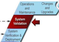 In
this step: After the ITS system has passed system
verification and is installed in the operational environment, the system
owner/operator, whether the state DOT, a regional agency, or another entity,
runs its own set of tests to make sure that the deployed system meets the
original needs identified in the Concept of Operations.
In
this step: After the ITS system has passed system
verification and is installed in the operational environment, the system
owner/operator, whether the state DOT, a regional agency, or another entity,
runs its own set of tests to make sure that the deployed system meets the
original needs identified in the Concept of Operations.
| OBJECTIVES |
|
|---|---|
| INPUT
Sources of Information |
|
| PROCESS
Key Activities |
|
| OUTPUT
Process Results |
|
| Review
Proceed only if you have: |
|
A few readers may be surprised to see that there is another step in the "V" between initial deployment and operations and maintenance. After all, in the last few chapters we have already verified that the system meets all of its requirements, installed the system and trained the users, and the customer has successfully conducted acceptance tests and formally accepted the system. Aren't we done?
The answer is: yes and no. Yes, the system has been put into operation and is beginning to be used for its intended purpose. No, we aren't done. Now that the system is beginning to be used in the operational environment, we have our first good opportunity to measure just how effective the system is in that environment (i.e., system validation).
Figure 30: Validation Occurs Throughout the Systems Engineering Process
In systems
engineering, we draw a distinction between verification and validation.
Verification confirms that a product meets its specified requirements.
Validation confirms that the product fulfills its intended use. The majority
of system verification can be performed before the system is deployed.
Validation really can't be completed until the system is in its operational
environment and is being used by the real users. For example, validation of a
new signal control system can't really be completed until the new system is in
place and we can see how effectively it controls traffic.
Of course, the last thing we want to find is that we've built the wrong system just as it is becoming operational. This is why the systems engineering approach seeks to validate the products that lead up to the final operational system to maximize the chances of a successful system validation at the end of the project. This approach is called in-process validation and is shown in Figure 30. As depicted in the figure, validation was performed on an ongoing basis throughout the process:
Since validation was performed along the way, there should be fewer surprises during the final system validation that is discussed in this step. The system will have already been designed to meet the user's expectations, and the user's expectations will have been set to match the delivered system.
The system validation is the responsibility of the system owner and will typically be performed by the system users.
It is
important to think about the desired outcomes and how they will be measured
early in the process because some measures may require data collection before
the system is operational to support "before and after" studies. For example,
if the desired outcome of the project is an improvement in incident response
times, then data must be collected before the system is installed to measure
existing response times. This "before" data is then compared with data
collected after the system is operational to estimate the impact of the new
system. Even with "before" data, determining how much of the difference
between "before" and "after" data is actually attributable to the new system is
a significant challenge because there are many other factors involved. Without
"before" data, validation of these types of performance improvements is
impossible.
In addition to objective performance measures, the system validation may also measure how satisfied the users are with the system. This can be assessed directly using surveys, interviews, in-process reviews, and direct observation. Other metrics that are related to system performance and user satisfaction can also be monitored, including defect rates, requests for help, and system reliability. Don't forget the maintenance aspects of the system during validation – it may be helpful to validate that the maintenance group's needs are being met as they maintain the system.
Detailed validation procedures may also be developed that provide step-by-step instructions on how support for specific user needs will be validated. At the other end of the spectrum, the system validation could be a set time period when data collection is performed during normal operations. This is really the system owner's decision – the system validation can be as formal and as structured as desired. The benefit of detailed validation procedures is that the validation will be repeatable and well documented. The drawback is that a carefully scripted sequence may not accurately reflect "intended use" of the system.
The
measurement of system performance should not stop after the validation period.
Continuing performance measurement will enable you to determine when the system
becomes less effective. The desired performance measures should be reflected
in the system requirements so that these measures are collected as a part of
normal system operation as much as possible. Similarly, the mechanisms that
are used to gauge user satisfaction with the system (e.g., surveys) should be
used periodically to monitor user satisfaction as familiarity with the system
increases and expectations change.
Frequently, the way in which the system is used will evolve during initial system operation. Significant departures from anticipated procedures should also be noted and documented in the Concept of Operations. For example, consider an HOV reversible lane facility that uses system detectors to verify that all vehicles have exited the facility. During system operation, the agency may find that the reliability of system detectors is not as high as anticipated. To compensate, the agency adjusts its operating procedures to perform a physical tour of the facility prior to opening it up in the opposite direction. The agency should amend its ConOps to reflect this new way of operating the HOV facility.
Deficiencies
of the project development process should also be reviewed to determine where
the process may have fallen down, so that an improved process can be used on
the next project. Without worrying about attribution to individuals, determine
how a significant deficiency slipped through the process. Were the needs not
properly specified? Were requirements incorrectly specified based on the
needs? If so, were there opportunities for the stakeholders to walk through
the requirements and identify the problem? A "lessons learned" review of the
project development process at the conclusion of the system validation can be
very valuable.
System validation should result in a document trail that includes an up-to-date Validation Plan; validation procedures (if written); and validation results, including disposition of identified deficiencies. There are several industry and government standard outlines for validation plans, including IEEE Standard 101218, which is intended for software verification and validation but is also applicable to broader system verification and validation. Note that this standard covers both verification and validation plans with a single outline.
There are few good examples of system validations that have been performed for ITS projects. Some of the best examples are evaluations that have been performed for field operational tests (FOTs), and other evaluations that have looked in detail at the benefits of ITS. For example, the evaluation of the ORANGES Electronic Payment Systems FOT initially identified system goals and then related them to quantitative and qualitative performance measures, as shown in Table 16. Each of the performance measures was then evaluated, in many cases using before-and-after study techniques, to determine whether the system goals were achieved. Figure 31 shows results supporting the transponder market penetration goal (Goal 2). This evaluation report is a good example of many validation techniques, including the collection of baseline data, before-and-after studies, statistical analysis, evaluation of other causal factors, and interview and survey activities.
Table 16: ORANGES Evaluation Goals and Performance Measures
| FOT Evaluation Goal | Measure |
|---|---|
| 1. Increase parking revenue |
|
| 2. Increase transponder market penetration |
|
| 3. Reduce transaction times |
|
| 4. Increase prepaid revenue share |
|
| 5. Reduce monthly pass distribution costs |
|
| 6. Increase automated payment equipment uptime |
|
| 7. Cardholders use the joint account |
|
8. Understand customer perceptions
|
|
9. Understand operations/maintenance staff perceptions, including:
|
|
10. Understand planning/management staff perceptions, including:
|
|
11. Understand interagency perceptions, including:
|
|
Figure 31: ORANGES Evaluation – Cumulative Transponders Issued
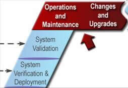 In this step: Once the customer has
accepted the ITS system, the system operates in its typical steady state.
System maintenance is routinely performed and performance measures are
monitored. As issues, suggested improvements, and technology upgrades are
identified, they are documented, considered for addition to the system
baseline, and incorporated as funds become available. An abbreviated version
of the systems engineering process is used to evaluate and implement each
change. This occurs for each change or upgrade until the ITS system reaches
the end of its operational life.
In this step: Once the customer has
accepted the ITS system, the system operates in its typical steady state.
System maintenance is routinely performed and performance measures are
monitored. As issues, suggested improvements, and technology upgrades are
identified, they are documented, considered for addition to the system
baseline, and incorporated as funds become available. An abbreviated version
of the systems engineering process is used to evaluate and implement each
change. This occurs for each change or upgrade until the ITS system reaches
the end of its operational life.
| OBJECTIVES |
|
|---|---|
| INPUT
Sources of Information |
|
| PROCESS
Key Activities |
|
| OUTPUT
Process Results |
|
| Review
Proceed only if you have: |
|
Now that the ITS system is up and running, it enters a "steady state" period that lasts until the system is retired or replaced. During this period, operators, maintainers, and users of the system may identify issues, suggest enhancements, or identify potential efficiencies. New releases of hardware and software will be installed and routine maintenance will be performed. Approved changes and upgrades are incorporated into the system baseline using the systems engineering process, as shown in Figure 32. O&M personnel might also identify process changes that may streamline O&M activities. All changes to the processes should be documented.
Figure 32: Changes/Upgrades Performed Using Systems Engineering
Successful operations and maintenance of the system will lead to customer and user satisfaction; for example, the CCTVs will be online and fully functional at all times; rush-hour drivers will be able to obtain accurate, up-to-the-minute speed, accident, and construction reports before they head out the door; and transit vehicles will arrive on time. This is when the system benefits are realized.
In most systems, operations and maintenance is where the lion's share of life-cycle costs are incurred. The key activities are performed periodically unless a change is considered severe and affects system performance dramatically.
A
database that holds information about all user support inquiries can help you
to review the types of calls that were received and to notice trends. If there
seems to be a recurring problem or confusion about some aspect of the system,
it could mean that a system modification should be considered.
All proposed changes should be prioritized and will require careful cost estimates, schedules, planning, testing, and coordination with operations and maintenance prior to installation. Each approved change will require a new system release level and should be coordinated between the O&M and development teams.
Each potential change to the
system should be assessed by the affected stakeholders and the project sponsor
to determine whether or not it should be incorporated. Before approving the
change, you should clearly
understand and document the effect that it will have on other parts of the
system, on the operation of the system as a whole, and on the maintenance of
the system. If you make this assessment early on by following the systems
engineering process, you won't discover a problem months later in the lab when
the impact on the schedule and budget will be significantly higher.
Changes
are approved and managed using the configuration management process defined in
Section 5.4. You should use the systems engineering process, from Concept of
Operations through design, verification, and installation, to add any approved
change to the system. Basically, each change requires another, possibly
abbreviated, pass through the "V". Approved changes are typically aggregated
into builds or releases, although you may want to introduce particularly
complex changes individually.
Each build or release should be subjected to thorough verification testing prior to installation. There are many stories of "changes that affected only a few lines of code" that ultimately resulted in operational failure. It is important to run regression tests that verify that a seemingly minor change in one part of the system didn't have an unexpected effect on another part of the system. Statements like "I didn't change that area so there is no need to test it" should be a red flag.
In many
cases, the development and test lab that was available during the initial
system development may not be available once the system has been deployed. (It
might even be the system that was deployed!) Therefore, it's common to
establish a test environment to test software product upgrades or minor fixes
without interfering with the current operational system.
This
is one area where state of the practice lags a bit in ITS. It is common for
agencies to require good configuration management practices during system
development but to lose configuration control after the system is delivered.
For example, if you want to know the configuration of a field controller at a
particular location, you will have to take a trip to the field and have a look
inside the cabinet at many agencies.
Consider
using a database tool or a similar property management application to help you
keep track of all equipment, together with maintenance records, maintenance
schedules, and so forth. Check it weekly and schedule the maintenance
required.
The current system configuration, including hardware, software, and operational information, must be documented and maintained. A complete record of all system changes should also be documented and readily available. This is especially helpful when trying to duplicate an anomaly identified by a user or operator.
System performance reports should be generated, both from any installed automated performance monitors and from user-support calls received. Trend analysis reports can be generated and reviewed to identify system deficiencies.
Figure 33: Kentucky ITS M&O Plan Best Practices
Operations and Maintenance Plans
The Kentucky Transportation Center developed a Maintenance and Operations Plan for ITS in Kentucky that provides recommendations for supporting and coordinating ITS maintenance and operations activities throughout the Kentucky Transportation Cabinet. It inventories ITS equipment and systems, identifies national best practices for operations and maintenance (see Figure 33), assesses current maintenance and operations practices in Kentucky, and makes recommendations. Many of the recommendations and best practices identified in the report will be relevant to other agencies. This broad agency-wide plan complements the detailed procedures that are used to operate and maintain individual systems.
Operations and Maintenance Procedures
Operations and maintenance procedures are detailed and don't make particularly good reading unless you actually operate and maintain one of these systems, in which case they are indispensable. These manuals will be subject to relatively frequent changes as personnel will find errors and new and better ways to operate and maintain the system. A short excerpt from the CHART II O&M Procedures is shown in Figure 34.
Figure 34: CHART II O&M Procedures
Change and Upgrade Plans
Metro Transit in Seattle, Washington, upgraded its existing Transit AVL system to support transit traveler information systems as part of the Smart Trek program. To support this upgrade, detailed cost estimates were made based on systems engineering analysis of the AVL enhancements that would be required to support the traveler information objectives of the Smart Trek project. The estimate is shown in Table 17.
Table 17: Metro Transit AVL System Upgrade
 In
this step: Operation of the ITS system is periodically
assessed to determine its efficiency. If the cost to operate and maintain the
system exceeds the cost to develop a new ITS system, the existing system
becomes a candidate for replacement. A system retirement plan will be
generated to retire the existing system gracefully.
In
this step: Operation of the ITS system is periodically
assessed to determine its efficiency. If the cost to operate and maintain the
system exceeds the cost to develop a new ITS system, the existing system
becomes a candidate for replacement. A system retirement plan will be
generated to retire the existing system gracefully.
| OBJECTIVES |
|
|---|---|
| INPUT
Sources of Information |
|
| PROCESS
Key Activities |
|
| OUTPUT
Process Results |
|
| Review
Proceed only if you have: |
|
Systems are retired from service for a variety of reasons. Perhaps the system is being replaced by a newer system, or maybe the Concept of Operations has changed such that stakeholder needs are going to be met in an alternative manner that will no longer require use of the system. For example, the emergency call boxes that currently dot many of the nation's highways are beginning to be retired because their usage has decreased dramatically due to widespread use of cell phones. Many of the first-generation ITS systems are twenty years old and approaching the end of their useful life. Regardless of the reason for the retirement of the system, you should make sure that everything is wrapped up (e.g., hardware and software inventory identified for disposal is audited, final software images are captured, and documentation is archived), the contract is closed properly, and the disposal of the system is planned and executed.
This step represents the end of the system life cycle – the retirement and disposal of the ITS system. An important characteristic of the systems engineering process is the planning of all events; the retirement of the system should be planned as well.
The retirement plan should include a complete inventory of all software and hardware, final system and documentation configurations, and other information that captures the final operational status of the system. This should include identification of ownership so that owners can be given the option to keep their equipment and use it elsewhere. It should also include how the system and documentation will be disposed of, including an assessment and plan if special security measures should be in place or if there are environmental concerns that might dictate the site of disposal. You should also plan to erase the content of all storage devices to protect any personal data that might pose privacy concerns. The retirement plan should be reviewed and approved by all parties, including the agency or contractor providing O&M, the owner of the system (if different), and other key personnel.
If the system to be retired is not documented as well as it should be, steps are taken to capture all necessary data and reverse engineer interfaces and any system configuration information that is needed to support a replacement system. Existing databases may need to be exported and translated into a format suitable for the replacement system.
The next activity is to execute the retirement plan and record the results. It's also a good idea to hold a "lessons learned" meeting that includes suggested system improvements. All recommendations should be archived for reference in future system disposals. The O&M contract should be officially closed out if one exists.
A system retirement plan will be generated that describes the strategy for removing the system from operation and disposing of it. Its execution will result in the retirement of the ITS system. The final system configuration, including hardware, software, and operational information, will be documented and archived, together with a list of "lessons learned".
TOC Previous Page Next Page