Automated Driving Systems (ADS) Operational Behavior and Traffic Regulations Information – Proof-of-Concept Demonstration ReportCHAPTER 3. PROOF-OF-CONCEPT DEMONSTRATIONThis chapter describes a proof-of-concept demonstration of the operations of an automated driving system (ADS)-equipped vehicle with connection to the traffic regulations framework prototype presented in chapter 2. OBJECTIVEThe objective of the demonstration is to show how traffic laws and regulations, as stored in the traffic regulations framework, can be processed by a typical automated driving system (ADS) platform and subsequently affect the operational behavior of ADS-equipped vehicles. The demonstration is conducted in an automated driving (AD) simulator equipped with additional development modules that help ADS-equipped vehicles process traffic regulations information for vehicle behavior planning and control. Specifically, the tasks of the demonstration are as follows:
SIMULATION PLATFORM – CARLACARLA is an open-source simulation software designed specifically for automated driving systems (ADS). It is frequently referred to as an AD simulator. The platform allows for extensive and detailed customization of the environment, actors (any created entity), and map generation, among others. CARLA is grounded on Unreal Engine to run the simulation and uses the OpenDRIVE standard to define roads and urban settings. Control over the simulation is granted through an application programming interface (API) handled in Python® and C++. The CARLA simulator has a scalable client-server architecture, as illustrated in figure 14. The server is responsible for everything related to the simulation itself, such as sensor rendering, computational physics, and updates on the world-state and its actors. The client side consists of a sum of client modules controlling the logic of actors on the scenes and setting world conditions. This is achieved by leveraging the CARLA API (in Python or C++) layer that mediates between the server and the client and is constantly evolving to provide new functionalities. 
© 2021 http://carla.org/ Figure 14. Illustration. CARLA Core Simulator and Python®
application programming interfaces.
Key features and elements of CARLA include the following:
The traffic laws and regulations can be incorporated as surrounding traffic environments through Python APIs and sent to the subject ADS vehicles directly. Then, the ADS planning and control modules will take this information as input. This inupt being a part of the dynamic world model that has been created by the environment sensing and perceiving modules, to plan and implement the maneuvers that meet the requirements prescribed by traffic laws and regulations. SIMULATION TESTING WORKFLOW AND INTERFACESIn this project, we aim to connect the traffic laws and regulations database with a standard automated driving platform to serve as a proof-of-concept. The upper part of figure 15 shows a standard ADS software platform, including four stacks: sense, plan, control, and actuation. The ADS Regulations Database can be local on the vehicle storage (downloaded before the trip) and/or accessed in real time through vehicular communications (e.g., when the vehicle enters a new geographic area). The vehicle SENSE Stack generates the location of the vehicle and then extracts the most relevant laws and regulations stored in the ADS regulations database. The queries from the database are based on vehicle jurisdictions and boundaries and the vehicle’s driving situation. The database then generates allowed ADS regulation-related behavior. This behavior output will feed to the behavior planning module of the PLAN Stack and this information will integrate into the overall behavior planning software module. Therefore, the generated ADS behavior will be constrained by the relevant ADS regulations. 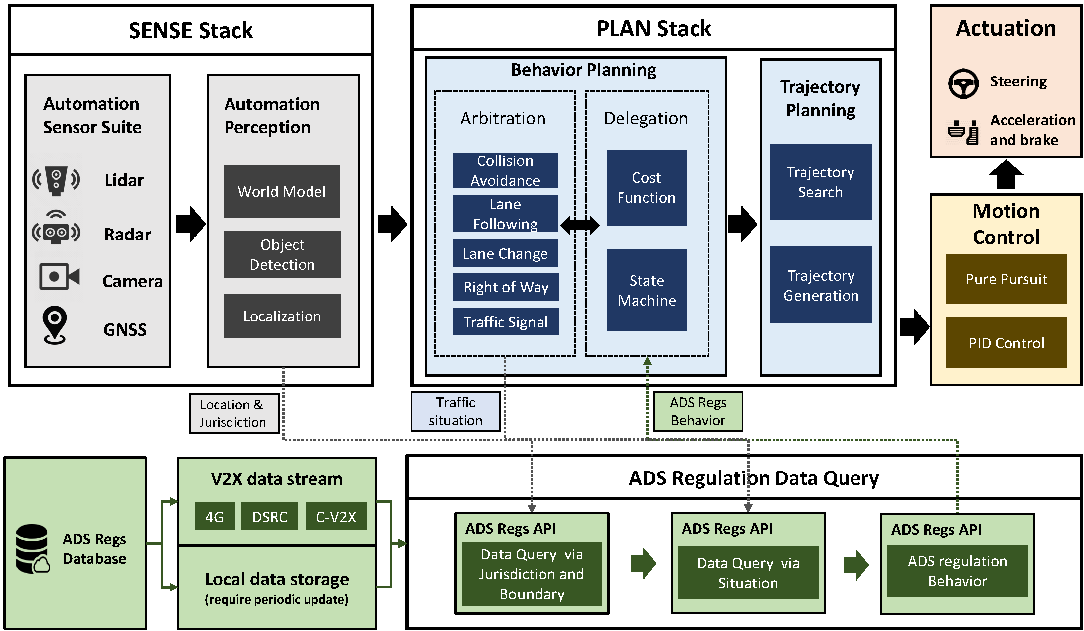
Source: FHWA. Figure 15. Illustration. Automated driving system latform architecture with traffic regulations database.
The workflow for architecture implementation includes the following five steps or components and will be discussed in subsequent subsections:
Access Regulation DataThe first step in the workflow is to access and query ADS regulation data by location using a combination of global positioning system (GPS) coordinates and outputs of the perception and localization software module of ADS, as illustrated in figure 16. In our CARLA simulation example, we map some real-world coordinates to our simulated world in the database for demonstration purposes. Through the ADS regulations API, the vehicle retrieves a comprehensive list of ADS regulations relevant to the current location. Some examples include "Stop at intersection with stop sign" and "Turn right at the intersection with the green indication." Some of these regulations are standard, like the former example, and regular ADS platform can already handle those regulations. However, the latter regulation is location-specific, and the ADS platform will need to comprehend this information in its trajectory planning. 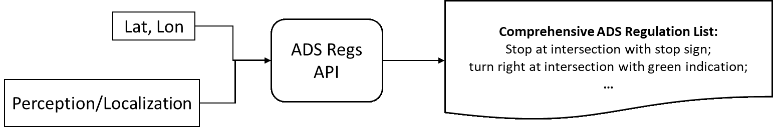
Source: FHWA. Figure 16. Diagram. Workflow for accessing regulations data.
In this workflow diagram, latitude and longitude along with perception/location feed into the ADS regulations API, which feeds into the comprehensive ADS regulation list: Stop at intersection with stop sign; turn right at intersection with green indications.
Maintain a Regulation List for the Current LocationAs shown in figure 17, the vehicle constantly queries regulation information relevant to the current location and updates the regulation list in the temporary memory if some regulations are not applicable anymore; e.g., outside the applicable range. While this update does not need to operate at the regular control update frequency (e.g., 0.1 seconds), this list needs to be updated every few seconds to ensure the latest regulation lists are used in ADS behavior planning. 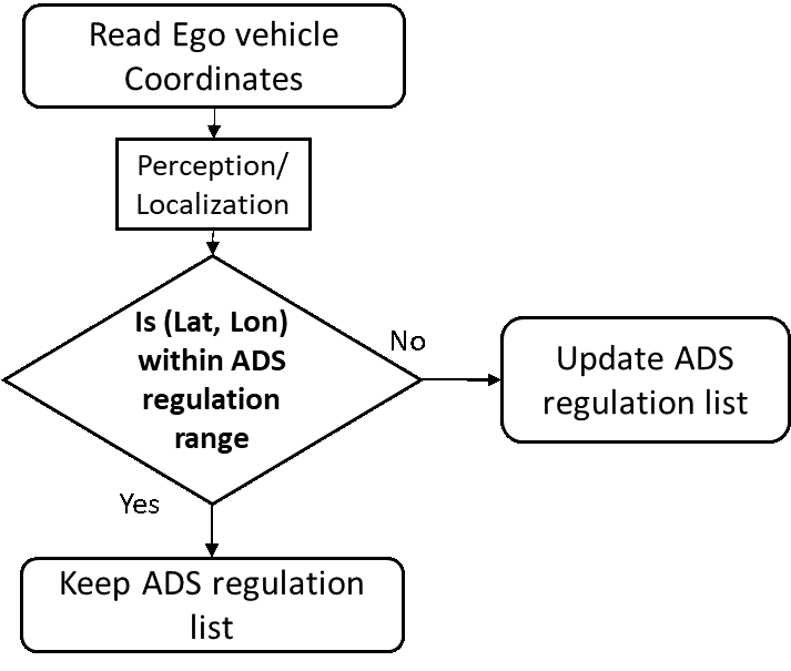
Source: FHWA. Figure 17. Diagram. Worflow for maintaining legal regulation list in automated driving systems for current vehicle location.
This process workflow diagram proceeds as follows: Read Ego vehicle coordinates feeds into perception/localization, followed by the determination of whether the latitude and longitude are within the ADS regulation range. If yes, keep the ADS regulation list; if no, update the ADS regulation list.
Generate Regulation Action Vector for Automated Driving System RegulationsThe third component is to use the extracted list of regulations to generate the ADS Regulation Action Vector, as shown in figure 18. All the regulation languages in the ADS regs database, originally from the UVC, share a similar language structure: action, direction, road situation, and intersection situation. These four components are then added together to generate the Regulation Action Vector. In this demonstration, this Regulation Action Vector is compared to the ADS-equipped vehicle intent vector to determine if the ADS behavior is legal. 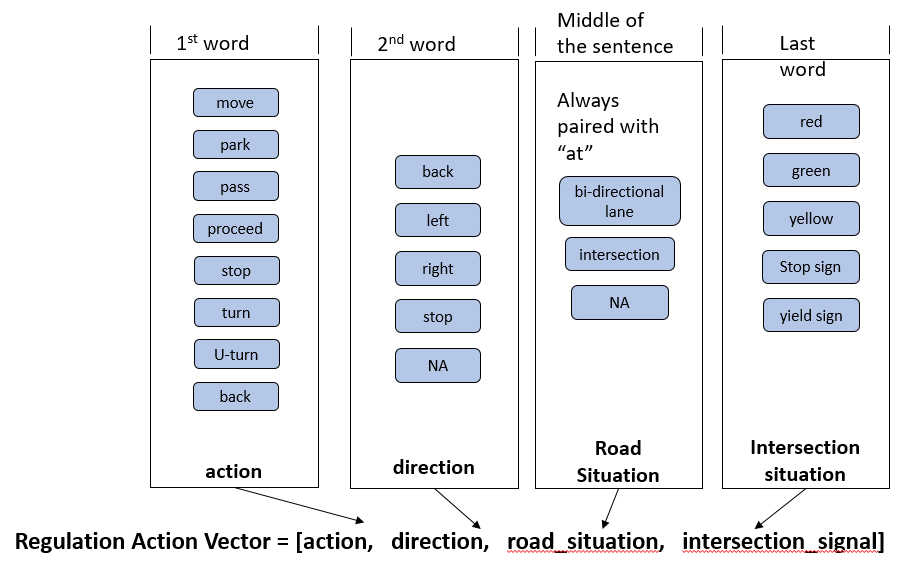
Source: FHWA. Figure 18. Diagram. Generate regulation action vector for automated driving system regulations.
Vectorize the Vehicle’s Intention as Intention Action VectorThe fourth step is to summarize the vehicle’s current intention (i.e., intended behavior from the baseline behavior planning module if the traffic regulations are not considered) into an Intention Action Vector. Generally, the behavior includes information such as future waypoints or target trajectories (which include future locations and speeds). As shown in figure 19, a program is created to turn the planned waypoints and trajectories into the Intention Action Vector, which will then be compared with the Regulation Action Vector. 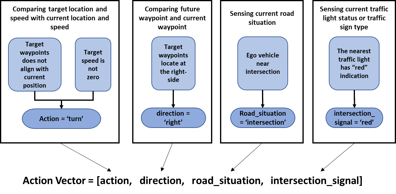
Source: FHWA. Figure 19. Diagram. Vectorize the vehicle’s intention as an intention action vector.
Determine the Vehicle Behavior’s LegalityThe last step of the workflow is to compare two vectors, (ADS Regulation Action Vector and Intention Action Vector), as shown in figure 20. If there is a match (i.e., the Intention Vector is in the set of Regulation Action Vectors), the intention is legal. If not, the intention is illegal. If illegal, the behavior or trajectory planner will re-plan the behavior and trajectory. This can be done in multiple ways. For example, the PLAN Stack can generate many multiple candidates for the next behavior and trajectory and compare each of the candidates to the ADS Regulation Action Vector to determine if the plan is legal. The final determination of behavior and trajectory can be a combination of legality and efficiency, safety, and other performance measures. In this process, the illegal behavior will be significantly punished and not selected by the ADS Plan Stack. While this or other methods can be used for future real-world deployment, we use this method for simplicity and clarity in this proof-of-concept demonstration. 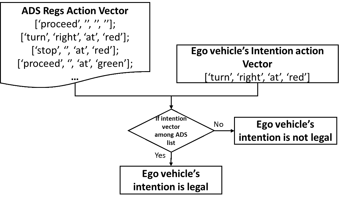
Source: FHWA. Figure 20. Diagram. Workflow for determining the vehicle behavior’s legality.
TESTING SCENARIOS AND RESULTSA proof-of-concept demonstration of the traffic regulations database prototype is demonstrated with the above-mentioned simulation-based testing platform. The demonstration is performed under two different environments: freeways and urban streets with signalized intersections, for the purpose of testing two different traffic regulations, i.e., freeway left-lane use and right-turn-on-red (RTOR), respectively. In each of the simulations, the proof-of-concept ADS software in the simulation is designed to operate under the specific roadway types with different operational rules. For example, during the urban street testing, the ADS understands the traffic lights and can act according to the light indications. This means that the ADS are designed to operate under specific components of the operational design domain (ODD) in each simulation. Note that, in this study, the traffic regulations are not a pre-defined ODD component and the ADS considers the regulations information as a component of the dynamic world model, from which the ADS will generate planned behavior and trajectories. Demonstration WorkflowIn each simulation, the overall workflow is described below:
Specifically, the workflow for each of the ADS-equipped vehicle agents in the simulation is described as below:
Please refer to chapter 2 for descriptions of the interfaces between the traffic regulations database and the simulated ADS platform. AUTOMATED DRIVING SYSTEM TESTING RESULTSSimulation results and discussions are presented in this section for each of the two simulation scenarios. Intersection Right Turn on RedThe first scenario concerns traffic regulations at signalized intersections on urban streets. The focus being whether RTOR is allowed at intersections when the traffic light is red. The specific details of the scenario are as follows:
Figure 21 illustrates the simulation demonstration and results. Figure 21(a) shows an ADS-equipped vehicle is approaching the signalized intersection with all traffic light indications in red. In this figure, the scenario shows that the ADS comprehends that RTOR is not allowed at this intersection. The X marks in the figure are waypoints along the vehicle's planned future trajectory. Even though the vehicle intends to cross the stop bar and turn right, the active regulation of no RTOR makes the ADS replan the trajectory and it can be seen from the figure that the last waypoint ends at the stop bar, indicating that the vehicle has planned a trajectory to stop at the stop bar. In figure 21(b), which is the same simulation under the same scenario of RTOR not allowed, the vehicle waits until the green indication to replan the trajectory to make a right turn and complete its intention. In figure 21(c), which is under a different scenario of RTOR allowed, even when the red traffic light indication is on, the vehicle stops at the intersection briefly for safety purposes (the default logic of the simulated baseline ADS platform). The vehicle then continues the right-turn maneuver by following the originally planned trajectory, with the understanding of RTOR allowed when the vehicle was approaching the intersection with the red indication on. 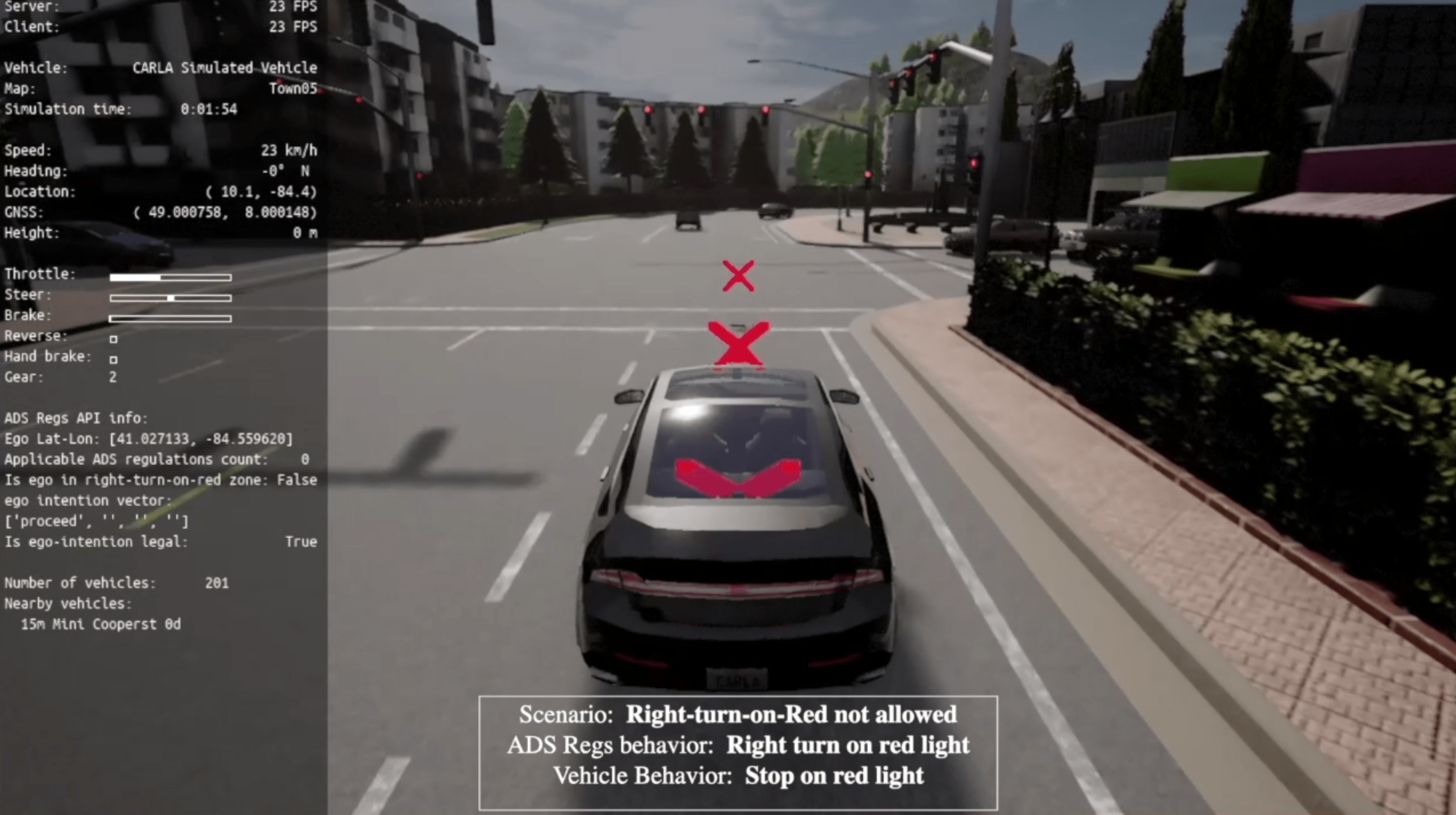
(a) Vehicle approaching and stopping at red light. 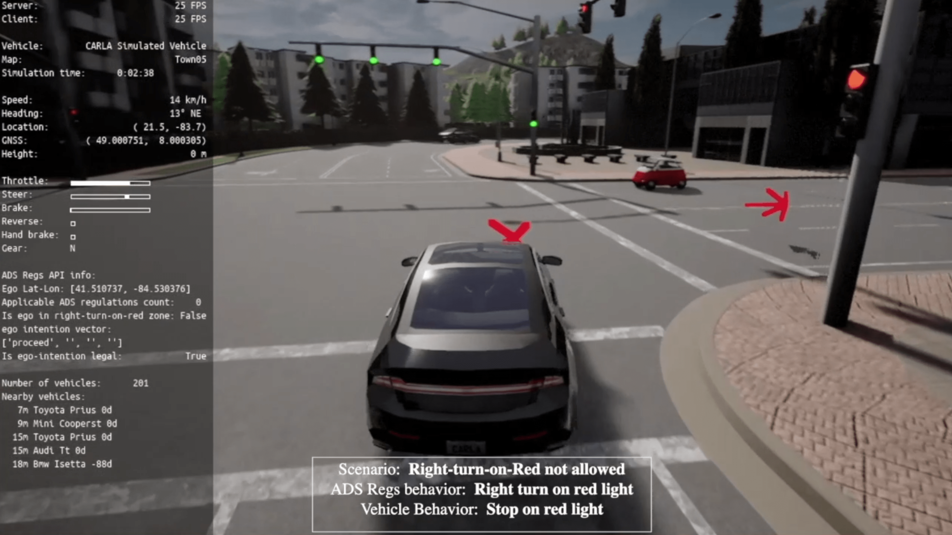
(b) Vehicle starting new waypoints until green. 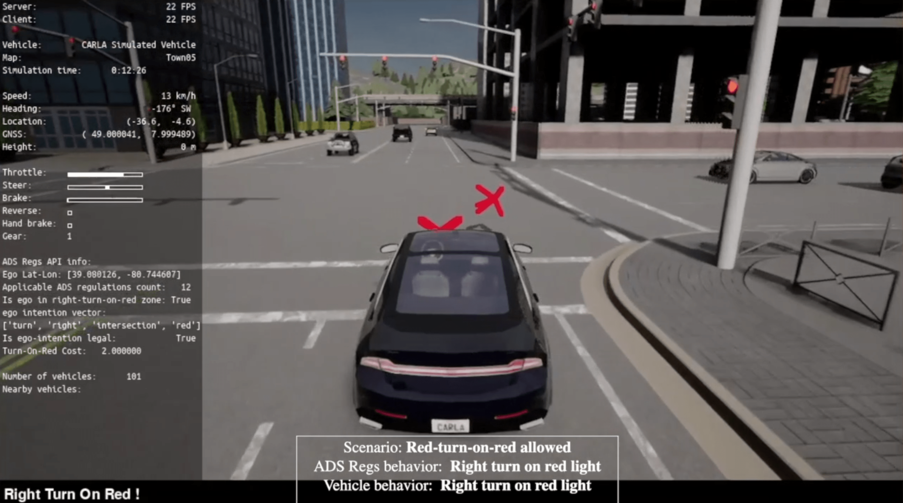
(c) Vehicle starting new waypoints with red. Source: FHWA. Figure 21. Illustration. Intersection right-turn-on-red demonstration.
Simulated illustration of a vehicle approaching a red light. A panel at left illustrates information about the simulation. Two consecutive x marks are overlaid directly ahead of the vehicle indicating a forward path. The scenario description indicates a right turn on red is not allowed. ADS Regulations behavior is right turn on red light. Vehicle behavior is stop on red light.
Simulated illustration of a at an intersection with a green light; a panel at left shows the calculations it uses to replan the trajectory to make a right turn and complete its intention. An x mark is overlaid immediately in front of of the vehicle, and a right-pointing arrow indicates the anticipated direction of the vehicle after the turn. The scenario descriptions is the same as that for figure 21a.
Vehicle stopped at a red light prior to initiating a right turn. A panel at left illustrates information about the simulation. Two x consecutive marks are overlaid immediately in front of of the vehicle, with the x farthest away positioned to the right of the x that is closer. The scenario description indicates a right turn on red is allowed. ADS Regulations behavior is right turn on red light. Vehicle behavior is stop on red light.
Freeway Left Lane UseThe second scenario concerns traffic regulations at freeway segments, i.e., whether the left lane on a multi-lane freeway roadway can be used as a general-purpose traveling lane or overtaking lane only. The specific details of the scenario are as follows:
The simulation demonstration and results are shown in figure 22. In figure 22(a), an ADS-equipped vehicle initiated a lane change to the left because of a slow-moving vehicle in the front. This overtaking behavior is originally embedded in the simulated ADS platform as a baseline function for driving efficiency. In figure 22(b), the vehicle has completed the lane-change maneuver and continues to plan trajectories that keep itself in the left lane. This is because the data from the traffic regulations database indicate that the left lane can be used as the general traveling lane, and there is also no motivation (e.g., efficiency saving to overtake slow-moving front vehicle) for this vehicle to change lanes back to the middle lane. This is also the default logic in the simulated ADS platform. However, in figure 22(c), the left lane can only be used as the overtaking lane, and therefore, the vehicle replans its behavior and trajectory to change the lane back to the middle lane, even though there are no slow-moving vehicles in front of the vehicle in the left lane. This is because the PLAN Stack imposes a heavy penalty on the trajectories that keep the vehicle in the left-most lane, and therefore the ADS will then select a trajectory back to the middle lane that is rated higher by the PLAN Stack. 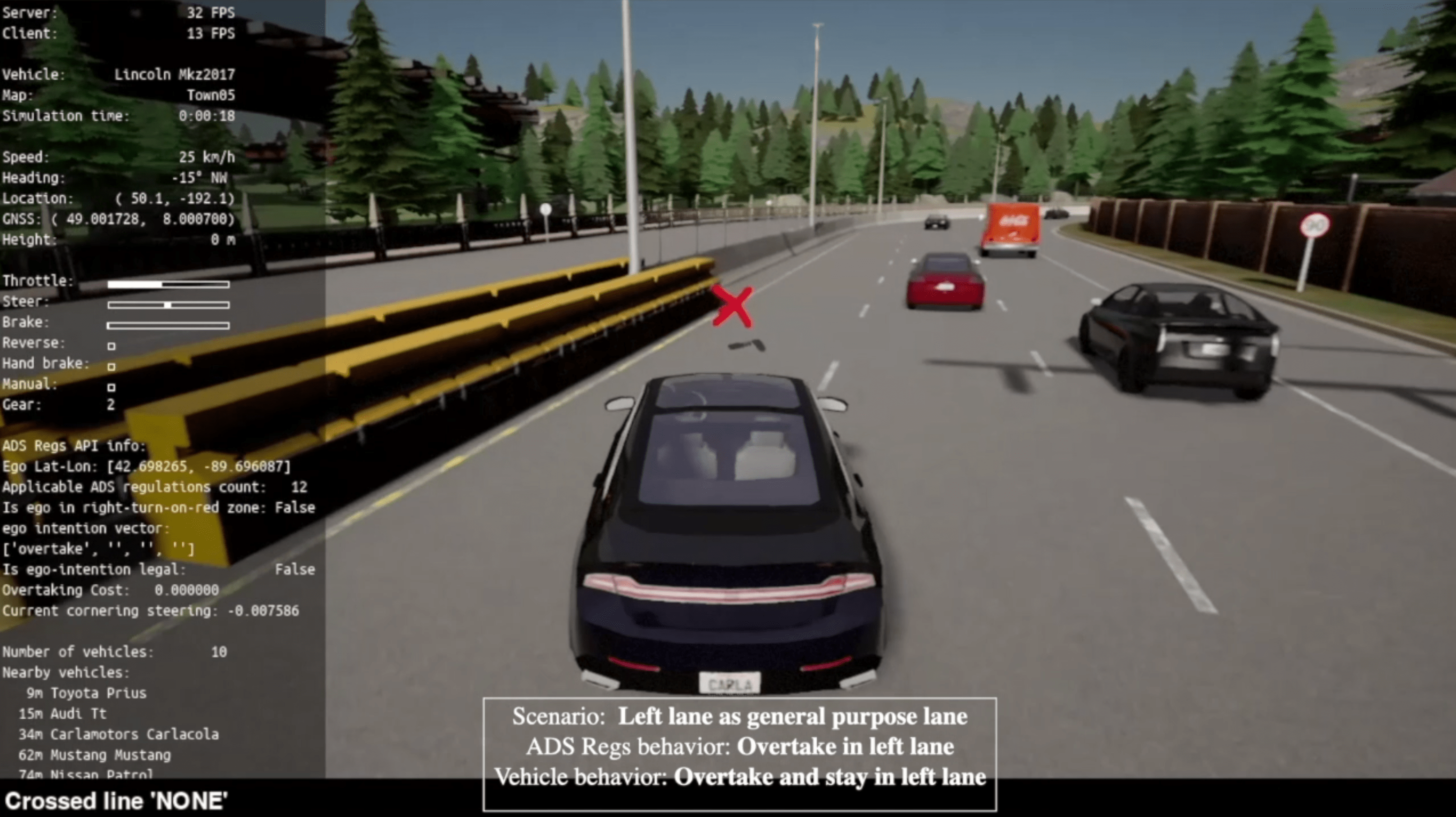
(a) Vehicle initiating lane change for overtaking. 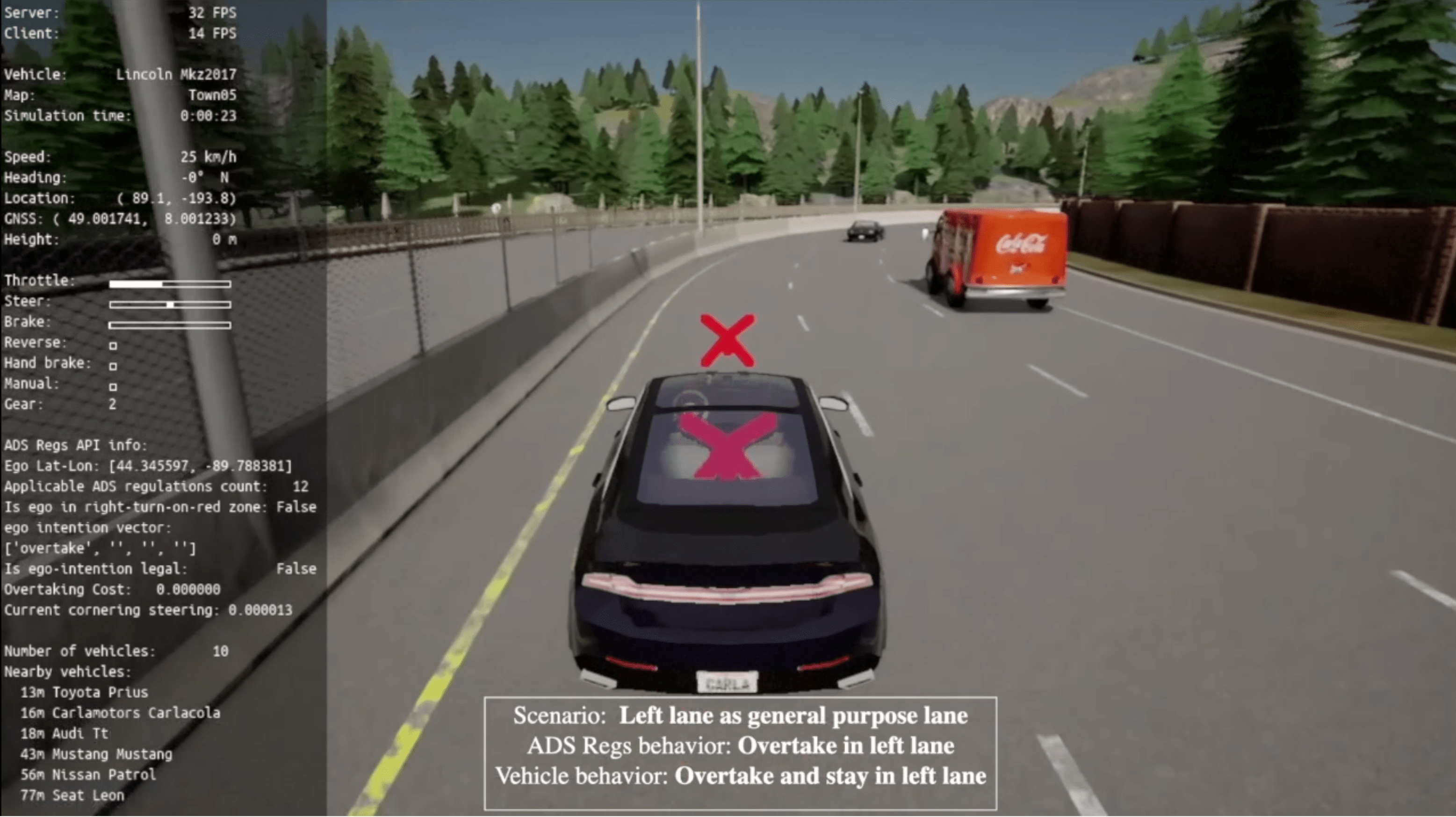
(b) Vehicle operating in the left lane after overtaking. 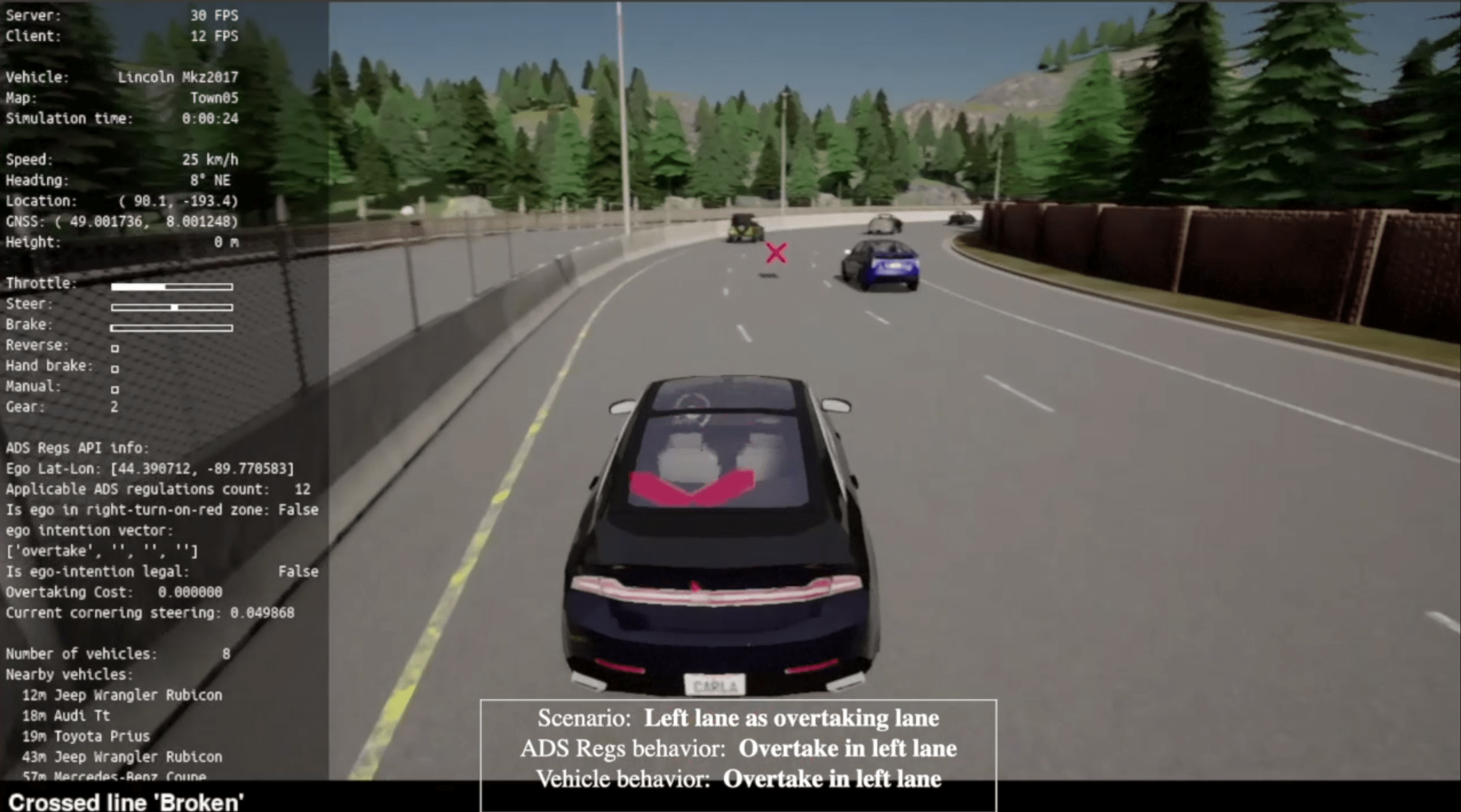
(c) Vehicle returning to the right lane after overtaking. Source: FHWA. Figure 22. Illustration. Freeway overtaking demonstration.
The demonstration successfully connects the traffic regulations database prototype with the simulated example ADS platform. More importantly, the simulation shows the necessity of providing such data to ADS-equipped vehicles for them to operate safely and legally on national highways. The demonstration of both scenarios also shows the generation of unique operational behaviors when the same ADS software operates on the same highway facilities both with and without the regulation being accounted for. The demonstration indicates the need for both IOOs and ADS developers to explicitly consider the impacts of traffic regulations on ADS operational behavior. As proven in this study, IOOs and ADSs need to provide streamlined interfaces in the development of ADS platforms, traffic regulation database, and the entire ADS ecosystem. SIMULATION REPOSITORYThe simulation source codes, along with the traffic regulations database, are open to the public through the GitHub repository7 for the simulation scripts, videos, and documentation. The codes are designed to demonstrate the implementation of integration between traffic laws and regulations database framework and ADS-equipped vehicle platform. The codes for both the intersection and freeway scenarios are uploaded. The ADS-equipped vehicles are modeled at different locations using the same database. The instructions for setting up the simulation environment are also provided on the GitHub repository. 7 GitHub. 2021. “ads-traffic-regs.” (website). https://github.com/usdot-fhwa-stol/ads-traffic-regs/tree/cherneysp-initial, last accessed December 7, 2021. [ Return to Return to Note 7 ] |
|
United States Department of Transportation - Federal Highway Administration |
||