Traffic Signal Timing Manual
Contact Information: Operations Feedback at OperationsFeedback@dot.gov
This publication is an archived publication and replaced with the Signal Timing Manual - Second Edition.
CHAPTER 5
BASIC SIGNAL TIMING PROCEDURE AND CONTROLLER PARAMETERS
TABLE OF CONTENTS
- 5.0 BASIC SIGNAL TIMING PROCEDURE AND CONTROLLER PARAMETERS
- 5.1 Terminology and Key Definitions
- 5.2 Modes of Traffic Signal Operation and Their Use
- 5.2.1 Pre-timed Control
- 5.2.2 Semi-Actuated Control
- 5.2.3 Fully-Actuated Control
- 5.3 Phase Intervals and Basic Parameters
- 5.3.1 Vehicular Green Interval
- 5.3.2 Vehicular Change and Clearance Intervals
- 5.3.3 Pedestrian Timing Intervals
- 5.4 Actuated Timing Parameters
- 5.4.1 Phase Recalls
- 5.4.2 Passage Time
- 5.4.3 Simultaneous Gap
- 5.4.4 Dual Entry
- 5.5 Volume-Density Features
- 5.5.1 Gap Reduction
- 5.5.2 Variable Initial
- 5.6 Detection Configuration and Parameters
- 5.6.1 Delay
- 5.6.2 Extend
- 5.6.3 Carryover
- 5.6.4 Call
- 5.6.5 Queue
- 5.7 Guidelines for Time-Base Controls
- 5.8 References
LIST OF TABLES
- Table 5-1. Relationship between intersection operation and control type
- Table 5-2 Factors considered when setting the minimum green interval
- Table 5-3 Typical minimum green interval duration needed to satisfy driver expectancy
- Table 5-4 Typical minimum green interval duration needed to satisfy queue clearance
- Table 5-5 Example values for maximum green duration
- Table 5-6 Maximum green duration as a function of cycle length and volume
- Table 5-7 Duration of change period intervals
- Table 5-8 Pedestrian walk interval duration
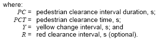
- Table 5-9 Pedestrian clearance time
- Table 5-10 Passage time duration for presence mode detection
- Table 5-11 Minimum gap duration for presence mode detection
- Table 5-12 Gap reduction parameter values
LIST OF FIGURES
- Figure 5-1 Users and the actuated signal timing parameters that determine phase length
- Figure 5-2 Settings that define the duration of a vehicle phase
- Figure 5-3 Application of passage time
- Figure 5-4 Relationship between passage time, gap, and maximum allowable headway
- Figure 5-5 Use of volume-density to change the extension time
- Figure 5-6 Use of Added Initial to modify minimum green
- Figure 5-7 Application of delay timer
- Figure 5-8 Application of extend timer
5.0 BASIC SIGNAL TIMING PROCEDURE AND CONTROLLER PARAMETERS
This chapter documents the principles of basic traffic signal timing at an intersection. Signal timing is a collection of parameters and logic designed to allocate the right-of-way at a signalized intersection. A major focus of this chapter is to describe basic signal timing parameters necessary to operate an intersection and guidelines for selecting values for those parameters. The principles described in this chapter are generally applicable to all signalized intersections. To maximize the usefulness and transferability of the information provided, the chapter uses the terminology defined in current traffic signal control standards, such as National Transportation Communications for ITS Protocol (NTCIP) Document 1202 (1) and National Electrical Manufacturers Association (NEMA) Standards Publication TS 2-2003 (2), with alternative definitions in some cases.
5.1 TERMINOLOGY AND KEY DEFINITIONS
This section identifies and describes basic terminology used within this chapter. Additional terms can be found in the Glossary section of the Manual.
Actuated Signal Control
A type of signal control where time for each phase is at least partially controlled by detector actuations.
Call
An indication within a controller that a vehicle or pedestrian is awaiting service from a particular phase or that a recall has been placed on the phase.
Extend
A detector parameter that increases the duration of a detector actuation by a defined fixed amount.
Gap Out
A type of actuated operation for a given phase where the phase terminates due to a lack of vehicle calls within a specific period of time (passage time).
Interval
The duration of time during which the indications do not change their state (active or off). Typically, one or more timing parameters control the duration of an interval. The pedestrian clearance interval is determined by the pedestrian clearance time. The green interval duration is controlled by a number of parameters including minimum time, maximum time, gap time, etc.
Isolated intersection
An intersection located outside the influence of and not coordinated with other signalized intersections, commonly one mile or more from other signalized intersections.
Minimum Gap
A volume density parameter that specifies the minimum green extension when gap reduction is used.
Minimum Green
A parameter that defines the shortest allowable duration of the green interval.
Minimum Recall
A parameter which results in a phase being called and timed for at least its minimum green time whether or not a vehicle is present.
Movement
Movements reflect the user perspective. Movements can also be broken down into classes (car, pedestrians, buses, LRT, etc.). Typical movements are left, through and right. Movement is an activity in response to a “go” (green ball, green arrow, walk, white vertical transit bar) indication.
Max Out
A type of actuated operation for a given phase where the phase terminates due to reaching the designated maximum green time for the phase.
Passage Time (Vehicle Interval, Gap, Passage Gap, Unit Extension)
A parameter that specifies the maximum allowable duration of time between vehicle calls on a phase before the phase is terminated.
Pedestrian Clearance Interval
Also generally known as “Flashing Don’t Walk” (FDW). An indication warning pedestrians that the walk indication has ended and the don’t walk indication will begin at the end of the pedestrian clearance interval. Some agencies consider the pedestrian clearance interval to consist of both the FDW time and the yellow change interval.
Phase
A timing unit associated with the control of one or more indications. A phase may be timed considering complex criteria for determination of sequence and the duration of intervals.
Pre-timed control
A signal control in which the cycle length, phase plan, and phase times are predetermined and fixed.
Queue
A line of vehicles, bicycles, or persons waiting to be served by a phase in which the flow rate from the front of the queue determines the average speed within the queue. Slowly moving vehicles or people joining the rear of the queue are usually considered part of the queue. The internal queue dynamics can involve starts and stops. A faster-moving line of vehicles is often referred to as a moving queue or a platoon.
Recall
A call is placed for a specified phase each time the controller is servicing a conflicting phase. This will ensure that the specified phase will be serviced again. Types of recall include soft, minimum, maximum, and pedestrian.
Semi-Actuated Control
A type of signal control where detection is provided for the minor movements only.
Volume-Density
A phase timing technique that uses a series of parameters (variable initial, minimum gap, time before reduction, time to reduce) to provide alternative, variable settings for the otherwise fixed parameters of minimum green and passage time.
5.2 MODES OF TRAFFIC SIGNAL OPERATION AND THEIR USE
Traffic signals operate in either pre-timed or actuated mode or some combination of the two. Pre-timed control consists of a series of intervals that are fixed in duration. Collectively, the preset green, yellow, and red intervals result in a deterministic sequence and fixed cycle length for the intersection. In contrast to pre-timed control, actuated control consists of intervals that are called and extended in response to vehicle detectors. Detection is used to provide information about traffic demand to the controller. The duration of each phase is determined by detector input and corresponding controller parameters. Actuated control can be characterized as fully-actuated or semi-actuated, depending on the number of traffic movements that are detected. Table 5-1 summarizes the general attributes of each mode of operation to aid in the determination of the most appropriate type of traffic signal control for an intersection. The attributes of the various modes of operation are discussed in additional detail in the following subsections.
| Pre-timed | Actuated | ||||
|---|---|---|---|---|---|
| Type of Operation | Isolated | Coordinated | Semi-Actuated | Fully-Actuated | Coordinated |
| Fixed Cycle Length | Yes | Yes | No | No | Yes |
| Conditions Where Applicable | Where detection is not available | Where traffic is consistent, closely spaced intersections, and where cross street is consistent | Where defaulting to one movement is desirable, major road is posted <40 mph and cross road carries light traffic demand | Where detection is provided on all approaches, isolated locations where posted speed is >40 mph | Arterial where traffic is heavy and adjacent intersections are nearby |
| Example Application | Work Zones | Central business districts, interchanges | Highway operations | Locations without nearby signals; rural, high speed locations; intersection of two arterials | Suburban arterial |
| Key Benefit | Temporary application keeps signals operational | Predictable operations, lowest cost of equipment and maintenance | Lower cost for highway maintenance | Responsive to changing traffic patterns, efficient allocation of green time, reduced delay and improved safety | Lower arterial delay, potential reduction in delay for the system, depending on the settings |
5.2.1 Pre-timed Control
Pre-timed control is ideally suited to closely spaced intersections where traffic volumes and patterns are consistent on a daily or day-of-week basis. Such conditions are often found in downtown areas. They are also better suited to intersections where three or fewer phases are needed (3). Pre-timed control has several advantages. For example, it can be used to provide efficient coordination with adjacent pre-timed signals, since both the start and end of green are predictable. Also, it does not require detectors, thus making its operation immune to problems associated with detector failure. Finally, it requires a minimum amount of training to set up and maintain. On the other hand, pre-timed control cannot compensate for unplanned fluctuations in traffic flows, and it tends to be inefficient at isolated intersections were traffic arrivals are random.
Modern traffic signal controllers do not explicitly support signal timing for pre-timed operation, because they are designed for actuated operation. Nevertheless, pre-timed operations can be achieved by specifying a maximum green setting that is equal to the desired pre-timed green interval and invoking the maximum vehicle recall parameter described below.
5.2.2 Semi-Actuated Control
Semi-actuated control uses detection only for the minor movements at an intersection. The phases associated with the major-road through movements are operated as "non-actuated." That is, these phases are not provided detection information. In this type of operation, the controller is programmed to dwell in the non-actuated phase and, thereby, sustain a green indication for the highest flow movements (normally the major street through movement). Minor movement phases are serviced after a call for their service is received.
Semi-actuated control is most suitable for application at intersections that are part of a coordinated arterial street system. Coordinated-actuated operation is discussed in more detail in Chapter 6. Semi-actuated control may also be suitable for isolated intersections with a low-speed major road and lighter crossroad volume.
Semi-actuated control has several advantages. Its primary advantage is that it can be used effectively in a coordinated signal system. Also, relative to pre-timed control, it reduces the delay incurred by the major-road through movements (i.e., the movements associated with the non-actuated phases) during periods of light traffic. Finally, it does not require detectors for the major-road through movement phases and hence, its operation is not compromised by the failure of these detectors.
The major disadvantage of semi-actuated operation is that continuous demand on the phases associated with one or more minor movements can cause excessive delay to the major road through movements if the maximum green and passage time parameters are not appropriately set. Another drawback is that detectors must be used on the minor approaches, thus requiring installation and ongoing maintenance. Semi-actuated operation also requires more training than that needed for pre-timed control.
5.2.3 Fully-Actuated Control
Fully-actuated control refers to intersections for which all phases are actuated and hence, it requires detection for all traffic movements. Fully-actuated control is ideally suited to isolated intersections where the traffic demands and patterns vary widely during the course of the day. Most modern controllers in coordinated signal systems can be programmed to operate in a fully-actuated mode during low-volume periods where the system is operating in a "free" (or non-coordinated) mode. Fully-actuated control can also improve performance at intersections with lower volumes that are located at the boundary of a coordinated system and do not impact progression of the system (). 4Fully-actuated control has also been used at the intersection of two arterials to optimize green time allocation in a critical intersection control method.
There are several advantages of fully-actuated control. First, it reduces delay relative to pre-timed control by being highly responsive to traffic demand and to changes in traffic pattern. In addition, detection information allows the cycle time to be efficiently allocated on a cycle-by-cycle basis. Finally, it allows phases to be skipped if there is no call for service, thereby allowing the controller to reallocate the unused time to a subsequent phase.
The major disadvantage of fully-actuated control is that its cost (initial and maintenance) is higher than that of other control types due to the amount of detection required. It may also result in higher percentage of vehicles stopping because green time is not held for upstream platoons.
5.3 PHASE INTERVALS AND BASIC PARAMETERS
An interval is defined in the NTCIP 1202 standard as “a period of time during which signal indications do not change.” Various parameters control the length of an interval depending on the interval type. For example, a pedestrian walk interval (the time period during which the Walking Person signal indication is displayed) is generally controlled by the single user-defined setting for the walk parameter. The vehicular green interval, on the other hand, is generally controlled by multiple parameters, including minimum green, maximum green, and passage time. This section describes guidelines for setting basic parameters that determine the duration of each interval associated with a signal phase. These intervals include:
- Vehicular Green Interval
- Vehicle Change and Clearance Intervals
- Pedestrian Intervals
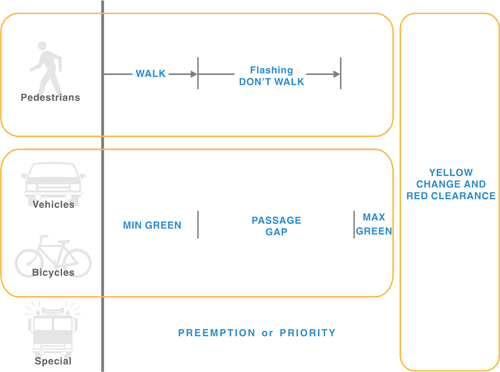
Parameters related to these intervals and discussed in this section include minimum green, maximum green, yellow-change, red clearance, pedestrian walk, and pedestrian flashing don’t walk (FDW). Figure 5-1 depicts the relationship between these parameters and the user group associated with each interval that may time during a phase. These intervals time concurrently during a phase. Although shown here, signal preemption and priority are addressed in Chapter 9. Additional timing parameters related to actuated control (e.g., passage time) may also influence the duration of an interval and are discussed in Section 5.4.
Figure 5-1 Users and the actuated signal timing parameters that determine phase length 5-5
5.3.1 Vehicular Green Interval
The vehicular green interval is the time dedicated to serving vehicular traffic with a green indication. This interval is defined primarily by the minimum and maximum green parameters in the case of an isolated intersection. At an actuated controller, other parameters (e.g., passage time) also determine the length of this interval. Those parameters are discussed in Section 5.4. It is also possible that the duration of the vehicle green interval may be defined by the length of the associated pedestrian intervals.
Minimum Green
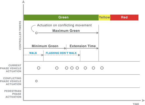
The minimum green parameter represents the least amount of time that a green signal indication will be displayed for a movement. Minimum green is used to allow drivers to react to the start of the green interval and meet driver expectancy. Its duration may also be based on considerations of queue length or pedestrian timing in the absence of pedestrian call buttons and/or indications. A minimum green that is too long may result in wasted time at the intersection; one that is too short may violate driver expectation or (in some cases) pedestrian safety. The minimum green interval is shown in Figure 5-2, as it relates to other intervals and signal control parameters. Calls placed on the active phase during the minimum green have no bearing on the duration of the green interval as the interval will time at least as long as the minimum green timer.
Lin (5) conducted extensive simulation analysis of fully-actuated controlled intersections to determine the effect of minimum green intervals on delay. Through these simulations, he found that delay was minimal when the minimum green interval was less than 4 seconds. Delay for the intersection under the scenarios studied tended to increase slightly as the minimum green interval increased from 4 to 8 seconds.
Figure 5-2 Settings that define the duration of a vehicle phase
The intent of the minimum green interval is to ensure that each green interval is displayed for a length of time that will satisfy driver expectancy. When stop-line detection is not provided, variable initial, as described in Section 5.4, should be used to allow vehicles queued between the stop line and the nearest detector at the start of green to clear the intersection. In cases where separate pedestrian signal displays are not provided, the minimum green interval will also need to be long enough to accommodate pedestrians who desire to cross in a direction parallel to the traffic movement receiving the green indication. These considerations and the conditions in which each applies are shown in Table 5-2.
| Phase | Stop Line Detection? | Pedestrian Button? | Considered in Establishing Minimum Green? | ||
|---|---|---|---|---|---|
| Driver Expectancy | Pedestrian Crossing Time | Queue Clearance | |||
| Through | Yes | Yes | Yes | No | No |
| No | Yes | Yes | No | ||
| No | Yes | Yes | No | Yes, if actuated | |
| No | Yes | Yes | Yes, if actuated | ||
| Left-Turn | Yes | Not applicable | Yes | Not applicable | No |
To illustrate the use of Table 5-2, consider a through movement with stop-line detection and a pedestrian push button. As indicated in the table, the minimum green interval should be based solely on driver expectancy. However, if a pedestrian call button is not provided (and pedestrians are expected to cross the road at this intersection), the minimum green interval should be based on driver expectancy and pedestrian crossing time.
Minimum Green to Satisfy Driver Expectancy
The duration of minimum green needed to satisfy driver expectancy varies among practitioners. Some practitioners rationalize the need for 15 seconds or more of minimum green at some intersections; other practitioners use as little as 2 seconds minimum green. If a minimum green parameter is set too low and violates driver expectancy, there is a risk of increased rear-end crashes. The values listed in Table 5-3 are typical for the specified combination of phase and facility type.
| Phase Type | Facility Type | Minimum Green Needed to Satisfy Driver Expectancy (Ge), s |
|---|---|---|
| Through | Major Arterial (speed limit exceeds 40 mph) | 10 to 15 |
| Major Arterial (speed limit is 40 mph or less) | 7 to 15 | |
| Minor Arterial | 4 to 10 | |
| Collector, Local, Driveway | 2 to 10 | |
| Left Turn | Any | 2 to 5 |
Minimum Green for Pedestrian Crossing Time
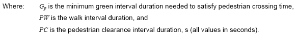
The minimum green duration must satisfy pedestrian crossing needs for through phases that are not associated with a pedestrian push button but have a pedestrian demand. Under these conditions, the minimum green needed to satisfy pedestrian considerations can be computed using Equation 5-1. Methodology for computing walk and pedestrian clearance interval durations are provided in Section 5.3.3.
Equation 5-1
Minimum Green for Queue Clearance
The duration of minimum green can also be influenced by detector location and controller operation. This subsection addresses the situation where a phase has one or more advance detectors and no stop-line detection. If this detection design is present, and the added initial parameter (as discussed later) is not used, then a minimum green interval is needed to clear the vehicles queued between the stop line and the advance detector. The duration of this interval is specified in Table 5-4.
| Distance Between Stop Line and Nearest Upstream Detector, ft | Minimum Green Needed to Satisfy Queue Clearance1, 2 (Gq), s |
|---|---|
| 0 to 25 | 5 |
| 26 to 50 | 7 |
| 51 to 75 | 9 |
| 76 to 100 | 11 |
| 101 to 125 | 13 |
| 126 to 150 | 15 |
- Minimum green values listed apply only to phases that have one or more advance detectors, no stop line detection, and the added initial parameter is not used.
- Minimum green needed to satisfy queue clearance, Gq = 3 + 2n (in seconds), where n = number of vehicles between stop line and nearest upstream detector in one lane. And, n = Dd / 25, where Dd = distance between the stop line and the downstream edge of the nearest upstream detector (in feet) and 25 is the average vehicle length (in feet), which could vary by area.
If a phase has one or more advance detectors, no stop-line detection, and the added initial parameter is used, then the minimum initial interval should equal the minimum green needed to satisfy driver expectancy. Timing of minimum greens using the added initial parameter is discussed in Section 5.4.
Maximum Green
The maximum green parameter represents the maximum amount of time that a green signal indication can be displayed in the presence of conflicting demand. Maximum green is used to limit the delay to any other movement at the intersection and to keep the cycle length to a maximum amount. It also guards against long green times due to continuous demand or broken detectors. Ideally, the maximum green will not be reached because the detection system will find a gap to end the phase, but if there are continuous calls for service and a call on one or more conflicting phases, the maximum green parameter will eventually terminate the phase. A maximum green that is too long may result in wasted time at the intersection. If its value is too short, then the phase capacity may be inadequate for the traffic demand, and some vehicles will remain unserved at the end of the green interval.
Most modern controllers provide two or more maximum green parameters that can be invoked by a time-of-day plan or external input (i.e., Maximum Green 2). As shown in Figure 5-2, the maximum green extension timer begins timing upon the presence of a conflicting call. If there is demand on the phase that is currently timing and no conflicting calls, the maximum green timer will be reset until an opposing call occurs.
It should be noted that the normal failure mode of a detector is to place a continuous call for service. In this case, a failed detector on a phase will cause that phase’s maximum green to time every cycle.
Many modern controllers also provide a feature that allows the maximum green time to be increased to a defined threshold after maxing out a phase a certain number of consecutive times (or alternatively to select among two or three maximum green values). The maximum green time may then be automatically decreased back to the original value after the phase has gapped out a certain number of times. The exact methods and user settable parameters for this feature vary by manufacturer.
The maximum green value should exceed the green duration needed to serve the average queue and, thereby, allow the phase to accommodate cycle-to-cycle peaks in demand. Frequent phase termination by gap out (as opposed to max out) during low-to-moderate volumes and by occasional max out during peak periods is commonly used as an indication of a properly timed maximum green duration. Example values are listed in Table 5-5.
| Phase | Facility Type | Maximum Green, s |
|---|---|---|
| Through | Major Arterial (speed limit exceeds 40 mph) | 50 to 70 |
| Major Arterial (speed limit is 40 mph or less) | 40 to 60 | |
| Minor Arterial | 30 to 50 | |
| Collector, Local, Driveway | 20 to 40 | |
| Left Turn | Any | 15 to 30 |
- Range is based on the assumption that advance detection is provided for indecision zone protection. If this type of detection is not provided, then the typical maximum green range is 40 to 60 s.
Two methods are commonly used to establish the maximum green setting. Both estimate the green duration needed for average volume conditions and inflate this value to accommodate cycle-to-cycle peaks. Both of these methods assume that advance detection for indecision zone protection is not provided. If advance detection is provided for indecision zone protection, the maximum green setting obtained from either method may need to be increased slightly to allow the controller to find a “safe” time to terminate the phase by gap out.
One method used by some agencies is to establish the maximum green setting based on an 85th to 95th percentile probability of queue clearance (6). The procedure requires knowledge of the cycle length, or an estimate of its average value for actuated operation. If the cycle length is known, then the maximum green setting for a signal phase can be obtained from Table 5-6.
| Phase Volume per Lane, veh/hr/ln | Cycle Length, s | |||||||
|---|---|---|---|---|---|---|---|---|
| 50 | 60 | 70 | 80 | 90 | 100 | 110 | 120 | |
| Maximum Green (Gmax)1, s | ||||||||
| 100 | 15 | 15 | 15 | 15 | 15 | 15 | 15 | 15 |
| 200 | 15 | 15 | 15 | 15 | 16 | 18 | 19 | 21 |
| 300 | 15 | 16 | 19 | 21 | 24 | 26 | 29 | 31 |
| 400 | 18 | 21 | 24 | 28 | 31 | 34 | 38 | 41 |
| 500 | 22 | 26 | 30 | 34 | 39 | 43 | 47 | 51 |
| 600 | 26 | 31 | 36 | 41 | 46 | 51 | 56 | 61 |
| 700 | 30 | 36 | 42 | 48 | 54 | 59 | 65 | 71 |
| 800 | 34 | 41 | 48 | 54 | 61 | 68 | 74 | 81 |
The values listed are based on the equation shown in the table footnote. Due to the approximate nature of this equation, the actual percentage probability of queue clearance varies between the 85th and 95th percentiles for the values listed.
A second method for establishing the maximum green setting is based on the equivalent optimal pre-timed timing plan (7). This method requires the development of a pre-timed signal timing plan based on delay minimization. The minimum-delay green interval durations are multiplied by a factor ranging from 1.25 to 1.50 to obtain an estimate of the maximum green setting (8).
The maximum green time used for a particular phase is calculated differently for low and high levels of saturation. During periods of low volume, when the green phase times rarely reach their maximum values, the maximum green time can be set fairly high (up to 1.7 times the calculated average time for the phase). This accommodates most fluctuations in vehicle arrival rates. During conditions at or near saturation, it is important to set the maximum green times as if they were fixed time, equitably allocating the green based on the critical lane volumes as described in Chapter 3.
To this end, application of the maximum green times show significant disparity in the techniques reported for determination of maximum phase time, which ultimately may result in a wide variation of cycle lengths at intersections. In many cases, maximum green times are set at one value throughout the day and don’t reflect the needs of the intersection during various times of day. In some cases, these maximum green time values result in cycle lengths that are too long for efficient operations.
5.3.2 Vehicular Change and Clearance Intervals
The intent of the vehicle phase change and clearance intervals is to provide a safe transition between two conflicting phases. It consists of a yellow change interval and, optionally, a red clearance interval. The intent of the yellow change interval is to warn drivers of the impending change in right-of-way assignment. The red clearance interval is used when there is some benefit to providing additional time before conflicting movements receive a green indication.
Yellow Change
The duration of the yellow change interval is typically based upon driver perception-reaction time, plus the distance needed to safely stop or to travel safely through the intersection.
A state’s Uniform Vehicle Code directly affects yellow change interval timing, as it determines whether a permissive or restrictive yellow law is in place.
- Permissive Yellow Law: A driver can enter the intersection during the entire yellow interval and be in the intersection during the red indication as long as the vehicle entered the intersection during the yellow interval. Under permissive yellow law, an all-red clearance interval must exist as a timing parameter to ensure safe right-of-way transfer at an intersection. This rule is consistent with paragraph 11-202 of the Uniform Vehicle Code (9).
- Restrictive Yellow Law: There are two variations of this law (10). In one variation, a vehicle may not enter an intersection when the indication is yellow unless the vehicle can clear the intersection by the end of yellow. This implies that the yellow duration should be sufficiently long as to allow drivers the time needed to clear the intersection if they determine that it is not possible to safely stop. In the other variation, a vehicle may not enter an intersection unless it is impossible or unsafe to stop. With restrictive yellow law, the presence of an all-red interval is optional and good engineering judgment should be applied.
Due to the varying interpretations of the yellow change use, it is encouraged that traffic engineers refer to the local and regional statutes for guidance in determining the purpose of the yellow change time.
Red Clearance
The red clearance interval, referred to in some publications as an all-red interval, is an interval at the end of the yellow change interval during which the phase has a red-signal display before the display of green for the following phase. The purpose of this interval is to allow time for vehicles that entered the intersection during the yellow-change interval to clear the intersection prior to the next phase. Note that the use of the “all-red” nomenclature is generally incorrect, as the red clearance interval only applies to a single phase, not to all phases.
The use of a red clearance interval is optional, and there is no consensus on its application or duration. Recent research has indicated that the use of a red clearance interval showed some benefit to the reduction of red-light-running violations. In these studies, there was a significant reduction in right-angle crashes after implementing a red clearance interval. Other research suggests that this reduction may only be temporary. A comprehensive study of long-term effects for the Minnesota Department of Transportation ()11, indicated short-term reductions in crash rates were achieved (approximately one year after the implementation), but long-term reductions were not observed, which implies that there may not be safety benefits associated with increased red clearance intervals.
A disadvantage of using the red clearance interval is that there is a reduction in available green time for other phases. At intersections where the timing for minor movements is restricted (e.g., to split times under coordinated operation (see Chapter 6)), the extra time for a red clearance interval comes from the remaining phases at the intersection. In cases where major movements are already at or near saturation, the reduction in capacity associated with providing red clearance intervals for safety reasons should be accounted for in an operational analysis.
The MUTCD provides guidance on the application and duration of the yellow change and red clearance intervals. It recommends that the interval durations shall be predetermined based on individual intersection conditions, such as approach speed and intersection width. The MUTCD advises that the yellow change interval should last approximately 3 to 6 seconds, with the longer intervals being used on higher-speed approaches. It also advises that the red clearance interval should not exceed 6 seconds. A recent survey conducted by The Urban Transportation Monitor indicated that practitioners who used a standard red clearance interval used a range from 0.5 to 2.0 seconds.
Kell and Fullerton (12) offer the following equation for computing the phase change period (yellow change plus red clearance intervals):
Equation 5-2
![CP = [ t + (1.47v / 2(a + 32.2g)) ] + [ (W + L sub V) / 1.47v ]](images/eq5_2.png)
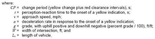
Equation 5-2 is based on driver reaction time, approach speed, approach grade, and intersection width and consists of two terms. The first term (yellow change) represents the time required for a vehicle to travel one safe stopping distance, including driver perception-reaction time. This permits a driver to either stop at the intersection if the distance to the intersection is greater than one safe stopping distance or safely enter the intersection (and clear the intersection under the restrictive yellow law) if the distance to the intersection is less than one safe stopping distance. The second term (red clearance) represents the time needed for a vehicle to traverse the intersection ([W + Lv]/v). Although values will vary by driver population and local conditions, the values of t = 1.0 s, a = 10 ft/s2, and Lv = 20 ft are often cited for use in Equation 5-3 (,,131415). These values of perception-reaction time and deceleration rate are different from those cited in highway geometric design policy documents because they are based on driver response to the yellow indication, which is an expected condition. They are not based on the longer reaction time necessary for an unexpected (or surprise) condition.
When applying Equation 5-2 to through movement phases, the speed used is generally either the 85th-percentile speed or the posted regulatory speed limit, depending on agency policy (16). When applying Equation 5-2 to left-turn movement phases, the speed used should reflect that of the drivers that intend to turn. This speed can equal that of the adjacent through movement but it can also be slower as left-turn drivers inherently slow to a comfortable turning speed. Regardless, if the left-turn phase terminates concurrently with the adjacent through phase, it will have the same total change and clearance interval durations as the through phase because the phases are interlocked by the ring-barrier operation.
The width of the intersection is often defined by local policy or state law. For instance, in Arizona intersection width is defined by state law as the distance between prolongations of the curb lines. Where intersection width is not defined by local policies, engineering judgment should be used when measuring the width of the intersection, W. One approach is to measure from the near-side stop line to the far edge of the last conflicting traffic lane along the subject movement travel path. If crosswalks are present at the intersection, some agencies have policies to measure from the near-side stop line to the far side of the pedestrian crosswalk on the far side of the intersection (for through-movement phases) or to the far side of the pedestrian crosswalk across the leg of the intersection which the left-turn is entering. This is a jurisdiction-wide issue that must be carefully applied.
| Approach Speed, mph |
“t + v/2a” Terms, s (YELLOW) |
Width of Intersection, ft | ||||
|---|---|---|---|---|---|---|
| 30 | 50 | 70 | 90 | 110 | ||
| “(W+Lv)/v” Term, s (ALL-RED) | ||||||
| 25 | 3.0a | 1.4 | 1.9 | 2.5 | 3.0 | 3.5 |
| 30 | 3.2 | 1.1 | 1.6 | 2.0 | 2.5 | 3.0 |
| 35 | 3.6 | 1.0 | 1.4 | 1.8 | 2.1 | 2.5 |
| 40 | 3.9 | 0.9 | 1.2 | 1.5 | 1.9 | 2.2 |
| 45 | 4.3 | 0.8 | 1.1 | 1.4 | 1.7 | 2.0 |
| 50 | 4.7 | 0.7 | 1.0 | 1.2 | 1.5 | 1.8 |
| 55 | 5.0 | 0.6 | 0.9 | 1.1 | 1.4 | 1.6 |
| 60 | 5.4 | 0.6 | 0.8 | 1.0 | 1.2 | 1.5 |
a The 2003 MUTCD recommends a minimum duration of 3 seconds for the yellow change interval.
The values for the yellow change interval in Table 5-7 are based on negligible approach grade. They should be increased by 0.1 second for every 1 percent of downgrade. Similarly, they should be decreased by 0.1 second for every 1 percent of upgrade. To illustrate, consider an approach with a 30 mph approach speed, 70-foot intersection width, and 4-percent downgrade. The estimated change period is 5.6 seconds (= 3.2 + (0.1 x 4 + 2.0)).
States that follow the “restrictive yellow” rule may equate the yellow change interval to the value obtained from Equation 5-2 (i.e., the sum of both terms). If a red-clearance interval is needed, its value may be set at 0.5 to 2 seconds, as determined by engineering judgment.
States that follow the “permissive yellow” rule will typically set the yellow change interval equal to the value obtained from the first term of Equation 5-2 (i.e., column 2 of Table 5-7), but not less than 3.0 seconds. This duration will allow drivers that do not have the necessary distance to stop the time needed to reach the intersection before the red indication is presented. If a red clearance interval is needed, its value is typically based on the second term of Equation 5-2 (i.e., columns 3 through 7 of Table 5-7). Some agencies reduce the value of the second term by 1.0 second in recognition of the perception-reaction time of drivers in the next conflicting phase to be served (17).
5.3.3 Pedestrian Timing Intervals
The pedestrian phase consists of three intervals: walk; pedestrian clearance, commonly referred to as flashing don’t walk (FDW); and solid don’t walk. The walk interval typically begins at the start of the green interval and is used to allow pedestrians to react to the change to walk at the start of the phase and move into the crosswalk. This interval corresponds to the WALKING PERSON indication on the pedestrian signal (18). The pedestrian clearance interval follows the walk interval and informs pedestrians the phase is ending. During this interval, the UPRAISED HAND indication flashes on the pedestrian signal. The solid don’t walk interval follows the pedestrian clearance interval and is indicated by a solid UPRAISED HAND indication. This interval is an indication to the pedestrian that they should have cleared the crosswalk and opposing vehicle movements could begin. The solid don’t walk time is not a programmable parameter in the controller. The duration of the solid don’t walk interval is simply the length of the cycle minus the walk and pedestrian clearance intervals.
Although the illustration in Figure 5-2 does not include a pedestrian phase activation, it does show that the pedestrian timers (walk and FDW) would time concurrently with the vehicle intervals if there was a pedestrian activation. In the case of Figure 5-2, the pedestrian intervals are shown as requiring less time than allowed by the maximum green timer. In this case, if there was continuing vehicle demand, the pedestrian indication would show a solid don’t walk until the vehicle phase terminated due to lack of demand or the maximum green timer expired. However, if the pedestrian intervals required more time than permitted by the maximum green timer, the vehicle phase would continue to time until the pedestrian flashing don’t walk interval finished timing.
Walk
The walk interval should provide pedestrians adequate time to perceive the WALK indication and depart the curb before the pedestrian clearance interval begins. It should be long enough to allow a pedestrian that has pushed the pedestrian push button to enter the crosswalk. In many cases, the pedestrian phase will be set to rest in the walk interval to maximize the walk display during a vehicle green. Some controllers have a mechanism to specify that the walk interval begins before, or even after, the onset of the green interval. The walk interval may be extended in some controllers during coordination. A pedestrian recall mode, as discussed in a later section, can be used to eliminate the need for a pedestrian to push buttons and ensures that the pedestrian phase is presented each cycle.
The length of the walk interval is usually established in local agency policy. The MUTCD () 19indicates that the minimum walk duration should be at least 7 seconds, but indicates that a duration as low as 4 seconds may be used if pedestrian volumes are low or pedestrian behavior does not justify the need for 7 seconds. Consideration should be given to walk durations longer than 7 seconds in school zones and areas with large numbers of elderly pedestrians. In cases where the pedestrian push button is a considerable distance from the curb, additional WALK time is desirable. Table 5-8 summarizes the recommended walk interval durations based on the guidance provided in the MUTCD and the Traffic Control Devices Handbook ()20. At intersections where older pedestrians are present, the MUTCD recommends that the WALK time allows for a pedestrian to reach the middle of the street at a 3.0 feet per second walking speed.
| Conditions | Walk Interval Duration (PW), s |
|---|---|
| High pedestrian volume areas (e.g., school, central business district, sports venues, etc.) | 10 to 15 |
| Typical pedestrian volume and longer cycle length | 7 to 10 |
| Typical pedestrian volume and shorter cycle length | 7 |
| Negligible pedestrian volume | 4 |
| Conditions where older pedestrians are present | Distance to center of road divided by 3.0 feet per second |
WALK times that allow pedestrians to cross to a wide median before the FLASHING DON’T WALK may reduce the potential for pedestrians stopping within the median.
Pedestrian Clearance
The pedestrian clearance interval follows the walk interval. When the pedestrian clearance interval begins, pedestrians should either complete their crossing if already in the intersection or refrain from entering the intersection until the next pedestrian walk interval is displayed. The MUTCD currently stipulates that the pedestrian clearance interval must be calculated assuming the distance from the curb to the far side of the opposing travel way, or to a median of sufficient width for pedestrians to wait. Note that previous editions of the MUTCD only required the clearance time to be as long as needed for the pedestrian to reach the center of the farthest traveled lane.
Pedestrian clearance time is computed as the crossing distance divided by the walking speed. The speed of pedestrians is a critical assumption in determining this parameter. The MUTCD recommends a walking speed value of 4.0 feet per second (ft/s). The Americans with Disabilities Act (ADA) Accessibility Guidelines for Buildings and Facilities recommended use of 3.0 ft/s. Recent work completed by LaPlante and Kaeser has suggested that a speed of 3.5 ft/s be used to calculate the pedestrian clearance (FDW and Yellow) duration for curb to curb clearance and 3.0 ft/s be used for the total pedestrian time (WALK, FDW, and Yellow) duration for top of ramp to far curb clearance. The Pedestrian Facilities User Guide (21) recommends a maximum walking speed of 3.5 ft/s. This guide also suggests that a slower walking speed should be used in areas where there is a heavy concentration of elderly persons or children. A survey by Tarnoff and Ordonez (22) suggests a range of 3.0 to 3.5 ft/s is typically used by agencies to compute crossing time for these special-needs pedestrians. Pedestrian clearance time for typical pedestrian crossing distances can be obtained from Table 5-9.
| Pedestrian Crossing Distance, ft | Walking Speed, ft/s | ||
|---|---|---|---|
| 3.0 | 3.5 | 4.0 | |
| Pedestrian Clearance Time (PCT), s | |||
| 40 | 13 | 11 | 10 |
| 60 | 20 | 17 | 15 |
| 80 | 27 | 23 | 20 |
| 100 | 33 | 29 | 25 |
- Clearance times computed as PCT = Dc / vp, where Dc = pedestrian crossing distance (in feet) and vp = pedestrian walking speed (in feet per second).
In general, agencies use one of two methods to determine the setting for the pedestrian clearance parameter. Some agencies require that the pedestrian clearance time conclude with the onset of the yellow change interval. This approach provides additional time (equal to the change period) for pedestrian clearance—time that is sometimes of benefit to pedestrians who walk slower than average. The pedestrian clearance interval duration for this practice is computed using Equation 5-3.
Equation 5-3
Other agencies allow a portion of the pedestrian clearance time to occur during the change period (i.e., yellow change or yellow change plus red clearance intervals). This practice minimizes the impact of pedestrian service on phase duration and allows it to be more responsive to vehicular demand. This pedestrian clearance interval duration is computed using Equation 5-4.
Equation 5-4
The practice of exclusing the change and clearance intervals may place pedestrians at risk if a concurrent permissive left turn movement is receiving a yellow and the vehicles from that movement are expected to clear the intersection during the yellow interval. Some agencies using flashing yellow applications choose to omit the permissive left turn portion of a protected-permissive left-turn movement during a pedestrian call.
The pedestrian clearance time that transpires during the green interval coincides with a flashing “DON’T WALK” indication. At the onset of the yellow interval, a steady “DON’T WALK” indication is presented. It is noted that some agencies display the flashing “DON’T WALK” until the end of the change period. However, the MUTCD (Sections 4E.07 and 4E.10) states that if countdown pedestrian signals are used, the pedestrian clearance interval must finish timing before the onset of the yellow clearance interval.
5.4 ACTUATED TIMING PARAMETERS
Research has shown that the best form of isolated operation occurs when fully-actuated controllers are used. Actuated controllers operate most effectively when timed in a manner that permits them to respond rapidly to fluctuations in vehicle demand (23). This section describes several of the more commonly used settings and parameters that influence phase function or duration in an actuated controller, including phase recall, passage time, simultaneous gap, and dual entry. In addition, this section discusses the volume-density technique.
5.4.1 Phase Recalls
Recall causes the controller to place a call for a specified phase each time the controller is servicing a conflicting phase, regardless of the presence of any detector-actuated calls for the phase. There are four types of recalls: minimum recall (also known as vehicle recall), maximum recall, pedestrian recall, and soft recall. These are specified as phase option parameters in NTCIP Document 1202 (24).
Minimum Recall (Vehicle Recall)
The minimum recall parameter causes the controller to place a call for vehicle service on the phase. The phase is timed at least for its minimum green regardless of whether there is demand on the movement. The call is cleared upon start of green for the affected phase and placed upon start of the yellow change interval. This may be used where detection has failed.
Minimum recall is the most frequently used recall mode. It is frequently used for the major-road through-movement phases (commonly designated as phases 2 and 6) at semi-actuated non-coordinated intersections. This use ensures that the controller will always return to the major-road through phases regardless of demand on the major-road through phases, thus providing a green indication as early as possible in the cycle.
Maximum Recall
The maximum recall parameter causes the controller to place a continuous call for vehicle service on the phase. It results in the presentation of the green indication for its maximum duration every cycle as defined by the maximum green parameter for the phase. When the maximum recall parameter is selected for a phase, the maximum green timer begins timing at the beginning of the phase’s green interval, regardless of the presence of a conflicting call or lack thereof.
There are at least three common applications of maximum recall:
- Fixed-time operation is desired: Each phase is set for maximum recall. The maximum green setting used for this application should be equal to the green interval durations associated with an optimal fixed time plan.
- Vehicle detection is not present or is out of service: Maximum recall for a phase without detection ensures that the phase serves the associated movement. However, maximum recall can result in inefficient operation during light volume conditions (e.g., during night times and weekends) and should be used only when necessary. In some of these situations, a lower maximum green or MAX 2 (50 to 75% of the typical MAX GREEN value) may be desirable.
- Gapping out is not desired: Maximum recall can be used to prevent a phase from gapping out. An example application of this is under coordinated operations where a left turn phase is lagging. By setting the lagging left turn phase to maximum recall, the phase will time for its maximum duration, allowing the adjacent coordinated phase to also time
for its intended maximum duration. This type of operation is typically only used on a time-of-day basis in conjunction with a particular coordinated plan (see Chapter 6).
Pedestrian Recall
The pedestrian recall parameter causes the controller to place a continuous call for pedestrian service on the phase, resulting in the controller timing its walk and flashing don’t walk operation. Coordination plans may invoke pedestrian calls using a rest in walk command, which dwells in the pedestrian walk interval, while awaiting the yield point.
There are at least two common applications of pedestrian recall:
- Pedestrian detection is not present or is out of service: Pedestrian recall for a phase without pedestrian detection ensures that the phase times pedestrian walk and clearance intervals each cycle.
- High pedestrian demand: Pedestrian recall is sometimes used to activate the Walk and Pedestrian clearance intervals for phases and time periods that are likely to have high pedestrian demand. This is a common application during periods of high pedestrian activity in downtown environments or at intersections near schools as students are arriving or leaving school for the day.
Soft Recall
The soft recall parameter causes the controller to place a call for vehicle service on the phase in the absence of a serviceable conflicting call. When the phase is displaying its green indication, the controller serves the phase only until the minimum green interval times out. The phase can be extended if actuations are received. This may be used during periods of low traffic when there is a desire to default to the major street.
The most typical application for soft recall is for the major-road through movement phases (usually phases 2 and 6) at non-coordinated intersections. The use of soft recall ensures that the major-road through phases will dwell in green when demand for the conflicting phases is absent.
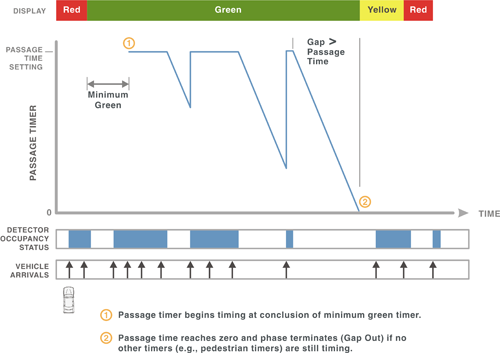
5.4.2 Passage Time
Passage time, sometimes called passage gap, vehicle extension, or unit extension, is used to extend the green interval based on the detector status once the phase is green. This parameter extends the Green Interval for each vehicle actuation up to the Maximum Green. It begins timing when the vehicle actuation is removed. This extension period is subject to termination by the Maximum Green timer or a Force Off.
Passage time is used to find a gap in traffic for which to terminate the phase, essentially it is the setting that results in a phase ending prior to its maximum green time during isolated operation. If the passage time is too short, the green may end prematurely, before the vehicular movement has been adequately served. If the passage interval is set too long, there will be delays to other movements caused by unnecessary extension of a phase (25,) resulting in delay to the other movements at the intersection. The appropriate passage time used for a particular signal phase depends on many considerations, including: type and number of detection zones per lane, location of each detection zone, detection zone length, detection call memory (i.e., locking or nonlocking), detection mode (i.e., pulse or presence), approach speed, and whether lane-by-lane or approach detection is used. Ideally, the detection design is established and the passage time determined to ensure that the “system” provides efficient queue service and safe phase termination for higher speed approaches. Detection design procedures that reflect these considerations are described in Chapter 4.
The passage timer starts to time from the instant the detector actuation is removed. A subsequent actuation will reset the passage timer. Thus, the mode of the detector, pulse or presence, is extremely important in setting the passage time. The pulse mode essentially measures headways between vehicles and the passage time would be set accordingly. The speed of the vehicles crossing the detectors and the size of the detectors is an important consideration in determining passage time when using presence mode. Longer passage times are often used with shorter detectors, greater distance between the detector and stop line, fewer lanes, and slower speeds.
When the passage timer reaches the passage time limit, and a call is waiting for service on a conflicting phase, the phase will terminate, as shown in Figure 5-3. When this occurs, it is commonly termed as a “gap out”. In the figure, vehicle calls extend the green time until the gap in detector occupancy is greater than the passage time. In this example, presence detection is assumed.
Research by Tarnoff suggests that the vehicle extension interval is one of the most important actuated controller settings, but the variety of techniques for determining proper settings suggest that there is either a lack of knowledge on the availability of this information or disagreement with the conclusions presented (26).
Figure 5-3 Application of passage time
The objective when determining the passage time value is to make it large enough to ensure that all vehicles in a moving queue are served but to not make it so large that it extends the green for randomly arriving traffic. This objective is broadened on high-speed approaches to ensure the passage time is not so large that the phase cannot be safely terminated.
Many professionals believe that keeping one lane of traffic (in a left turn or a minor street) moving in deference to a major street with multiple lanes results in inefficient operation. Research has shown that measuring flow rates across lane groups and comparing them with the potential demand at an approach may provide improved decision making within the signal control logic.
The guidelines provided in this section are based on the assumption that non-locking memory is used and that one source of detection is provided (per lane) for the subject signal phase. This source of detection could consist of one long detector loop at the stop line, a series of 6-foot loops that are closely spaced and operate together as one long zone of detection near the stop line, or a single 6-foot loop located at a known distance upstream of the stop line (and no detection at the stop line). As discussed in Chapter 4, passage time is a design parameter for detection designs that include multiple detectors for the purpose of providing safe phase termination (i.e., indecision zone protection). The passage-time value for this application is inherently linked to the detection design and should not be changed from its design value.
Passage time defines the maximum time separation that can occur between vehicle calls without gapping out the phase. When only one traffic lane is served during the phase, this maximum time separation equals the maximum allowable headway (MAH) between vehicles. Although the maximum time separation does not equal the maximum allowable headway when several lanes are being served, the term "MAH" is still used and it is understood that the "headway" represents the time interval between calls (and not necessarily the time between vehicles in the same lane).
Figure 5-4 illustrates the relationship between passage time, gap, and maximum allowable headway for a single-lane approach with one detector. This relationship can be used to derive the following equation for computing passage time for presence mode detection. Gap as shown in this figure is the amount of time that the detection zone is unoccupied.
Equation 5-5
![PT = MAH - [(L sub v + L sub d) / 1.47v sub a]](images/eq5_3.png)
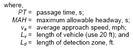
Figure 5-4 Relationship between passage time, gap, and maximum allowable headway
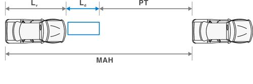
If Equation 5-5 is used with pulse-mode detection, then the length of vehicle Lv and the length of detector Ld equal 0.0 ft, and the passage time is equal to the MAH. The duration of the passage time setting should be based on three goals (27):
- Ensure queue clearance. The passage time should not be so small that the resulting MAH causes the phase to have frequent premature gap-outs (i.e., a gap-out that occurs before the queue is fully served). A premature gap-out will leave a portion of the stopped queue unserved and, thereby, lead to increased delays and possible queue spillback. If the queue is extraordinarily long and cannot be accommodated without creating a cycle length that is longer than desirable, this goal may not apply.
- Satisfy driver expectancy. The passage time should not be so large that the green is extended unnecessarily after the queue has cleared. Waiting drivers in conflicting phases will become anxious and may come to disrespect the signal indication.
- Reduce max-out frequency. The passage time should not be so large that the resulting MAH causes the phase to have frequent max-outs. A long MAH would allow even light traffic volumes to extend the green to max-out. Waiting drivers in higher-volume conflicting phases may be unfairly delayed.
Research by Tarnoff and Parsonson (28) indicates that there is a range of passage times within efficient intersection operations. This range extends from about 1 to 4 seconds for presence mode detection, with lower values being more appropriate under higher volume conditions. Values outside this range tend to increase delay. These passage times correspond to MAH values in the range of 2.0 to 4.5 seconds, depending on detection zone length and location.
Based on the previous discussion, the following MAH values are recommended for use with Equation 5-3 to determine passage time:
- Gap reduction not used: MAH = 3.0 s
- Gap reduction used: MAH = 4.0 s
The recommended MAH values may be increased by 0.1 s if the approach is on a steep upgrade and by 1.0 seconds if there is a large percentage of heavy vehicles.
The passage time computed from the recommended MAH values for a range of speeds and detection zone lengths is provided in Table 5-10 for presence mode detection. It is critical that the relationship of passage time to vehicle speed, detector length, and detector location be considered.
| Maximum Allowable Headway, s | Detection Zone Length, ft | 85th Percentile Approach Speed, mph1 | ||||
|---|---|---|---|---|---|---|
| 25 | 30 | 35 | 40 | 45 | ||
| Passage Time (PT), s | ||||||
| 3.0 | 6 | 2.2 | 2.3 | 2.4 | 2.5 | 2.6 |
| 15 | 1.9 | 2.1 | 2.2 | 2.3 | 2.4 | |
| 25 | 1.6 | 1.8 | 2.0 | 2.1 | 2.2 | |
| 35 | 1.3 | 1.6 | 1.8 | 1.9 | 2.1 | |
| 45 | 1.0 | 1.3 | 1.6 | 1.7 | 1.9 | |
| 55 | 0.7 | 1.1 | 1.3 | 1.6 | 1.7 | |
| 65 | 0.4 | 0.8 | 1.1 | 1.4 | 1.5 | |
| 75 | 0.1 | 0.6 | 0.9 | 1.2 | 1.4 | |
| 4.0 | 6 | 3.2 | 3.3 | 3.4 | 3.5 | 3.6 |
| 15 | 2.9 | 3.1 | 3.2 | 3.3 | 3.4 | |
| 25 | 2.6 | 2.8 | 3.0 | 3.1 | 3.2 | |
| 35 | 2.3 | 2.6 | 2.8 | 2.9 | 3.1 | |
| 45 | 2.0 | 2.3 | 2.6 | 2.7 | 2.9 | |
| 55 | 1.7 | 2.1 | 2.3 | 2.6 | 2.7 | |
| 65 | 1.4 | 1.8 | 2.1 | 2.4 | 2.5 | |
| 75 | 1.1 | 1.6 | 1.9 | 2.2 | 2.4 | |
- Average approach speed is computed as 88 percent of the 85th percentile approach speed.
5.4.3 Simultaneous Gap
Simultaneous gap defines how a barrier is crossed when a conflicting call is present. If enabled, it requires all phases that are timing concurrently to simultaneously reach a point of being committed to terminate (by gap-out, max-out, or force-off) before they can be allowed to jointly terminate. If disabled, each of the concurrent phases can reach a point of being committed to terminate separately and remain in that state while waiting for all concurrent phases to achieve this status. Simultaneous gap out should be enabled when advance detection is used to provide safe phase termination.
5.4.4 Dual Entry
The dual (double) entry parameter is used to call vehicle phases that can time concurrently even if only one of the phases is receiving an active call. For example, if dual entry is active for Phases 2 and 6 and Phase 1 receives a call but no call is placed on Phase 6, Phase 6 would still be displayed along with Phase 1. The most common use of dual entry is to activate the parameter for compatible through movements. If the dual entry parameter is not selected, a vehicle call on a phase will only result in the timing of that phase in the absence of a call on a compatible phase.
5.5 VOLUME-DENSITY FEATURES
Volume-density features can be categorized by two main features: gap reduction and variable initial. These features permit the user to provide variable alternatives to the otherwise fixed parameters of passage time (gap reduction) and minimum green (variable initial). Gap reduction provides a way to reduce the allowable gap over time, essentially becoming more aggressive in looking for an opportunity to end the phase. Variable initial provides an opportunity to utilize cycle by cycle traffic demand to vary the minimum time provided for a phase. These features increase the efficiency of the cycle with the fluctuations in demand, which can result in lower delay for users at the intersection.
5.5.1 Gap Reduction
The gap reduction feature reduces the passage time to a smaller value while the phase is green. Initially, the gap sought between actuations is the passage time value. Then, after a specified time (Time Before Reduction), the passage timer is reduced to a minimum gap using a gradual reduction over a specified time (Time To Reduce). This functionality is achieved by programming the following controller parameters: time before reduction, time to reduce, and minimum gap. Their relationship is shown in Figure 5-5.
Figure 5-5 Use of volume-density to change the extension time
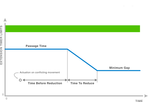
The time-before-reduction parameter establishes the time that is allowed to elapse after the arrival of a conflicting call and before the extension timer limit is reduced. This period begins when the phase is green and there is a serviceable call on a conflicting phase. Once the time-before-reduction period expires, the extension timer limit is reduced in a linear manner until the time-to-reduce period expires. Thereafter, the extension timer limit is set equal to the minimum-gap parameter. Like the Passage Time, this parameter extends the green interval by up to the Minimum Gap time for each vehicle actuation up to the Maximum Green. It begins timing when the vehicle actuation is removed. This extension period is subject to termination by the Maximum Green or a Force Off.
The gap-reduction feature may be desirable when the phase volume is high and it is difficult to differentiate between the end of the initial queue and of the subsequent arrival of randomly formed platoons. This feature allows the user to specify a higher passage time at the beginning of a phase and then incrementally reduce the passage time as a phase gets longer and the delay to conflicting movements increases.
With gap reduction, a MAH of 2.0 seconds is recommended for use with Equation 5-3 to determine the minimum gap. This MAH may be increased by 0.1 second if the approach is on a steep upgrade, and by 1.0 second if there is a large percentage of heavy vehicles.
If Equation 5-3 is used with pulse-mode detection, then the length of vehicle Lv and the length of detector Ld equal 0.0 ft, and the minimum gap is equal to the MAH.
The minimum gap is computed and shown in Table 5-11 using the recommended MAH values for a range of speeds and detection zone lengths provided for presence mode detection.
| Maximum Allowable Headway, s | Detection Zone Length, ft | 85th Percentile Approach Speed, mph1 | ||||
|---|---|---|---|---|---|---|
| 25 | 30 | 35 | 40 | 45 | ||
| Minimum Gap, s | ||||||
| 2.0 | 6 | 1.2 | 1.3 | 1.4 | 1.5 | 1.6 |
| 15 | 0.9 | 1.1 | 1.2 | 1.3 | 1.4 | |
| 25 | 0.6 | 0.8 | 1.0 | 1.1 | 1.2 | |
| 35 | 0.3 | 0.6 | 0.8 | 0.9 | 1.1 | |
| 45 | 0.0 | 0.3 | 0.6 | 0.7 | 0.9 | |
| 55 | 0.0 | 0.1 | 0.3 | 0.6 | 0.7 | |
| 65 | 0.0 | 0.0 | 0.1 | 0.4 | 0.5 | |
| 75 | 0.0 | 0.0 | 0.0 | 0.2 | 0.4 | |
- Average approach speed is computed as 88 percent of the 85th percentile approach speed.
A number of different policies may be employed in determining the value of time-before-reduction. An example policy is to make the time-before-reduction setting equal to the minimum green interval and the time-to-reduce setting equal to half the difference between the maximum and minimum green intervals (29). This guidance is illustrated in Table 5-12.
| Minimum Green Interval, s | Time Before Reduction1, s | Maximum Green, s | ||||||||||
|---|---|---|---|---|---|---|---|---|---|---|---|---|
| 20 | 25 | 30 | 35 | 40 | 45 | 50 | 55 | 60 | 65 | 75 | ||
| Time To Reduce, s | ||||||||||||
| 5 | 10 | 8 | 10 | 13 | 15 | 18 | 20 | 23 | 25 | 28 | 30 | 33 |
| 10 | 10 | 5 | 8 | 10 | 13 | 15 | 18 | 20 | 23 | 25 | 28 | 30 |
| 15 | 15 | N/A | 5 | 8 | 10 | 13 | 15 | 18 | 20 | 23 | 25 | 28 |
| 20 | 20 | N/A | N/A | 5 | 8 | 10 | 13 | 15 | 18 | 20 | 23 | 25 |
- Time before reduction should always be 10 s or more in length.
5.5.2 Variable Initial
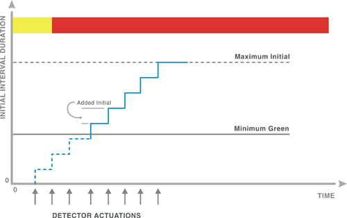
Variable initial is used in some cases to ensure that all vehicles queued between the stop line and the nearest upstream detector are served. Variable initial uses detector activity to determine a minimum green. Vehicles arriving on red that are not able to reach the upstream detector due to a standing queue will be detected and will extend the green by an amount sufficient to allow them to be served using the passage time. This feature is applicable when there are one or more advance detectors, no stop-line detection, and wide fluctuations in traffic volumes between peak and off-peak hours. Variable initial timing is achieved by programming the following controller parameters: minimum green, added initial, and maximum initial. Their relationship is shown in Figure 5-6.
Added Initial – This interval times concurrently with the minimum green interval, and is increased by each vehicle actuation received during the associated phase yellow and red intervals. The initial green time portion is the greater of the minimum green or added initial intervals. The Added Initial cannot exceed the Maximum Initial (Figure 5-6).
Maximum Initial – This is the maximum period of time for which the Added Initial can extend the initial green period. The Maximum Initial can not be less than the Minimum Green (Figure 5-6).
Figure 5-6 Use of Added Initial to modify minimum green
As with other volume-density parameters, there are varying policies that may be employed in determining the values of maximum-initial and added-initial. Generally, the maximum initial setting should be determined using the calculation for minimum green for queue clearance shown in Section 5.3.1.
A common policy for selecting the added-initial parameter is to set this value at approximately 2.0 seconds per actuation if the phase serves only one traffic lane, 1.5 seconds per actuation if it serves two traffic lanes, and 1.2 seconds per actuation if it serves three or more lanes. Slightly larger values can be used if the approach has a significant upgrade or a significant number of heavy trucks. Bicycle traffic may also warrant higher values depending on the intersection width. Some agencies have developed more specific calculations for determining the added initial parameter. For example, the Los Angeles Department of Transportation uses Equation 5-4 to calculate the added initial setting.
Equation 5-6
5.6 DETECTION CONFIGURATION AND PARAMETERS
Traffic signal controllers have several settings that can be used to modify the vehicle actuations. Traditionally, this functionality was available only in the detection unit that served as an interface between the vehicle detector and the signal controller. Its implementation in the controller unit has streamlined the signal timing process and can duplicate functionality that may be in the detection unit.
The parameters discussed in this section include: delay, extend, call, and queue. The latter two parameters are actually elements of the detector options in NTCIP Document 1202 (30).
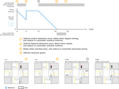
5.6.1 Delay
A delay parameter can be used to postpone a vehicle actuation for a detector input on a phase. By using a delay timer, an actuation is not made available until the delay timer expires and the actuation channel input is still active (i.e., the detection zone is still occupied). Once an actuation is made available to the controller, it is continued for as long as the channel input is active. Application of the delay timer is illustrated in Figure 5-7.
Figure 5-7 Application of delay timer
Common applications of a delay parameter on detection include the following:
- Delay is sometimes used with stop-line, presence mode detection for turn movements from exclusive lanes. For right-turn-lane detection, delay should be considered when the capacity for right-turn-on-red (RTOR) exceeds the right-turn volume or a conflicting movement is on recall. If RTOR capacity is limited, then delay may only serve to degrade intersection efficiency by further delaying right-turn vehicles. The delay setting should range from 8 to 12 seconds, with the larger values used for higher crossroad volumes (31).
- If the left-turn movement is protected-permissive and the opposing through phase is on minimum (or soft) recall, then delay should be considered for the detection in the left turn lane. The delay setting should range from 3 to 7 seconds, with the larger values used for higher opposing volumes (32). In this case, a minimum recall should also be placed on the adjacent through phase to ensure that a lack of demand on the adjacent through phase does not result in the left-turn movement receiving neither a permissive nor a protected left-turn indication.
- Delay may also be used to prevent an erroneous call from being registered in the controller if vehicles tend to traverse over another phase’s detector zone. For example, left-turning vehicles often cut across the perpendicular left-turn lane at the end of their turning movement. A detector delay coupled with non-locking memory would prevent a call from being placed for the unoccupied detector.
5.6.2 Extend
The extend parameter is used to increase the duration of the actuation for a detector or phase. The extend timer begins the instant the actuation channel input is inactive. Thus, an actuation that is one second in duration at the channel input can be extended to three seconds, if the extend parameter is set to two seconds. This process is illustrated in Figure 5-8.
Figure 5-8 Application of extend timer
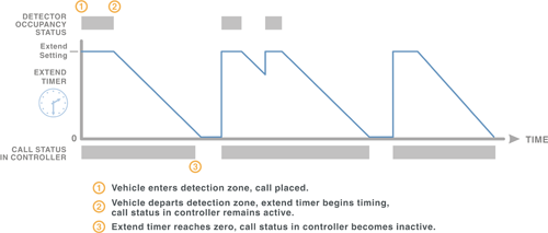
Extend is typically used with detection designs that combine multiple advance detectors and stop-line detection for safe phase termination of high-speed intersection approaches. Extend is used with specific upstream detectors to supplement the passage-time parameter, to ensure that these detectors can extend the green interval by an amount of time equal to the sum of the passage time and call extension. The magnitude of the extension interval is dependent on the passage time, approach speed, and the distance between the subject detector and the next downstream detector. Typical values range from 0.1 to 2.0 seconds.
The objective when used at high-speed approaches is to extend the green interval to ensure that a vehicle approaching the intersection has just enough time to reach the next downstream detector and place a new call for green extension. The procedure for identifying when call extension is needed and computing the amount of the extension time is specific to the detection design. Refer to the Manual of Traffic Detector Design by Bonneson and McCoy (33) for additional guidance on this application.
5.6.3 Carryover
Carryover is a term commonly used for the Extend setting in controller manuals. It is another way to describe the time provided for a vehicle to traverse from one detector to the next.
5.6.4 Call
The call parameter is used to allow actuations to be passed to the controller for the assigned phase when it is not timing a green interval. Actuations received during the green interval are ignored. The call parameter is sometimes used with detection designs that include one or more advance detectors and stop-line detection. With this design, the call-only parameter is used with the stop-line detectors to ignore the actuations these detectors receive during the green interval. The advance detectors are used to ensure safe and efficient service during the green interval. When an appropriate detection design is combined with this parameter, intersection efficiency can be improved by eliminating unnecessary green extension by the stop-line detection.
5.6.5 Queue
A detector can be configured as a queue service detector to effectively extend the green interval until the queue is served, at which time it is deactivated until the start of the next conflicting phase. This functionality is offered as a parameter in most modern controllers. However, if it is not available as a parameter, equivalent functionality can be acquired by using the features of many modern detector amplifiers.
This functionality is sometimes used with detection designs that include one or more advance detectors and stop-line detection. With this design, the queue service functionality is used to deactivate the stop line detection during the green interval, but after the queue has cleared. The advance detectors are then used to ensure safe phase termination. When combined with an appropriate detection design, this functionality can improve intersection efficiency by eliminating unnecessary green extension by the stop-line detection.
5.7 GUIDELINES FOR TIME-BASE CONTROLS
Most controllers provide a means to externally apply signal timing parameters by time of day; typically these include maximum green, phase omit, and minimum recall on a time-of-day basis. Depending on the manufacturer, time-of-day selection of pedestrian omit, maximum recall, pedestrian recall, detector switching, overlap omit, additional maximums, alternate walk intervals, and other parameters may also be available. The approach specified by NTCIP 1202 for activating phase and ring controls invokes a timing pattern that can be selected on a time-of-day basis (34). In NTCIP protocol, a timing pattern consists of a cycle length, offset, set of minimum green and maximum green values, force off (determined by splits in some cases), and phase sequence. It also includes specification of phase parameters for minimum or maximum vehicle recall, pedestrian recall, or phase omit. This will be further described in Chapter 6.
There are a number of controls that can be used to modify controller operation on a time-of-day basis. A remote entry to one of these controls will invoke the corresponding parameter. The most common time-based controls are maximum green 2 (Max 2), phase omit, and minimum recall. The method of activating these controls varies from manufacturer to manufacturer.
There are two typical uses of phase omit. One use is when a left-turn phase is only needed during the peak traffic period. A second use is where a left-turn movement is prohibited during the peak period. In this situation, the associated left-turn phase is omitted during the turn prohibition period.
Minimum recall is used primarily on the major-road phase(s) of a fully-actuated, non-coordinated intersection. If the volume on the minor road is low only during certain times of the day, minimum recall for the major-road phases could be activated during these time periods.
5.8 REFERENCES
- National Transportation Communications for ITS Protocol: Object Definitions for Actuated Traffic Signal Controller (ASC) Units – 1202 v01.07. National Electrical Manufacturers Association, Rosslyn, Virginia, January 2005
- NEMA Standards Publications TS 2-2003 v2.06: Traffic Controller Assemblies with Controller Requirements. National Electrical Manufacturers Association, Rosslyn, Virginia, 2003
- Orcutt, F.L. The Traffic Signal Book. Prentice Hall, Englewood Cliffs, New Jersey, 1993
- Skabardonis, A., R. Bertini, B.Gallagher, “Development and Application of Control Strategies for Signalized Intersections in Coordinated Systems” Transportation Research Record No. 1634. Transportation Research Board, National Research Council, Washington, D.C., 1998, pp. 110-117
- Lin, F.B. “Optimal Timing Settings and Detector Lengths of Presence Mode Full-Actuated Control.” Transportation Research Record No. 1010. Transportation Research Board, National Research Council, Washington, D.C., 1985, pp. 37-45
- Parsonson, P.S. NCHRP Synthesis 172: Signal Timing Improvement Practices. Transportation Research Board, National Research Council, Washington, D.C., 1992
- Kell, J. H., and Fullerton, I. J., Manual of Traffic Signal Design. 2nd Edition. Institute of Transportation Engineers, Washington, D.C., 1998
- Skabardonis, Alexander, Progression Through a Series of Intersections with Traffic Actuated Controllers, Volume 2 User’s Guide, FHWA RD-89-133, Washington, D.C., October 1998
- Uniform Vehicle Code - Millennium Edition. National Committee on Uniform Traffic Laws and Ordinances. Alexandria, Virginia, 2000
- Parsonson, P.S. 1992
- Souleyrette, R. R., O’Brien, M. M., McDonald, T., Preston, H., and Storm, R., “Effectiveness of All-Red Clearance Interval on Intersection Crashes”, Center for Transportation Research and Education, Iowa State University, Minnesota Department of Transportation, MN/RC-2004-26, http://www.lrrb.org/PDF/200426.pdf, May 2004
- Kell, J. H., and Fullerton, I. J. 1998
- Ibid
- Traffic Engineering Handbook. 5th Edition. J.L. Pline editor. Institute of Transportation Engineers, Washington, D.C., 1999
- Traffic Control Devices Handbook. J.L. Pline editor. Institute of Transportation Engineers, Washington, D.C., 2001
- Tarnoff, P.J. "Traffic Signal Clearance Intervals." ITE Journal. Institute of Transportation Engineers, Washington, D.C. April 2004, pp. 20-24
- Traffic Control Devices Handbook. 2001
- Manual on Uniform Traffic Control Devices. U.S. Department of Transportation, Washington, D.C., December 2003
- Ibid
- Traffic Control Devices Handbook. J.L. Pline editor. Institute of Transportation Engineers, Washington, D.C., 2001
- Zegeer, C.V., C. Seiderman, P. Lagerway, M. Cynecki, M. Ronkin, and R. Schneider. Pedestrian Facilities User’s Guide - Providing Safety and Mobility. Report No. FHWA-RD-01-102. U.S. Department of Transportation, Federal Highway Administration, Washington, D.C., 2002
- Tarnoff, P.J., and J. Ordonez. Signal Timing Practices: State of the Practice. Institute of Transportation Engineers, Washington, D.C., March 2004
- Ibid
- National Transportation Communications for ITS Protocol: January 2005
- Henry, RD, “Signal Timing on a Shoestring”, Federal Highway Administration, FHWA-HOP-07-006, March 2005.
- Tarnoff, P. and Ordonez, 2004.
- Bonneson, J. A., and P.T. McCoy. Manual of Traffic Detector Design, 2nd Edition. Institute of Transportation Engineers, Washington DC, May 2005
- Tarnoff, P.J., and P.S. Parsonson. NCHRP Report 233: Selecting Traffic Signal Control at Individual Intersections. Transportation Research Board, National Research Council, Washington, D.C., 1981
- UDOT Procedural Update - Timing of Traffic Signals. Traffic Operations Center, Utah Department of Transportation, Ogden, Utah, April 15, 2004
- National Transportation Communications for ITS Protocol: January 2005
- Bonneson, J.A., and M. Abbas. Intersection Video Detection Manual. Report FHWA/TX-03/4285-2. Texas Department of Transportation, Austin, Texas, September 2002
- Bonneson, J. A., and P.T. McCoy. 2005
- Ibid
- National Transportation Communications for ITS Protocol: January 2005 5-30