Road Weather Information System
Environmental Sensor Station
Siting Guidelines
April 2005
4.0 Recommended Siting Criteria
The following siting criteria can be used to help select an optimal observation site. Criteria are subdivided into siting the observation tower and placing sensors on or adjacent to the tower. These recommendations strike a balance between established atmospheric sensor siting criteria such as those documented in World Meteorological Organization (WMO)12, and NWS13, standards and road-specific weather information requirements. The exact suite of sensors installed at a particular site will depend on the road weather information requirements. Mounting the sensors on a tower will require careful planning so the sensors do not interfere with each other. The availability of rights-of-way to install the site should be verified. Surroundings should be assessed for potential obstructions to selected sensors and potential sensor contaminants (e.g., water and dust sources) should be identified. Complete documentation of the tower and sensor location and exposure should be maintained for each location in a metadata file and made available at a central location (e.g., a website). Variations in sensor or tower siting may be unavoidable due to many circumstances, such as:
- Limited road rights-of-way
- Access requirements for power and/or communications
- Ease in access for maintenance
- Geography (e. g., terrain, water bodies) and neighboring structures
- Aesthetic considerations imposed by individuals and agencies
- Security concerns
- City, county, or state codes.
4.1 Observation Tower
Considerations for the structure and siting of an ESS tower are as follows:
- The tower should be sturdy (e.g., open matrix type), using instrument booms to reduce contamination of sensor data by turbulence and wind flow around the tower structure. For water level and road flooding applications, standpipes (i.e., vertical pipes ranging from 3 to 12 inches (7.6 to 30.4 centimeters) in diameter and up to 10 feet (3 meters) tall such as shown in Figure 5) are typically used. Masts can be placed above the top of the standpipe to mount wind, air temperature/dewpoint, or other weather sensors. In this situation, the weather sensors may not be consistent with the siting guidelines below; however, the sensors should be installed high enough above the top of the standpipe to eliminate the environmental effect caused by the standpipe.
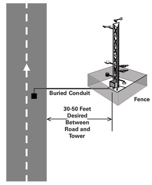
- At this time, there are no studies that determine the minimum distance the tower should be placed from the roadway to avoid the effects of traffic on the accuracy of the sensors (e.g., heat, wind, splash) or how close it must be to adequately represent the environment over the roadway. Towers are most frequently installed within a range of 30-50 feet (9-15 meters) from the edge of the paved surface. Figure 6 depicts a desired tower location relative to the roadway.
|
Figure 6. Desired Tower Location Relative to Roadway |
- The tower base should be attached to a concrete pad to provide a sturdy platform. The size of the pad should take into consideration the soil conditions, frost activity, and wind loading. If the tower is within the clear zone, a barrier or guard rail should be used.
- The tower base should be at the same elevation as the surface of the road, if possible.
- The tower height should depend on the planned sensors. If a wind sensor is planned, the tower should be tall enough to install it at a height of 33 feet (10 meters).
- Towers should be sited on relatively flat terrain. If possible, avoid steep slopes within 300 feet (approximately 90 meters) that could impact wind measurements. Sites near steep road cuts, swampy areas, and bedrock (a detriment to cable trenching) should be avoided.
- If possible, towers should be placed upwind of the roadway based on the predominant wind direction for the season of most interest. The nearest NWS Forecast Office or State Climatologist can provide predominant wind directions. Additionally, road maintenance personnel can often provide anecdotal information that will help determine the predominant wind direction along a given road segment.
- The surrounding terrain coverage out to at least 50 feet (15 meters) should be low vegetation or native soil.
- Avoid standing water. Many ESSs are installed on the opposite side of a depression adjacent to the road. This depression is a natural collection point for rain and/or water draining off the road. Given the choice of two potential sites, both of which would satisfy other siting requirements, the ESS should be installed in the one less likely to be affected by ponding water.
- A fence should cordon off the tower from its surroundings if the threat of vandalism is present. If possible, the distance between the fence and the tower should be at least 15 feet (5 meters). This distance is recommended to minimize the effect of the fence on the sensors readings especially when weeds and/or debris on the fence act as a horizontal obstruction. Limited space in the right-of-way may require the distance between the fence and tower to be reduced. The positioning of the fence and its gate should not restrict access to the equipment or the tower. Careful planning is necessary to assure that fold-over towers with their attached instrumentation may be lowered with sufficient room for a technician to work on the sensors. The fence should not obstruct any sensors on the tower.
- Anti-climb panels can be installed to restrict persons from climbing up the open lattice of towers.
- Ease of maintenance tasks should be considered in the siting, such as the use of folding towers and the availability of maintenance vehicle pull offs. In some situations, sensor heights may need to be adjusted to accommodate maintenance activities.
- Insufficient space in the right-of-way outside the clear zone may preclude installation of a tower. If requirements for road weather information preclude selecting another site, DOTs may find other options for installing some atmospheric sensors. For example, anemometers can be installed on light standards or utility poles. The anemometer should be placed on top of the pole to minimize disturbances in the air flow. If no pole is available, an anemometer can be mounted on a sign bridge. The mounting site should be selected to minimize disturbances from any signs or from the sign bridge. Consider mounting the anemometer on an instrument boom in the predominant upwind direction. Additionally, long-wave radiation sensors can be installed on a sign bridge to collect data over the road surface for input into road temperature models. Temperature and moisture sensors should not be mounted on top of light standards or utility poles or on sign bridges, as their resulting height would preclude obtaining representative data.
- The positioning of the tower and the height of the sensors on the tower should be included in the metadata file available for the data customers.
- Refer to wind sensor criteria in Section 4.2 for obstruction restrictions.
4.2 Sensor Location
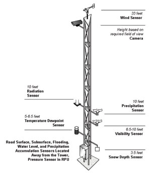
Figure 7 shows the typical locations of sensors mounted on a tower as discussed in the following text. Refer to Section 3.2 for local sensor siting guidelines that differ from the recommended guidelines below. Sensor heights may need to be elevated in areas that receive heavy snow.
|
Figure 7. Typical Location of Tower-Based Sensors |
- Air Temperature/Dewpoint Sensor. This probe should be located in a radiation shield in a well ventilated area and mounted 5-6.5 feet (1.5-2 meters) above ground level. The sensor should be on a boom extended from the tower at least 3 feet (1 meter) towards the predominant wind direction. In areas where road frost is a recurring consideration, a second dewpoint sensor mounted lower to the pavement height may help identify the potential for frost formation.
- Wind Speed and Direction Sensor (anemometer). This sensor should be positioned 33 feet (10 meters) above ground level. Obstructions to the wind flow should be avoided. A general rule is that the sensor should be positioned at a distance of 10 times the height of the nearest large obstruction, e.g., if the obstruction is 20 feet (6.1 meters) tall, the wind sensor should be positioned 200 feet (61 meters) away from the obstruction. The wind direction sensor should be set on true north (rather than magnetic north).
- Optically-based Precipitation Sensors (Rate, Type, and Amount). These sensors should be installed at a height of 10 feet (3 meters) to avoid contamination from debris. Install these sensors away from traffic, as they are susceptible to vibration. Optical sensors should be installed to avoid the sun and stray light sources from entering the receiver element.
- Visibility Sensors. These sensors should be installed at a height of 6.5-10 feet (2-3 meters). This height is lower than the NWS and FAA Automated Surface Observing System (ASOS),14 minimum height of 10 feet (3 meters), but above the 1.5-meter height the WMO recommends for non-aviation applications.15 This height was selected to better represent a driver-level observation. Optical sensors should be installed to avoid the sun and stray light sources from entering the receiver element.
- Snow Depth Sensors. These sensors are based on ultrasonic or infrared emissions. They should be installed perpendicular to the surface at a height of approximately 3.5 feet (1 meter). The sensor should have an unobstructed view of the target and should be mounted so as to avoid vibrations.
- Shortwave Solar Radiation Sensor. These sensors should be installed at a height of at least 10 feet (3 meters). These sensors should be placed high enough to avoid radiation from reflective surfaces or shading from obstructions.
- Longwave Radiation Sensors. These sensors measure incoming and outgoing radiation in the infrared portion of the energy spectrum. The balance of these two radiation processes is extremely important in determining the potential for nighttime cooling. They should be installed at a height of 10 feet (3 meters) to avoid debris contamination. These sensors should be installed on the tower with a clear field of view (i.e., free from obstructions). To measure longwave radiation directly above the road surface, consider placing the sensor on a sign bridge.
- Cameras, both visible and infrared. Cameras should be installed where they are able to obtain a clear line-of-sight and not interfere with the operation of any other sensors. If the requirement is for visibility measurements, the camera should be installed as close as possible to the driver's level of view. Continuously imaging cameras may require additional power and communications bandwidth.
- Pavement Temperature and Pavement Condition Sensors. The initial consideration in the deployment of pavement sensors is in satisfying the agency needs to monitor or predict pavement conditions. Pavement sensors can be installed where pavement conditions are representative of general road conditions (i.e., part of a regional ESS) and/or where specific road weather problems are likely to occur. The installation of a pavement sensor meant to be representative of a larger road segment includes slightly different considerations than the installation meant to detect or monitor a specific road weather condition or concern. For example, in most situations pavement sensors should be sited in unshaded areas to represent the surrounding roadway segment under maximum cooling conditions. However, in road segments where shaded pavement is prevalent, such as hilly or mountainous areas, DOTs may consider siting additional sensors in the shaded areas to provide a better indication of local, cold weather road conditions.
Transportation operations and maintenance practices and concerns define where the pavement sensors should be located. On multilane roadways, consideration should be given to installing several sensors in different lanes. If only one sensor is to be installed, the typical lane selection is the travel lane, the rightmost lane in a multilane roadway. If sensors will not be placed in each lane of a multilane road in an urban environment, consideration should be given to siting the pavement sensors in the travel lane of morning outbound traffic. Icy roads are most often a concern during the predawn and morning hours. Placing the pavement sensor in morning outbound traffic will reduce the influence of heavy vehicle traffic on pavement observations.
In order to optimize the investment in an ESS location, sites are often selected that include installation of at least one sensor in an open road environment and one sensor in a bridge deck. Consider installing the pavement sensors on the second bridge span from the abutment where the flow of air affects the deck temperature and in the approach roadway far enough back from the abutment so that the sensor measures the pavement temperature away from the bridge's effects.
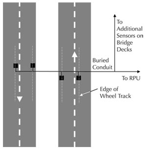
Once a lane is selected, where to install the pavement sensor within the lane becomes the next consideration. In general, pavement sensors should be installed near the edge of the inside wheel track. A typical pavement sensor siting is presented in Figure 8. The sensor location should be adjusted to avoid wheel track depressions, as a depressed wheel track will be susceptible to water ponding that could contaminate sensor readings. For similar reasons, care should be taken in locating the sensor to avoid drainage onto the sensor from the shoulder or median. Pavement temperatures can be as much as 2°F (1°C) higher in lane centers. Accordingly, placing pavement sensors in the center of a lane is not recommended.16 The sensor should be implanted flush with the pavement. On grooved pavement, the sensors should be implanted flush with the top of the grooves.
|
Figure 8. Typical Pavement Sensor Siting |
- Subsurface Temperature and Moisture Sensors. These sensors should be installed at a depth of 12 or 18 inches (30.5 or 45.5 centimeters), depending on the manufacturer-provided guidelines. Installation at multiple depths should be considered for backup or more detailed analysis. The installation location should be representative of sub grades in the area to include the presence or absence of water, similar soil types, and pockets of foreign materials. For ease of replacement, avoid burying subsurface sensors directly below pavement sensors.
- Precipitation Accumulation Sensor. The tipping bucket and weighing rain gauge are the most common ESS precipitation accumulation sensors. The tipping bucket often underreports rainfall totals in heavy precipitation. A weighing gauge can measure both solid and liquid precipitation and is more sensitive to light precipitation events. Both sensors require a heating device in freezing climates. DOTs may want to consider new technologies such as the hot-plate rain gauge which determines precipitation amounts by measuring the power needed to evaporate precipitation falling on a sensor plate. Additionally, commercially available all-weather precipitation accumulation gauges are being deployed as part of NWS and FAA automated surface observing systems. Exposure is the primary consideration for siting a precipitation sensor. Place the instrument in as open an area as possible and away from the roadway to prevent splashing. Consider the use of a wind shield to increase accuracy of the measurement (not required for a hot-plate rain gauge). Avoid areas of possible blowing or drifting snow. If mounted on a tower, the sensor should have an unobstructed field of view above it. Because the tower itself may influence precipitation measurements, it may be desirable to physically separate the precipitation sensor from the primary tower and remotely transmit the data to the tower RPU or boost the signal for a longer cable distance.
- Barometric Pressure Sensor (barometer). These sensors can be installed at any height but should be encased in a protective shelter to avoid exposure to the elements and any wide temperature changes.
- Water Level Sensors. These sensors typically consist of an ultrasonic, infrared, or float water-level sensor installed in a standpipe. For water-level sensors, the standpipes should be located in a low turbulent (i.e., steady flowing) portion of a flowing creek or river adjacent to a flood-prone road segment or bridge. If installed on or adjacent to a bridge, the sensors should be sited on the downstream side to minimize damage from floating debris. To detect road flooding, the standpipes should be installed adjacent to the low point of a roadway segment prone to flooding. In this situation, the standpipes are normally located in a parking area away from traffic or behind a guardrail.
12 World Meteorological Organization: Guide to Meteorological Instruments and Methods of Observation, Sixth Edition, WMO-No. 8, 1996.

13 National Weather Service. Operations and Services, Surface Observing Program (Land), Instrument Requirements and Standards for the NWS Surface Observing Programs. Policy Directive 10-1302, October 17, 2003.
14 National Weather Service. Automated Surface Observing System (ASOS) User's Guide. March 1998.
15 World Meteorological Organization: Guide to Meteorological Instruments and Methods of Observation, Sixth Edition, WMO-No. 8, 1996.
16 Boselly, S.E., J.E. Thornes, and C. Ulburg. Road Weather Information Systems Volume 1, Research Report. Strategic Highway Research Program Publication - SHRP-H-350, National Research Council, Washington, D.C., 1993.
|